EP2182592A2 - Connecteur à fiches - Google Patents
Connecteur à fiches Download PDFInfo
- Publication number
- EP2182592A2 EP2182592A2 EP09011114A EP09011114A EP2182592A2 EP 2182592 A2 EP2182592 A2 EP 2182592A2 EP 09011114 A EP09011114 A EP 09011114A EP 09011114 A EP09011114 A EP 09011114A EP 2182592 A2 EP2182592 A2 EP 2182592A2
- Authority
- EP
- European Patent Office
- Prior art keywords
- coding
- housing
- contact carrier
- connector according
- contact
- Prior art date
- Legal status (The legal status is an assumption and is not a legal conclusion. Google has not performed a legal analysis and makes no representation as to the accuracy of the status listed.)
- Granted
Links
Images

Classifications
-
- H—ELECTRICITY
- H01—ELECTRIC ELEMENTS
- H01R—ELECTRICALLY-CONDUCTIVE CONNECTIONS; STRUCTURAL ASSOCIATIONS OF A PLURALITY OF MUTUALLY-INSULATED ELECTRICAL CONNECTING ELEMENTS; COUPLING DEVICES; CURRENT COLLECTORS
- H01R13/00—Details of coupling devices of the kinds covered by groups H01R12/70 or H01R24/00 - H01R33/00
- H01R13/64—Means for preventing incorrect coupling
- H01R13/645—Means for preventing incorrect coupling by exchangeable elements on case or base
-
- H—ELECTRICITY
- H01—ELECTRIC ELEMENTS
- H01R—ELECTRICALLY-CONDUCTIVE CONNECTIONS; STRUCTURAL ASSOCIATIONS OF A PLURALITY OF MUTUALLY-INSULATED ELECTRICAL CONNECTING ELEMENTS; COUPLING DEVICES; CURRENT COLLECTORS
- H01R13/00—Details of coupling devices of the kinds covered by groups H01R12/70 or H01R24/00 - H01R33/00
- H01R13/46—Bases; Cases
- H01R13/502—Bases; Cases composed of different pieces
- H01R13/506—Bases; Cases composed of different pieces assembled by snap action of the parts
Definitions
- the invention relates to a connector having a first contact carrier, in which contacts are arranged, which enter into electrical contact with mating contacts of a second contact carrier in the arrangement of the contact carrier, wherein the first contact carrier comprises first coding means, which cooperate with second coding means of the second contact carrier and ensure a defined with respect to the connection of contacts and mating contacts arrangement of the contact carrier to each other.
- a generic connector is for example off DE 196 07 381 C2 known, where it is a connector according to Rast 5 standard. Also generic are connectors according to Rast 2.5 standard, which differ from the aforementioned connectors essentially only by the contact pitch.
- Connectors according to the Rast 5 or Rast 2.5 standard are connectors that have become particularly established in electrical household and kitchen appliances, heating controls and intrinsic wiring solutions of the automotive industry.
- Such connectors usually comprise a plug (second contact carrier) and a socket (first contact carrier), each in a generally multi-pole design.
- the term “plug” refers to the design of the "male” contact part, while the “socket” has “female” contact parts. Since most of the RAST connectors used on the market, the socket is that part which is attached to, for example, contact portions of a printed circuit board or a pin header, the socket is hereinafter referred to as a socket. Consequently, printed circuit boards, pin headers od. Like. Considered in the context of the invention as a plug or plug-in means.
- both parts have coding.
- the coding means selbiger are formed as PCB recesses or cuts in the contact area of the circuit board, which vary in their position, length and thickness.
- the housing forms with the cutouts corresponding coding walls.
- a colored coding is used at the plug-in.
- color markings are mounted, which can be found in the form of stickers, color bars or colored socket housings.
- the color marking can be designed as a complementary optical, quasi-redundant coding for unmatched fitting of socket and plug-in means or serve to mechanically coded identical sockets or plug-in means for further distinction in addition.
- the object of the invention is to simplify the production of connectors with in particular mechanical coding.
- a connector according to claim 1 which is characterized in particular by the fact that at least one contact carrier has a receptacle for an executed as a separate component coding.
- the essential advantage of the invention lies in the fact that standard contact carriers as well as separately the mechanical coding means can be manufactured so that the set-up times at the production plants are eliminated.
- a contact carrier with a corresponding coding is assembled from a standard contact carrier and separate coding means.
- the storage-stable holder can be achieved by the contact carrier has guides in which the coding engage in areas.
- the invention particularly relates to a connector whose first contact carrier is a housing of a socket. This is advantageously provided on the bottom side with locking means for holding the coding.
- the coding means for the housing is designed as a push-in coding wall, wherein in particular the socket housing for this pair has mutually associated grooves, engage in the sub-regions of the inserted into the socket housing coding wall for the purpose of position stabilization. It is advantageous if the coding wall in the insertion direction has latching means for arrangement in the socket housing.
- the coding wall can be used as a front wall with the socket housing open at the side.
- the coding wall has a set over a material weakening zone cut section, around which the coding wall can be shortened when used in a less deep compared to its length housing.
- the Kodierwand has at its standing with the housing of the socket in contact longitudinal sides shoulders, which enter into a snap connection with bushing side projections.
- the connector according to the invention is preferably a connector according to the catch 5 or Rast 2.5 standard.
- the above-described color coding can be carried out by means of appropriately colored coding means, in particular coding walls. This eliminates set-up times for the production of differently colored batches of contact carriers.
- the second contact carrier is a plug-in means, in particular a plug or a printed circuit board.
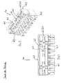
- Fig. 1 to 4 the housing of a socket of the prior art is shown and generally designated by the reference numeral 100.
- the housing 100 initially forms a plug-in opening 101 for receiving a plug-in means, not shown.
- the plug-in opening 101 is formed by two parallel, mutually spaced walls, each supporting a contact spring 102 (contact bearing walls 109).
- Optional end walls 107 connect the contact bearing walls 109.
- the plug-in means to be received by the plug-in opening 101 are usually a plug, a pin header or a plug connector PCB.
- a plurality of contact springs 102 are arranged in series next to each other. These go with not shown mating contacts of a plug means an electrical connection.
- the housing 100 itself is made of an insulating material, usually plastic.
- the contact bearing walls 109 form slot-like recesses 103 for the contact springs 102.
- the contact springs 102 are electrically isolated from one another by means of material webs 104 formed between the recesses 103.
- Cable entry openings 105 are used to connect electrical conductors to the contact springs 102.
- the contact springs 102 are rearward, i. on its side facing away from the plug-in opening insulation displacement contacts, by means of which the contact springs 102 are contacted on inserted into the cable insertion opening 105 conductor.
- socket has various coding. These are first coding walls 106, which are integrally formed integrally with the housing 100 within the insertion opening or as its end wall 107. These extend into the housing 100 at least to the bottom. Further coding means in the form of coding lugs 108 form the housing 100 on the outside.
- the basic idea of the invention relates to any mechanical coding means known from the prior art, for example the coding tabs 108. It is fundamentally advantageous if the coding means of the contact carriers, for example in the form of housing 100 or corresponding plug-in means, on or in these are stored interchangeably. Unless otherwise stated, however, the following description of the drawing refers to coding means in the form of coding walls 106 or their counterpart in the following description of exemplary embodiments according to the invention.
- the prior art according to Fig. 1 and 2 includes three coding walls 106, two of which form the end walls 107 of the housing 100.
- the embodiment of the prior art according to the 3 and 4 only via two Kodierprocess 106, namely designed as an end wall 107 and another mounted in the insertion opening Cod istswand 106.
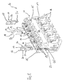
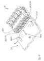
- a contact carrier in the sense of claim 4, the first contact carrier is designated here in the form of a housing of a socket with the reference numeral 10.
- the housing 10 of the socket comprises a made of insulating material, in particular plastic contact carrier 11, which serves a plug-in opening 12 for receiving a plug-in means, not shown, for example, a plug, a pin header or a printed circuit board section.
- the housing 10 according to the invention is also formed by two parallel contact bearing walls 26, which are spaced apart from each other in a gap-forming manner, and possibly by end walls 24.
- Vertical to the insertion opening 12 are cable insertion 13, analogous to the reference numeral 105 of the prior art, formed by the conductor, not shown, are introduced for electrical contacting with stored in the insertion opening 12 contact springs 14.
- cable holder 16 forms. By means of the cable holder 16, the cable ends can be arranged in parallel alignment with the insertion opening 12 on the contact carrier 11.
- the contact carrier 11 of the housing 10 forms externally circumferentially arranged, integrally cohesive Codieran arrangements 15. These correspond with recesses of a complementary plug-in housing and ensure a polarity-safe assembly of socket and plug-in housing.
- 17 coding which are pushed into the insertion opening 12.
- the contact bearing walls 26 within the insertion opening 12 initially in pairs against each other arranged guide grooves 19. These are oriented in the direction of insertion of the plug-in means, not shown, and receive corresponding wall sections 20 of the coding walls 18 for position stabilization.
- the Kodiermond 18 are provided in the insertion direction with locking means 21 which serve the anchorage in the bottom of the plug-in opening 22.
- the plug-in opening 12 is open at its narrow sides 23.
- Specially designed coding walls 18 form end walls 24, by means of which the narrow sides of the plug-in opening 12 can be closed for the purpose of plug coding.
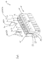
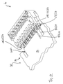
- Figure 6 shows an inventive housing 10 of a socket in a modified embodiment.
- the housing 10 of Fig. 6 has a slightly differently designed in detail contact carrier 11, wherein for the invention, only the differences described below are relevant.
- the depth of the insertion opening 12 in the in Fig. 6 embodiment shown is less than that in Fig. 5 ,
- the serving as the end walls 24 Codiercontent 18 have in contrast to those of Fig. 5 on its lying in the direction of insertion end no locking means. Instead, in the direction of the contact bearing walls 26 facing wall portions 20, the end walls 24 are provided with locking shoulders 27. These engage behind corresponding projections 28 in the guide grooves 19, but in Fig. 6 Not are shown. Due to the smaller depth of the insertion opening 12 and the coding walls 18 are designed to be shorter overall.
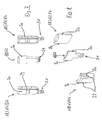
- Fig. 7 are the coding walls 18 according to Fig. 5 shown in Fig. 8 are the coding walls 17 according to Fig. 6 shown. Attention is particularly paid to the coding walls 18 formed as end walls 24 in FIG Fig. 7 to lay. These have material weakening zones 29, against which a shortening section 30 adjoins the insertion direction or at the end facing away from the latching means 21.
- end walls 24 can be used. These are then cut before, during or after assembly by cutting along the material weakening zone 29 around the section 30 (see Fig. 7 ). A similar embodiment of the in Fig. 8 illustrated end walls 24 is conceivable, which then connects a not shown here sectioning section on the insertion opposite end.
- FIGS. 9 and 10 is the housing 10 of the socket according to Fig. 6 shown in a sectional view.
- the section is in the direction of insertion of the end wall 24 in the end wall plane
- in Fig. 10 is the cut in the direction of insertion of the coding wall 18 in the plane.
- Fig. 9 Based on Fig. 9 can the latching of the end wall 24 in the housing 10 according to Fig. 6 clearly recognize.
- the guide grooves 19, in which the end wall 24 is inserted for the purpose of position stabilization, have projections 28 which are latched behind by the shoulders 27. This shows particularly clearly the detail enlargement IX of the Fig. 9 ,
- FIG Fig. 6 The latching behavior of the coding wall 18, which is described in FIG Fig. 6 is shown. Again, this is inserted for the purpose of position stabilization in opposite, introduced into the contact bearing walls 26 guide grooves 19, but the latching takes place through an opening in the bottom 22 of the insertion opening 12. In the region of the opening There are latching projections 31 which are engaged behind in the inserted state of the Kodierstegs 18 of the latch hook 32. This condition is clear in the enlargement X of the Fig. 10 shown.
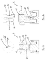
- a plug-in means 35 in the form of a printed circuit board 34 has a contact zone 36 facing the housing 10 with a multiplicity of conductor tracks, not shown, arranged side by side.
- the contact zone is interrupted by coding means 17 in the form of recesses 37.
- the arrangement is such that the housing 10 can be pushed in only one orientation to the contact zone 36 of the circuit board 34.
- the recesses 37 and coding walls 18 of housing 10 or circuit board 34 in the Fig. 11 and 12 each arranged in different positions.
- the housing 10 of the socket of Fig. 12 on the circuit board 34 of Fig. 11 or the housing of Fig. 11 on the circuit board 34 of Fig. 12 sit up.
- the coding of printed circuit board 34 and housing 10 is not only the polarity-reversible placement at the respective point of the circuit board but also prevents the placement of a housing with different coding.
- a contact carrier 11 has been shown in the form of a housing 10 of a socket, which can be produced as a standard component and the coding is done with coding 17 in the form of Kodierstroken 18 in retrospect.
- this has the decisive advantage that only a few standard components without makeready times can be continuously produced at the production facilities.
- Codiercontent 18 are integrally formed cohesively with the contact carrier 11.
Landscapes
- Details Of Connecting Devices For Male And Female Coupling (AREA)
- Coupling Device And Connection With Printed Circuit (AREA)
Priority Applications (1)
| Application Number | Priority Date | Filing Date | Title |
|---|---|---|---|
| SI200931150T SI2182592T1 (sl) | 2008-10-30 | 2009-08-31 | Vtični priključek |
Applications Claiming Priority (1)
| Application Number | Priority Date | Filing Date | Title |
|---|---|---|---|
| DE102008054015A DE102008054015B4 (de) | 2008-10-30 | 2008-10-30 | Steckverbinder |
Publications (3)
| Publication Number | Publication Date |
|---|---|
| EP2182592A2 true EP2182592A2 (fr) | 2010-05-05 |
| EP2182592A3 EP2182592A3 (fr) | 2012-06-13 |
| EP2182592B1 EP2182592B1 (fr) | 2014-12-24 |
Family
ID=41650189
Family Applications (1)
| Application Number | Title | Priority Date | Filing Date |
|---|---|---|---|
| EP09011114.7A Active EP2182592B1 (fr) | 2008-10-30 | 2009-08-31 | Connecteur à fiches |
Country Status (5)
| Country | Link |
|---|---|
| US (1) | US7997941B2 (fr) |
| EP (1) | EP2182592B1 (fr) |
| CN (1) | CN101728718A (fr) |
| DE (1) | DE102008054015B4 (fr) |
| SI (1) | SI2182592T1 (fr) |
Cited By (3)
| Publication number | Priority date | Publication date | Assignee | Title |
|---|---|---|---|---|
| DE102012107298A1 (de) * | 2012-08-09 | 2014-02-13 | Endress + Hauser Flowtec Ag | Aufsatzelement, Vorrichtung zur Anordnung in einem Messgerät und Messgerät |
| IT202100016016A1 (it) * | 2021-06-18 | 2022-12-18 | Marelli Automotive Lighting Italy S P A Con Socio Unico | Sistema di connessione elettrica per un faro o fanale di veicolo e dispositivo di illuminazione associato |
| EP4626156A1 (fr) * | 2024-03-26 | 2025-10-01 | Rockwell Automation Asia Pacific Business Center Pte. Ltd. | Composants de système de commande d'automatisation avec caractéristiques de codage électronique anti-erreur |
Families Citing this family (20)
| Publication number | Priority date | Publication date | Assignee | Title |
|---|---|---|---|---|
| CN102468578B (zh) * | 2010-11-16 | 2016-03-16 | 泰科电子(上海)有限公司 | 电连接器的壳体的防误插接装置的设计方法 |
| DE102011005544A1 (de) | 2011-03-15 | 2012-09-20 | Robert Bosch Gmbh | Verbesserte Mehrfach-Direktkontaktierung von elektrischen Bauteilen |
| DE202012002501U1 (de) | 2012-03-13 | 2013-06-17 | Lumberg Connect Gmbh | Steckkontakt zur Anordnung an einem Kontaktträger |
| DE102012004833A1 (de) | 2012-03-13 | 2013-09-19 | Lumberg Connect Gmbh | Steckkontakt zur Anordnung an einem Kontaktträger |
| DE102012103216A1 (de) * | 2012-04-13 | 2013-10-17 | Wago Verwaltungsgesellschaft Mbh | Steckverbinderset und Steckverbinder und Gegensteckverbinder hierzu |
| CN102723642A (zh) * | 2012-06-29 | 2012-10-10 | 华为技术有限公司 | 金手指连接器和防误插装置 |
| DE102013215787B4 (de) | 2013-08-09 | 2022-05-05 | Te Connectivity Germany Gmbh | Gehäuse für einen elektrischen Stecker, Bausatz, Stecker und Steckverbindung |
| DE102013108888A1 (de) * | 2013-08-16 | 2015-02-19 | Phoenix Contact Gmbh & Co. Kg | Kodierung für Grundleisten mit einer Mehrzahl an Kammern |
| DE102013110548B4 (de) * | 2013-09-24 | 2025-02-06 | Phoenix Contact E-Mobility Gmbh | Steckverbinderteil mit einer Widerstandkodierung |
| DE102014107948B3 (de) * | 2014-06-05 | 2015-07-30 | Wago Verwaltungsgesellschaft Mbh | Steckverbinderanordnung und Kodierelement hierzu sowie Verfahren zur Kodierung einer Steckverbinderanordnung |
| DE202015005042U1 (de) * | 2015-07-14 | 2015-09-09 | Rosenberger Hochfrequenztechnik Gmbh & Co. Kg | Steckverbindungsanordnung mit Kodierung |
| DE102016118870A1 (de) | 2016-10-05 | 2018-04-05 | Lumberg Connect Gmbh | Steckverbinder mit entfernbaren Kodierstiften |
| DE202016105525U1 (de) | 2016-10-05 | 2018-01-08 | Lumberg Connect Gmbh | Steckverbinder mit entfernbaren Kodierstiften |
| DE102018101667B3 (de) * | 2018-01-25 | 2019-04-11 | Lumberg Connect Gmbh | Steckverbinder mit Sekundärsicherung |
| DE102019111164A1 (de) * | 2019-04-30 | 2020-11-05 | Wago Verwaltungsgesellschaft Mbh | Steckverbinder einer elektrischen Steckverbindung sowie Set aus Steckverbinder und Funktionselement |
| JP7653769B2 (ja) * | 2019-04-30 | 2025-03-31 | ヴァーゴ・フェアヴァルトゥングスゲゼルシャフト・エムベーハー | 電気コネクタ機構のコネクタ、およびそれによって形成される電気コネクタ機構 |
| DE102021110669B3 (de) * | 2021-04-27 | 2022-05-19 | Lumberg Connect Gmbh | Steckverbinder mit Klemmmittel |
| DE102021111927B3 (de) | 2021-05-07 | 2022-06-09 | Lumberg Connect Gmbh | Steckverbinder |
| LU500296B1 (de) * | 2021-06-17 | 2022-12-20 | Phoenix Contact Gmbh & Co | Variabel positionierbare Rastlasche und Steckverbinder |
| DE102021213942A1 (de) | 2021-12-08 | 2023-06-15 | BSH Hausgeräte GmbH | Steckverbinder für Leiterplatten oder Gerätekomponenten |
Citations (1)
| Publication number | Priority date | Publication date | Assignee | Title |
|---|---|---|---|---|
| DE19607381C2 (de) | 1996-02-28 | 2000-06-08 | Lumberg Karl Gmbh & Co | Steckverbinder |
Family Cites Families (25)
| Publication number | Priority date | Publication date | Assignee | Title |
|---|---|---|---|---|
| US3184707A (en) * | 1963-09-23 | 1965-05-18 | Sperry Rand Corp | Universal receptacle shell coding device |
| US3566340A (en) * | 1968-06-14 | 1971-02-23 | Sylvania Electric Prod | Means for polarizing a connector assembly |
| US3573711A (en) * | 1968-11-25 | 1971-04-06 | Amp Inc | Multicontact electrical connector |
| FR2544557B1 (fr) * | 1983-04-15 | 1986-05-02 | Telemecanique Electrique | Dispositif et procede de codage pour la connexion d'elements dans un automate programmable |
| NO855307L (no) * | 1985-03-28 | 1986-09-29 | Siemens Ag | Kodeanordning for byggegrupper som kan skyves inn i en byggegrupperamme. |
| GB8717857D0 (en) * | 1987-07-28 | 1987-09-03 | Amp Great Britain | Keying circuit board edge connector |
| US4986769A (en) * | 1989-11-16 | 1991-01-22 | Amp Incorporated | Polarization and keying mechanism |
| NL9000856A (nl) * | 1990-04-11 | 1991-11-01 | Du Pont Nederland | Elektrisch verbindingsorgaan alsmede gekleurde strip. |
| US5184961A (en) * | 1991-06-20 | 1993-02-09 | Burndy Corporation | Modular connector frame |
| FR2680052B1 (fr) * | 1991-07-30 | 1994-11-04 | Cit Alcatel | Procede de codage associatif de cartes de circuit imprime et dispositif pour la mise en óoeuvre de ce procede. |
| FR2699334B1 (fr) * | 1992-12-16 | 1995-02-10 | Souriau & Cie | Dispositif de codage indexable, et dispositif de connexion le comprenant. |
| US5370556A (en) * | 1993-09-20 | 1994-12-06 | The Whitaker Corporation | Keying system for electrical connectors |
| US5421734A (en) * | 1993-11-03 | 1995-06-06 | Intel Corporation | Method and apparatus for evolving bus from five volt to three point three volt operation |
| US5387132A (en) * | 1993-11-09 | 1995-02-07 | The Whitaker Corporation | Keyed card edge connector |
| DE4420984C2 (de) * | 1994-06-10 | 1998-09-17 | Metz Albert Ria Electronic | Kodierbarer Steckverbinder |
| SG35042A1 (en) * | 1995-01-12 | 1997-02-01 | Ibm | Interchangeable key card edge connecting |
| US6017248A (en) * | 1997-08-28 | 2000-01-25 | Hon Hai Precision Ind. Co., Ltd. | Card edge connector |
| TW431683U (en) * | 1998-10-30 | 2001-04-21 | Hon Hai Prec Ind Co Ltd | Electrical connector |
| DE19964150A1 (de) * | 1999-01-25 | 2000-09-07 | Weidmueller Interface | Kodiervorrichtung zur Kodierung eines elektrischen Gerätes |
| JP2001015223A (ja) * | 1999-06-25 | 2001-01-19 | Nec Corp | 汎用コネクタおよびその結合方法 |
| US6716045B2 (en) * | 2001-12-10 | 2004-04-06 | Robinson Nugent, Inc. | Connector with increased creepage |
| DE10301004B3 (de) * | 2003-01-13 | 2004-10-07 | Siemens Ag | Modulares Installationsgerät |
| DE10301003B3 (de) * | 2003-01-13 | 2004-09-30 | Siemens Ag | Modulares Installationsgerät |
| DE202006009459U1 (de) * | 2006-06-16 | 2007-10-25 | Weidmüller Interface GmbH & Co. KG | Anschlussleiste mit Kodiervorrichtung |
| DE102008009350A1 (de) * | 2008-02-14 | 2009-08-20 | Weidmüller Interface GmbH & Co. KG | Steckverbindung mit einer Kodiervorrichtung und Verfahren zur Montage der Kodiervorrichtung an der Steckverbindung |
-
2008
- 2008-10-30 DE DE102008054015A patent/DE102008054015B4/de not_active Expired - Fee Related
-
2009
- 2009-08-31 EP EP09011114.7A patent/EP2182592B1/fr active Active
- 2009-08-31 SI SI200931150T patent/SI2182592T1/sl unknown
- 2009-10-28 CN CN200910208121A patent/CN101728718A/zh active Pending
- 2009-10-29 US US12/589,886 patent/US7997941B2/en active Active
Patent Citations (1)
| Publication number | Priority date | Publication date | Assignee | Title |
|---|---|---|---|---|
| DE19607381C2 (de) | 1996-02-28 | 2000-06-08 | Lumberg Karl Gmbh & Co | Steckverbinder |
Cited By (4)
| Publication number | Priority date | Publication date | Assignee | Title |
|---|---|---|---|---|
| DE102012107298A1 (de) * | 2012-08-09 | 2014-02-13 | Endress + Hauser Flowtec Ag | Aufsatzelement, Vorrichtung zur Anordnung in einem Messgerät und Messgerät |
| IT202100016016A1 (it) * | 2021-06-18 | 2022-12-18 | Marelli Automotive Lighting Italy S P A Con Socio Unico | Sistema di connessione elettrica per un faro o fanale di veicolo e dispositivo di illuminazione associato |
| EP4106112A1 (fr) * | 2021-06-18 | 2022-12-21 | Marelli Automotive Lighting Italy S.p.A. Con Socio Unico | Système de connexion électrique pour un phare ou une lampe de véhicule et dispositif d'éclairage associé |
| EP4626156A1 (fr) * | 2024-03-26 | 2025-10-01 | Rockwell Automation Asia Pacific Business Center Pte. Ltd. | Composants de système de commande d'automatisation avec caractéristiques de codage électronique anti-erreur |
Also Published As
| Publication number | Publication date |
|---|---|
| EP2182592B1 (fr) | 2014-12-24 |
| CN101728718A (zh) | 2010-06-09 |
| DE102008054015A1 (de) | 2010-05-06 |
| DE102008054015B4 (de) | 2012-11-08 |
| EP2182592A3 (fr) | 2012-06-13 |
| SI2182592T1 (sl) | 2015-04-30 |
| US20100144206A1 (en) | 2010-06-10 |
| US7997941B2 (en) | 2011-08-16 |
Similar Documents
| Publication | Publication Date | Title |
|---|---|---|
| DE102008054015B4 (de) | Steckverbinder | |
| DE10203162B4 (de) | Verbinder | |
| DE102006016882B4 (de) | Steckverbinder | |
| DE69420382T2 (de) | Elektrischer kabelverbinder | |
| DE102017119287B4 (de) | Modularer Steckverbinder für Leiterplatten | |
| DE102007053722B4 (de) | Hermaphroditischer Steckverbinder | |
| WO2010130655A1 (fr) | Connexion de plaquettes | |
| EP3375048B1 (fr) | Contact à enficher | |
| DE102004011962B4 (de) | Verbinderanschluß, Verbinder und Montageverfahren | |
| EP1575136A2 (fr) | Dispositif de dérivation | |
| DE69019029T2 (de) | Zugentlastungseinrichtung. | |
| DE102010010259B4 (de) | Steckverbinder und Gegensteckverbinder | |
| EP0865105B1 (fr) | Douille de connexion électrique avec ressort de contact et douille utilisable comme contact terminal | |
| DE102016120304B4 (de) | Abgewinkelter steckverbinder und verfahren für dessen herstellung | |
| DE102015217409A1 (de) | lsolationskörper für ein steckbares Verbindungselement | |
| DE102010045471A1 (de) | Steckverbindervorrichtung | |
| DE19724581A1 (de) | Steckhülse für Leiterplatten | |
| DE3014706A1 (de) | Steckverbinder | |
| EP1020954B1 (fr) | Borne de connexion électrique | |
| DE202008014441U1 (de) | Steckverbinder | |
| DE2714158C3 (de) | Anschlußvorrichtung für ein vieladriges Rundkabel | |
| DE19532623B4 (de) | Elektrischer Stecker mit einem Betätigungsschieber | |
| EP0968548A1 (fr) | Douille munie de zones de contact a configuration hyperboloidale | |
| EP1445840A1 (fr) | Connecteur Electrique | |
| EP1094557B1 (fr) | Dispositif de connexion de courant fort pour un circuit imprimé |
Legal Events
| Date | Code | Title | Description |
|---|---|---|---|
| PUAI | Public reference made under article 153(3) epc to a published international application that has entered the european phase |
Free format text: ORIGINAL CODE: 0009012 |
|
| AK | Designated contracting states |
Kind code of ref document: A2 Designated state(s): AT BE BG CH CY CZ DE DK EE ES FI FR GB GR HR HU IE IS IT LI LT LU LV MC MK MT NL NO PL PT RO SE SI SK SM TR |
|
| AX | Request for extension of the european patent |
Extension state: AL BA RS |
|
| PUAL | Search report despatched |
Free format text: ORIGINAL CODE: 0009013 |
|
| AK | Designated contracting states |
Kind code of ref document: A3 Designated state(s): AT BE BG CH CY CZ DE DK EE ES FI FR GB GR HR HU IE IS IT LI LT LU LV MC MK MT NL NO PL PT RO SE SI SK SM TR |
|
| AX | Request for extension of the european patent |
Extension state: AL BA RS |
|
| RIC1 | Information provided on ipc code assigned before grant |
Ipc: H01R 13/645 20060101AFI20120510BHEP |
|
| 17P | Request for examination filed |
Effective date: 20120808 |
|
| GRAP | Despatch of communication of intention to grant a patent |
Free format text: ORIGINAL CODE: EPIDOSNIGR1 |
|
| INTG | Intention to grant announced |
Effective date: 20140709 |
|
| RIN1 | Information on inventor provided before grant (corrected) |
Inventor name: WIEGEN, SANDRA Inventor name: RENTROP, FRANK Inventor name: PELLIZARI, DIRK Inventor name: PFAFFENBACH, DIRK |
|
| GRAS | Grant fee paid |
Free format text: ORIGINAL CODE: EPIDOSNIGR3 |
|
| RBV | Designated contracting states (corrected) |
Designated state(s): AT BE BG CH CY CZ DK EE ES FI FR GB GR HR HU IE IS IT LI LT LU LV MC MK MT NL NO PL PT RO SE SI SK SM TR |
|
| REG | Reference to a national code |
Ref country code: DE Ref legal event code: R108 |
|
| GRAP | Despatch of communication of intention to grant a patent |
Free format text: ORIGINAL CODE: EPIDOSNIGR1 |
|
| REG | Reference to a national code |
Ref country code: DE Ref legal event code: R108 Effective date: 20141022 |
|
| GRAA | (expected) grant |
Free format text: ORIGINAL CODE: 0009210 |
|
| INTG | Intention to grant announced |
Effective date: 20141105 |
|
| AK | Designated contracting states |
Kind code of ref document: B1 Designated state(s): AT BE BG CH CY CZ DK EE ES FI FR GB GR HR HU IE IS IT LI LT LU LV MC MK MT NL NO PL PT RO SE SI SK SM TR |
|
| REG | Reference to a national code |
Ref country code: GB Ref legal event code: FG4D Free format text: NOT ENGLISH |
|
| REG | Reference to a national code |
Ref country code: CH Ref legal event code: EP |
|
| REG | Reference to a national code |
Ref country code: IE Ref legal event code: FG4D Free format text: LANGUAGE OF EP DOCUMENT: GERMAN |
|
| REG | Reference to a national code |
Ref country code: AT Ref legal event code: REF Ref document number: 703557 Country of ref document: AT Kind code of ref document: T Effective date: 20150115 |
|
| REG | Reference to a national code |
Ref country code: NL Ref legal event code: VDEP Effective date: 20141224 |
|
| PG25 | Lapsed in a contracting state [announced via postgrant information from national office to epo] |
Ref country code: FI Free format text: LAPSE BECAUSE OF FAILURE TO SUBMIT A TRANSLATION OF THE DESCRIPTION OR TO PAY THE FEE WITHIN THE PRESCRIBED TIME-LIMIT Effective date: 20141224 Ref country code: LT Free format text: LAPSE BECAUSE OF FAILURE TO SUBMIT A TRANSLATION OF THE DESCRIPTION OR TO PAY THE FEE WITHIN THE PRESCRIBED TIME-LIMIT Effective date: 20141224 Ref country code: NO Free format text: LAPSE BECAUSE OF FAILURE TO SUBMIT A TRANSLATION OF THE DESCRIPTION OR TO PAY THE FEE WITHIN THE PRESCRIBED TIME-LIMIT Effective date: 20150324 |
|
| REG | Reference to a national code |
Ref country code: LT Ref legal event code: MG4D |
|
| PG25 | Lapsed in a contracting state [announced via postgrant information from national office to epo] |
Ref country code: GR Free format text: LAPSE BECAUSE OF FAILURE TO SUBMIT A TRANSLATION OF THE DESCRIPTION OR TO PAY THE FEE WITHIN THE PRESCRIBED TIME-LIMIT Effective date: 20150325 Ref country code: LV Free format text: LAPSE BECAUSE OF FAILURE TO SUBMIT A TRANSLATION OF THE DESCRIPTION OR TO PAY THE FEE WITHIN THE PRESCRIBED TIME-LIMIT Effective date: 20141224 Ref country code: HR Free format text: LAPSE BECAUSE OF FAILURE TO SUBMIT A TRANSLATION OF THE DESCRIPTION OR TO PAY THE FEE WITHIN THE PRESCRIBED TIME-LIMIT Effective date: 20141224 Ref country code: SE Free format text: LAPSE BECAUSE OF FAILURE TO SUBMIT A TRANSLATION OF THE DESCRIPTION OR TO PAY THE FEE WITHIN THE PRESCRIBED TIME-LIMIT Effective date: 20141224 |
|
| PG25 | Lapsed in a contracting state [announced via postgrant information from national office to epo] |
Ref country code: NL Free format text: LAPSE BECAUSE OF FAILURE TO SUBMIT A TRANSLATION OF THE DESCRIPTION OR TO PAY THE FEE WITHIN THE PRESCRIBED TIME-LIMIT Effective date: 20141224 |
|
| PG25 | Lapsed in a contracting state [announced via postgrant information from national office to epo] |
Ref country code: ES Free format text: LAPSE BECAUSE OF FAILURE TO SUBMIT A TRANSLATION OF THE DESCRIPTION OR TO PAY THE FEE WITHIN THE PRESCRIBED TIME-LIMIT Effective date: 20141224 Ref country code: EE Free format text: LAPSE BECAUSE OF FAILURE TO SUBMIT A TRANSLATION OF THE DESCRIPTION OR TO PAY THE FEE WITHIN THE PRESCRIBED TIME-LIMIT Effective date: 20141224 Ref country code: CZ Free format text: LAPSE BECAUSE OF FAILURE TO SUBMIT A TRANSLATION OF THE DESCRIPTION OR TO PAY THE FEE WITHIN THE PRESCRIBED TIME-LIMIT Effective date: 20141224 Ref country code: SK Free format text: LAPSE BECAUSE OF FAILURE TO SUBMIT A TRANSLATION OF THE DESCRIPTION OR TO PAY THE FEE WITHIN THE PRESCRIBED TIME-LIMIT Effective date: 20141224 Ref country code: RO Free format text: LAPSE BECAUSE OF FAILURE TO SUBMIT A TRANSLATION OF THE DESCRIPTION OR TO PAY THE FEE WITHIN THE PRESCRIBED TIME-LIMIT Effective date: 20141224 |
|
| PG25 | Lapsed in a contracting state [announced via postgrant information from national office to epo] |
Ref country code: IS Free format text: LAPSE BECAUSE OF FAILURE TO SUBMIT A TRANSLATION OF THE DESCRIPTION OR TO PAY THE FEE WITHIN THE PRESCRIBED TIME-LIMIT Effective date: 20150424 Ref country code: PL Free format text: LAPSE BECAUSE OF FAILURE TO SUBMIT A TRANSLATION OF THE DESCRIPTION OR TO PAY THE FEE WITHIN THE PRESCRIBED TIME-LIMIT Effective date: 20141224 |
|
| PG25 | Lapsed in a contracting state [announced via postgrant information from national office to epo] |
Ref country code: DK Free format text: LAPSE BECAUSE OF FAILURE TO SUBMIT A TRANSLATION OF THE DESCRIPTION OR TO PAY THE FEE WITHIN THE PRESCRIBED TIME-LIMIT Effective date: 20141224 |
|
| PLBE | No opposition filed within time limit |
Free format text: ORIGINAL CODE: 0009261 |
|
| STAA | Information on the status of an ep patent application or granted ep patent |
Free format text: STATUS: NO OPPOSITION FILED WITHIN TIME LIMIT |
|
| 26N | No opposition filed |
Effective date: 20150925 |
|
| PG25 | Lapsed in a contracting state [announced via postgrant information from national office to epo] |
Ref country code: MC Free format text: LAPSE BECAUSE OF FAILURE TO SUBMIT A TRANSLATION OF THE DESCRIPTION OR TO PAY THE FEE WITHIN THE PRESCRIBED TIME-LIMIT Effective date: 20141224 Ref country code: LU Free format text: LAPSE BECAUSE OF FAILURE TO SUBMIT A TRANSLATION OF THE DESCRIPTION OR TO PAY THE FEE WITHIN THE PRESCRIBED TIME-LIMIT Effective date: 20150831 |
|
| REG | Reference to a national code |
Ref country code: CH Ref legal event code: PL |
|
| GBPC | Gb: european patent ceased through non-payment of renewal fee |
Effective date: 20150831 |
|
| PG25 | Lapsed in a contracting state [announced via postgrant information from national office to epo] |
Ref country code: CH Free format text: LAPSE BECAUSE OF NON-PAYMENT OF DUE FEES Effective date: 20150831 Ref country code: LI Free format text: LAPSE BECAUSE OF NON-PAYMENT OF DUE FEES Effective date: 20150831 |
|
| REG | Reference to a national code |
Ref country code: IE Ref legal event code: MM4A |
|
| REG | Reference to a national code |
Ref country code: FR Ref legal event code: ST Effective date: 20160429 |
|
| PG25 | Lapsed in a contracting state [announced via postgrant information from national office to epo] |
Ref country code: GB Free format text: LAPSE BECAUSE OF NON-PAYMENT OF DUE FEES Effective date: 20150831 Ref country code: IE Free format text: LAPSE BECAUSE OF NON-PAYMENT OF DUE FEES Effective date: 20150831 |
|
| PG25 | Lapsed in a contracting state [announced via postgrant information from national office to epo] |
Ref country code: FR Free format text: LAPSE BECAUSE OF NON-PAYMENT OF DUE FEES Effective date: 20150831 |
|
| REG | Reference to a national code |
Ref country code: AT Ref legal event code: MM01 Ref document number: 703557 Country of ref document: AT Kind code of ref document: T Effective date: 20150831 |
|
| PG25 | Lapsed in a contracting state [announced via postgrant information from national office to epo] |
Ref country code: AT Free format text: LAPSE BECAUSE OF NON-PAYMENT OF DUE FEES Effective date: 20150831 |
|
| PG25 | Lapsed in a contracting state [announced via postgrant information from national office to epo] |
Ref country code: MT Free format text: LAPSE BECAUSE OF FAILURE TO SUBMIT A TRANSLATION OF THE DESCRIPTION OR TO PAY THE FEE WITHIN THE PRESCRIBED TIME-LIMIT Effective date: 20141224 |
|
| PG25 | Lapsed in a contracting state [announced via postgrant information from national office to epo] |
Ref country code: HU Free format text: LAPSE BECAUSE OF FAILURE TO SUBMIT A TRANSLATION OF THE DESCRIPTION OR TO PAY THE FEE WITHIN THE PRESCRIBED TIME-LIMIT; INVALID AB INITIO Effective date: 20090831 Ref country code: BG Free format text: LAPSE BECAUSE OF FAILURE TO SUBMIT A TRANSLATION OF THE DESCRIPTION OR TO PAY THE FEE WITHIN THE PRESCRIBED TIME-LIMIT Effective date: 20141224 Ref country code: SM Free format text: LAPSE BECAUSE OF FAILURE TO SUBMIT A TRANSLATION OF THE DESCRIPTION OR TO PAY THE FEE WITHIN THE PRESCRIBED TIME-LIMIT Effective date: 20141224 |
|
| PG25 | Lapsed in a contracting state [announced via postgrant information from national office to epo] |
Ref country code: CY Free format text: LAPSE BECAUSE OF FAILURE TO SUBMIT A TRANSLATION OF THE DESCRIPTION OR TO PAY THE FEE WITHIN THE PRESCRIBED TIME-LIMIT Effective date: 20141224 |
|
| PG25 | Lapsed in a contracting state [announced via postgrant information from national office to epo] |
Ref country code: BE Free format text: LAPSE BECAUSE OF NON-PAYMENT OF DUE FEES Effective date: 20150831 |
|
| PG25 | Lapsed in a contracting state [announced via postgrant information from national office to epo] |
Ref country code: MK Free format text: LAPSE BECAUSE OF FAILURE TO SUBMIT A TRANSLATION OF THE DESCRIPTION OR TO PAY THE FEE WITHIN THE PRESCRIBED TIME-LIMIT Effective date: 20141224 |
|
| PG25 | Lapsed in a contracting state [announced via postgrant information from national office to epo] |
Ref country code: PT Free format text: LAPSE BECAUSE OF FAILURE TO SUBMIT A TRANSLATION OF THE DESCRIPTION OR TO PAY THE FEE WITHIN THE PRESCRIBED TIME-LIMIT Effective date: 20141224 |
|
| P01 | Opt-out of the competence of the unified patent court (upc) registered |
Effective date: 20230516 |
|
| P02 | Opt-out of the competence of the unified patent court (upc) changed |
Effective date: 20230518 |
|
| PGFP | Annual fee paid to national office [announced via postgrant information from national office to epo] |
Ref country code: SI Payment date: 20240822 Year of fee payment: 16 |
|
| PGFP | Annual fee paid to national office [announced via postgrant information from national office to epo] |
Ref country code: IT Payment date: 20240827 Year of fee payment: 16 |
|
| PGFP | Annual fee paid to national office [announced via postgrant information from national office to epo] |
Ref country code: TR Payment date: 20240826 Year of fee payment: 16 |
|
| PG25 | Lapsed in a contracting state [announced via postgrant information from national office to epo] |
Ref country code: IT Free format text: LAPSE BECAUSE OF NON-PAYMENT OF DUE FEES Effective date: 20250831 |