EP2182615B1 - Composant de câblage de bobine de moteur - Google Patents
Composant de câblage de bobine de moteur Download PDFInfo
- Publication number
- EP2182615B1 EP2182615B1 EP09174307A EP09174307A EP2182615B1 EP 2182615 B1 EP2182615 B1 EP 2182615B1 EP 09174307 A EP09174307 A EP 09174307A EP 09174307 A EP09174307 A EP 09174307A EP 2182615 B1 EP2182615 B1 EP 2182615B1
- Authority
- EP
- European Patent Office
- Prior art keywords
- wire
- portions
- coil
- upright portions
- segments
- Prior art date
- Legal status (The legal status is an assumption and is not a legal conclusion. Google has not performed a legal analysis and makes no representation as to the accuracy of the status listed.)
- Not-in-force
Links
Images



Classifications
-
- H—ELECTRICITY
- H02—GENERATION; CONVERSION OR DISTRIBUTION OF ELECTRIC POWER
- H02K—DYNAMO-ELECTRIC MACHINES
- H02K3/00—Details of windings
- H02K3/46—Fastening of windings on the stator or rotor structure
- H02K3/50—Fastening of winding heads, equalising connectors, or connections thereto
-
- H—ELECTRICITY
- H02—GENERATION; CONVERSION OR DISTRIBUTION OF ELECTRIC POWER
- H02K—DYNAMO-ELECTRIC MACHINES
- H02K2203/00—Specific aspects not provided for in the other groups of this subclass relating to the windings
- H02K2203/06—Machines characterised by the wiring leads, i.e. conducting wires for connecting the winding terminations
-
- H—ELECTRICITY
- H02—GENERATION; CONVERSION OR DISTRIBUTION OF ELECTRIC POWER
- H02K—DYNAMO-ELECTRIC MACHINES
- H02K2203/00—Specific aspects not provided for in the other groups of this subclass relating to the windings
- H02K2203/09—Machines characterised by wiring elements other than wires, e.g. bus rings, for connecting the winding terminations
Definitions
- the present invention relates to a wiring component for a motor coil. More specifically, the present invention relates to a wiring component for a motor coil, for connecting a plurality of field coils of a three-phase motor.
- a wiring component for a motor coil various configurations of wiring components for connecting a plurality of field coils are known, in terms of, for example, motor coils of an electric motor of a hybrid vehicle and the like.
- JP3701639B2 discloses a lead frame and a power distribution component using the same, aiming to suppress material loss at the time of manufacturing and distortion due to thermal expansion.
- the lead frame is made of at least one linear conductor, which is coated by an insulating material, so as to be integrally formed into a substantially ring shape.
- the lead frame is bent to form a terminal portion, which protrudes in a radially inner direction of the lead frame so as to be connected to a winding end of each of the motor coils.
- Such lead frame is provided for a U-phase, a V-phase and a W-phase, and the lead frames are arranged so as to overlap in an axial direction. Further, the lead frames are integrally fixed in a state where the lead frames overlap each other by means of fixing means, which are partially arranged.
- JP3430839B2 discloses a connection structure of a stator, aiming to provide a rational connection structure for an inner-rotor-type stator, around which coil windings are wound on the basis of the number of teeth of the stator.
- the connection structure of the stator includes: the same-phase coil windings, wound on the basis of the numbers of the teeth of the stator; electric conductor, made of an electric wire coated with an insulating material and formed by a bending process; an end plate, arranged at the coil windings and having grooves for guiding the conductors; and connecting terminals.
- the electric conductor includes a connecting portion, which protrudes from the end plate in a radially outer direction.
- the connecting portion is arranged in parallel with an end portion of each of the coil windings, so that the connecting portion and the end portion of each of the coil windings are connected to each other via the connecting terminal.
- JP 2005045903A discloses a wiring component with the features described in the preamble of independent claim1.
- JP2005160137A describes another wiring component.
- the terminal portion which is made of the linear conductor so as to be formed integrally with the lead frame, and which is connected to the winding end of each of the motor coils, is formed by a bending process.
- a bending process may become complicated.
- a linear conductor which is formed into a different shape, may be required in order to form a power supplying portion.
- connection structure disclosed in JP3430839B2 the electric conductor extends from an intermediate side to an outer side of the end plate, and further the electric conductor protrudes from the end plate in the radially outer direction. Therefore, a size of the connection structure may be enlarged in a radial direction, and accordingly, downsizing may be difficult.
- a wiring component for a motor coil includes a wire coil configured by a plurality of wire segments arranged in a circumferential direction so as to form a ring shape, each of the wire segments including an arc-shaped main-body portion made of a conductive wire rod bent in an arc shape, protruding portions formed at both end portions of the main-body portion in a manner of bending both end portions of the main-body portion in a radial direction, and upright portions respectively formed at end portions of the protruding portions in a manner of bending one of end portions of each of the protruding portions at positions where the protruding portions protrude in a radial direction by a length longer than a diameter of the conductive wire rod, so that the upright portions protrude in a direction vertical relative to a planar surface including the main-body portion.
- the wire coil is arranged to form a plurality of layers, thereby forming a cylindrical shape, and the upright portions, at which the adjacent wire segments contact each other in the
- extending lengths of the upright portions, at which the adjacent wire segments contact each other in the circumferential direction of the wire segments, are set to vary, depending on positions where the wire coil is arranged to form the plurality of layers, and the upright portions are set to be the same height relative to the planar surface including the main-body portions of the wire coil, arranged to be closest to a side of the upright portions in an axial direction when the wire coil is arranged in the plurality of layers so as to form the cylindrical shape.
- an extending length of each of the upright portions, at which the adjacent wire segments contact each other is set to be a predetermined length or more, and each of the upright portions is cut to be the predetermined length so that the upright portions become the same height relative to the planar surface including the wire coil, arranged to be closest to a side of the upright portions in an axial direction when the wire coil is arranged in the plurality of layers so as to form the cylindrical shape.
- the wire segments differ from each other only in the extending lengths of the upright portions thereof. Therefore, only cutting lengths of the upright portions may be set to be different, and as a result, the wire segments may be manufactured easily. Alternatively, the wire segments may be formed into the same shape, and unnecessary portions may be cut later. As a result, the wire segments may be manufactured easily.
- the wiring component for the motor coil further includes a plurality of terminals, each of which includes a connecting portion electrically connecting the upright portions, at which the adjacent wire segments contact each other in the circumferential direction thereof, and at least one extending portion extending from the connecting portion in a radial direction of the wire coil.
- the upright portions are electrically connected to each other by means of the terminals.
- the extending portion is a coil terminal extending in a radially inner direction of the wire coil so as to be electrically connected to a coil component.
- the extending portion is an outer terminal extending in a radially outer direction of the wire coil so as to be electrically connected to an external component.
- the terminals and the wire coil are electrically connected to each other easily and surely, and the misalignment, which may occur at the time of connecting the wire segments, may be absorbed.
- the extending portion of the terminal may serve as the coil terminals for electrically connecting the terminal to the coil components, or the outer terminals for electrically connecting the terminals to the external components.
- Fig. 1 is an enlarged perspective view illustrating a sub-assembly of wiring components according to an embodiment
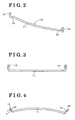
- Fig. 2 is a perspective view illustrating a wire segment according to the embodiment
- Fig. 3 is a front view illustrating the wire segment according to the embodiment
- Fig. 4 is a planar view illustrating the wire segment according to the embodiment.
- Fig. 5 is a perspective view illustrating an inner clip segment according to the embodiment, seen from a radially outer direction thereof;
- Fig. 6 is a perspective view illustrating the inner clip segment according to the embodiment, seen from a radially inner direction thereof;
- Fig. 7 is a perspective view illustrating an outer clip segment according to the embodiment, seen from a radially outer direction thereof;
- Fig. 8 is a perspective view illustrating the outer clip segment according to the embodiment, seen from the radially outer direction of the outer clip;
- Fig. 9 is a perspective view illustrating the outer clip segment according to the embodiment, seen from a radially inner direction of the outer clip;
- Fig. 10 is a front view illustrating a sub-assembly according to the embodiment, where the plurality of wire segments are attached to the inner clip;
- Fig. 11 is a perspective view illustrating a sub-assembly according to the embodiment, where wire coil is connected in a manner where the wire coil is held between the inner clip and the outer clip;
- Fig. 12 is a perspective view illustrating an entire structure of the wiring component for the motor coil.
- FIG. 12 is a perspective view illustrating an entire structure of the wiring component for the motor coil. Components and a sub-assembly are illustrated in Figs. 1 through 11 .
- First, second and third wire coils 1u,1v,1w (three wire coils are provided according to the embodiment) are configured in a manner where a plurality of wire segments 10, made of a conductive wire rod, is aligned along a circumferential direction so as to form a substantially ring shape.
- the plurality of first, second and third wire coils 1u, 1v, 1w is arranged to form a plurality of layers and thereby forming a substantially cylindrical shape.
- the inner clip 2 is formed with first, second and third ring-shaped first, second and third grooves 2u, 2v and 2w (first holding portions) at an outer circumferential surface thereof to respectively hold the first, second and third wire coils 1 u, 1v and 1w.
- the outer clip 3 is formed with ring-shaped first, second and third projecting portions 3u, 3v and 3w (second holding portions) at an inner circumferential surface thereof to respectively hold the first, second and third wire coils 1u, 1v and 1w.
- Each of the first, second and third wire coils 1 u, 1v and 1w (“the first, second and third wire coils 1u, 1v and 1w" are referred to as “wire coil 1" hereinafter) is configured by the plurality of wire segments 10 (see Figs. 2 through 4 ), which are arranged to form a substantially ring shape.
- Each of the wire segments 10 is formed with an arc-shaped main-body portion 11, protruding portions 12, 12 and the upright portions 13, 13.
- An enamel wire (a conductive wire rod), for example, is bent into an arc-shape to form the main-body portion 11. Both end portions of the main-body portion 11 are bent in the radial direction (in a radially outer direction in Fig.
- each of the protruding portions 12, 12 is bent at positions where the protruding portions 12, 12 protrude in the radial direction of the wire coil 1 by a length longer than a diameter (d) of the wire rod, in a direction vertical relative to a planar surface including the main-body portion 11, thereby the upright portions 13, 13 are formed.
- the inner clip 2 is configured by a plurality of resin-made inner clip segments 20 (first members, arc-shaped segments) (see Figs. 5 and 6 ) that are arranged and connected to each other to form a substantially cylindrical shape.
- Each of the inner clip segments 20 is formed with first, second and third first, second and third grooves 20u, 20v and 20w at an outer circumferential surface thereof.
- multiple pairs of third holding portions 23, 23 are formed at each of the inner clip segments 20.
- the third holding portions 23, 23 extend from an inner side to an outer side of the wire coil 1 in the radial direction thereof, relative to the upright portions 13, 13, at which the adjacent wire segments 10 contact each other in the circumferential direction of the wire coil 1. Protrusions 24 and engagement portions 25 will be described later.
- the outer clip 3 is configured by a plurality of resin-made outer clip segments 30 (second members, arc-shaped segments) (see Figs. 7 through 9 ), which is arranged and connected to each other to form a substantially cylindrical shape.
- each of the outer clip segments 30 is formed with first, second and third projecting portions 30u, 30v and 30w at an inner circumferential surface thereof.
- multiple pairs of vertical wall portions (sandwiching portions) 33, 33 are formed at each of the outer clip segments 30.
- the vertical wall portions 33, 33 extend from the outer side to the inner side of the wire coil 1 in the radial direction thereof, relative to the upright portions 13, 13, at which the adjacent wire segments 10 contact each other in the circumferential direction of the wire coil 1. Further, the vertical wall portions 33, 33 extend in a substantially vertical direction, relative to the planar surface including the main-body portion 11 of the wire segment 10,
- the first wire coil 1u is configured in a manner where a plurality of wire segments 10 is engaged into the first groove 2u of the inner clip 2 so as to form a ring shape.
- the second and third wire coils 1v, 1w are configured in a manner where a plurality of wire segments 10 are engaged into the second and third grooves 2v and 2w of the inner clip 2 so as to form a ring shape.
- the end portions of the protruding portions are bent at the positions where the protruding portions 12 protrude in the radial direction of the wire coil 1 by the length longer than the diameter (d) of the wire rod, and thereby the upright portions 13 are formed.
- the upright portions 13 do not contact outer circumferential surfaces of the first, second and third wire coils 1u,1v and 1w, and a thickness of the upright portions 13 is set to be smallest. Further, the upright portions 13 extend in an axial direction of the wire segments 10. Therefore, enamel coating may easily be removed at the time of electrical connection.
- extending lengths in a vertical direction of the upright portions 13, 13, at which the adjacent wire segments 10 contact each other in the circumferential direction thereof are set to vary, depending on positions where the wire segments 10 are attached to the first, second and third grooves 2u, 2v and 2w of the inner clip 2.
- the upright portions 13 are set to be the same height relative to the planar surface including the main-body portions 11 of the wire segments 10 of the wire coil 1 (the first wire coil 1 u in Fig. 1 ), arranged to be closest to a side of the upright portions 13 in an axial direction of the wire coil 1 when the first, second and third wire coils 1u, 1v and 1w are attached to the inner clip 2.
- the extending lengths of the upright portions 13, 13, at which the adjacent wire segments 10 contact each other may be set to be a predetermined length or more (for example, a predetermined length D shown in Fig. 10 or more). Then, each of the upright portions 13, 13 may be cut to be the predetermined length (D) so that each of the upright portions 13, 13 becomes the same height relative to the planar surface including the wire segments 10 of the wire coil 1 (the first wire coil 1u in Fig. 1 ), arranged to be closest to a side of the upright portions 13 in the axial direction of the wire coil 1 when the first, second and third wire coils 1u, 1v and 1w are attached to the inner clip 2.
- a plurality of terminals 40 is attached to each of the first, second and third wire coils 1u, 1v and 1w.
- Each of the terminals 40 includes a connecting portion 41 for electrically connecting the adjacent upright portions 13, 13 to the terminal 40, and a coil terminal (an extending portion) 42, extending from the connecting portion 40 in the radial direction of the wire coil 1. End portions of the wire coil 1 and the connecting portions 41 are riveted, fused, welded and the like, to be electrically connected.
- the coil terminals 42 extend in the radially inner direction of the wire coil 1 so as to be electrically connected to coil components.
- the wire segments 10 are connected to each other by means of the connecting portions 41 of the terminals 40, while the wire segments 10 are connected to the coil components by means of the coil terminals 42. Therefore, even when misalignment may occur among the wire segments 10, the misalignment may be absorbed by means of the connecting portions 41 of the terminals 40.
- three of the terminals 40 respectively include outer terminals (an extending portion) 43, extending in the radially outer direction of the wire coil 1 so as to be electrically connected to external components.
- the outer terminals 43 are formed integrally with the terminals 40.
- the outer terminals 43 may be separately formed.
- only the connecting portions 41 of the terminals 40 i.e. the protruding portions 12 and the upright portions 13 of the wire segments 10) extend outer than an outer circumference of the cylindrical shape, formed by the first, second and third wire coils 1u,1v and 1w. Therefore, less space is required. Accordingly, spaced portion, generated at a portion other than positions of the protruding potions 12 and the upright portions 13 of the wire segments 10, may be utilized to arrange fixing bolts and the like.
- each of the outer clip segments 30 includes, as illustrated in Fig. 7 , circumferential wall portions 34 and the pairs of vertical wall portions 33, 33.
- Each of the pairs of vertical wall portions 33, 33 and each of the circumferential wall portions 34 are arranged so as to form a substantially U shape, which opens toward a radially inner direction of the outer clip segments 30, when seen in a planar view.
- each of the outer clip segments 30 may be separately formed into a substantially U shape, which is formed by each of the pairs of vertical wall portions 33, 33 and each of the outer circumferential wall portions 34.
- a through-hole 35 through which each of the outer terminals 43 is inserted, is formed at the outer circumferential wall portion 34. Furthermore, a fourth holding portion 36 (see Fig. 9 ) is formed at an inner surface of each of the outer wall portions 34 to be in the vicinity of the through-hole 35. The fourth holding portion 36 press-fits the upright portions 13.
- each of the pairs of protrusions 24, 24, protruding from both sides of each of the coil terminals 42 is formed at a surface of each of the pairs of third holding portions 23, 23.
- Each of the coil terminals 42 of the terminals 40 is respectively arranged between each of the pairs of the protrusions 24, 24.
- the inner clip segments 20 are connected to each other via engagement portions 25, and thereby a sub-assembly of the cylindrically-shaped inner clip 2 is configured.
- the assembly of the wiring components is configured.
- the inner clip 2 is integrally formed to form the ring shape and the outer clip 3 is integrally formed to form the ring shape.
- the inner clip segments 20, which are formed by splitting the inner clip 2 in the circumferential direction thereof may be arranged into the cylindrical shape so as to form the inner clip 2.
- the outer clip segments 30, which are formed by splitting the outer clip 3 in the circumferential direction thereof may be arranged into the cylindrical shape so as to form the outer clip 3. In such manner, a mold for resin molding is downsized, and consequently less cost is required.
- the plurality of wire segments 10 are arranged in the circumferential direction so as to form the ring-shaped wire coil 1. Further, the plurality of first, second and third wire coils 1u, 1v and 1w are arranged in layers so as to form the cylindrical shape.
- the upright portions 13, at which the adjacent wire segments 10 contact each other in the circumferential direction thereof, are electrically connected to each other. Therefore, a complicated bending process may not be required, and the wire segments 10 may be easily formed by means of a simple bending mold, thereby reducing cost.
- only the protruding portions 12 and the upright portions 13 extend outer than the outer circumferential surface of the cylindrically-shaped wire coil 1. Therefore, less space is required, and a spaced portion, generated at a portion other than positions of the protruding potions 12 and the upright portions 13, may be utilized to arrange fixing bolts and the like.
- extending lengths of the upright portions 13, at which the adjacent wire segments 10 contact each other in the circumferential direction of the wire segments 10, are set to vary, depending on positions where the wire coil 1, 1u, 1v and 1w is arranged to form the plurality of layers, and the upright portions 13 are set to be the same height relative to the planar surface including the main-body portions 11 of the wire coil 1, 1u,1v and 1w, arranged at to be closest to a side of the upright portions 13 in an axial direction when the wire coil 1, 1u, 1v and 1w is arranged in the plurality of layers so as to form the cylindrical shape.
- an extending length of each of the upright portions 13, at which the adjacent wire segments 10 contact each other is set to be a predetermined length D or more, and each of the upright portions 13 is cut to be the predetermined length D so that the upright portions 13 become the same height relative to the planar surface including the wire coil 1, 1 u, 1v and 1w, arranged to be closest to a side of the upright portions 13 in an axial direction when the wire coil 1, 1u, 1v and 1w is arranged in the plurality of layers so as to form the cylindrical shape.
- the wire segments 10 differ from each other only in the extending lengths of the upright portions 13 thereof. Therefore, only cutting lengths of the upright portions 13 may be set to be different, and as a result, the wire segments 10 may be manufactured easily. Alternatively, the wire segments 10 may be formed into the same shape, and unnecessary portions may be cut later. As a result, the wire segments 10 may be manufactured easily.
- the wiring component for the motor coil further includes the plurality of terminals 40, each of which including a connecting portion 41 electrically connecting the upright portions 13, at which the adjacent wire segments 10 contact each other in the circumferential direction thereof, and at least one extending portion 42 and 43 extending from the connecting portion 41 in a radial direction of the wire coil 1, 1u, 1v and 1w.
- the upright portions 13 are electrically connected to each other by means of the terminals 40.
- the extending portion 42 and 43 is the coil terminal 42 extending in a radially inner direction of the wire coil 1, 1u, 1v and 1w so as to be electrically connected to a coil component.
- the extending portion 42 and 43 is the outer terminal 43 extending in a radially outer direction of the wire coil 1, 1u, 1v and 1w so as to be electrically connected to an external component.
- the terminals 40 and the wire coil 1 are electrically connected to each other easily and surely, and the misalignment, which may occur at the time of connecting the wire segments 10, may be absorbed.
- the extending portion 42 and 43 of the terminal 40 may serve as the coil terminals 42 for electrically connecting the terminal 40 to the coil components, or the outer terminals 43 for electrically connecting the terminals 40 to the external components.
- a wiring component for a motor coil includes a wire coil (1, 1 u, 1v,1w) configured by a plurality of wire segments (10) arranged in a circumferential direction so as to form a ring shape, each of the wire segments (10) including an arc-shaped main-body portion (11) made of a conductive wire rod bent in an arc shape, protruding portions (12) formed at both end portions of the main-body portion (11), and upright portions (13) respectively formed at end portions of the protruding portions (12) in a manner of bending one of end portions of each of the protruding portions (12) so that the upright portions (13) protrude in a direction vertical relative to a planar surface including the main-body portions (11).
- the wire coil (1, 1u,1v, 1w) is arranged to form a plurality of layers, thereby forming a cylindrical shape, and the upright portions (13), at which the adjacent wire segments (10) contact each other in the circumferential direction thereof, are electrically connected to each other.
Landscapes
- Engineering & Computer Science (AREA)
- Power Engineering (AREA)
- Insulation, Fastening Of Motor, Generator Windings (AREA)
- Windings For Motors And Generators (AREA)
Claims (5)
- Composant de câblage destiné à une bobine de moteur comprenant :une bobine de fil (1, 1u, 1v, 1w) configurée par une pluralité de segments de fil (10) agencés dans une direction circonférentielle de manière à former une forme annulaire, chacun des segments de fil (10) comportant une partie de corps principal en forme d'arc (11) constituée d'une tige en fil conducteur pliée en forme d'arc, des parties en saillie (12) formées au niveau des deux parties d'extrémité de la partie de corps principal (11) de manière à plier les deux parties d'extrémité de la partie de corps principal (11) dans une direction radiale, dans lequella bobine de fil (1, 1u, 1v, 1w) est agencée pour former une pluralité de couches, formant ainsi une forme cylindrique ; caractérisé pardes parties verticales (13) formées respectivement au niveau de parties d'extrémité des parties en saillie (12) de manière à plier l'une des parties d'extrémité de chacune des parties en saillie (12) à des positions où les parties en saillie (12) font saillie dans une direction radiale par une longueur supérieure au diamètre (d) de la tige en fil conducteur, de sorte que les parties verticales (13) fassent saillie dans une direction verticale par rapport à une surface planaire comportant la partie de corps principal (11), dans lequelles parties verticales (13), au niveau desquelles les segments de fil adjacents (10) sont en contact dans leur direction circonférentielle, sont électriquement reliées les unes aux autres, etune pluralité de bornes (40), dont chacune comporte une partie de connexion (41) reliant électriquement les parties verticales (13), au niveau desquelles les segments de fil adjacents (10) sont en contact dans leur direction circonférentielle, et au moins une partie d'extension (42, 43) s'étendant depuis la partie de connexion (41) dans une direction radiale de la bobine de fil (1, 1u, 1v, 1w), où les parties verticales (13) sont électriquement reliées les unes aux autres au moyen des bornes (40).
- Composant de câblage destiné à la bobine de moteur selon la revendication 1, dans lequel des longueurs d'extension des parties verticales (13), au niveau desquelles les segments de fils adjacents (10) sont en contact dans la direction circonférentielle des segments de fil (10), sont réglées pour être variées en fonction des positions où la bobine de fil (1, 1u, 1v, 1w) est agencée pour former la pluralité de couches, et les parties verticales (13) sont réglées pour être à la même hauteur par rapport à la surface planaire comportant les parties de corps principal (11) de la bobine de fil (1, 1u, 1v, 1w), agencées pour être les plus proches d'un côté des parties verticales (13) dans une direction axiale lorsque la bobine de fil (1, 1u, 1v, 1w) est agencée dans la pluralité de couches afin de former la forme cylindrique.
- Composant de câblage destiné à la bobine de moteur selon la revendication 1, dans lequel une longueur d'extension de chacune des parties verticales (13), au niveau desquelles les segments de fil adjacents (10) sont en contact, est réglée pour être supérieure ou égale à une longueur prédéterminée (D), et chacune des parties verticales (13) est découpée pour être égale à la longueur prédéterminée (D) de sorte que les parties verticales (13) deviennent à la même hauteur par rapport à la surface planaire comportant la bobine de fil (1, 1u, 1v, 1w), agencée pour être la plus proche d'un côté des parties verticales (13) dans une direction axiale lorsque la bobine de fil (1, 1u, 1v, 1w) est agencée dans la pluralité de couches afin de former la forme cylindrique.
- Composant de câblage destiné à la bobine de moteur selon la revendication 1, dans lequel la partie d'extension (42, 43) est une borne (42) de la bobine s'étendant dans une direction radialement intérieure de la bobine de fil (1, 1u, 1v, 1w) de manière à être électriquement reliée à un composant de la bobine.
- Composant de câblage destiné à la bobine de moteur selon la revendication 1, dans lequel la partie d'extension (42, 43) est une borne extérieure (43) s'étendant dans une direction radialement extérieure de la bobine de fil (1, 1u, 1v, 1w) de manière à être électriquement reliée à un composant externe.
Applications Claiming Priority (1)
| Application Number | Priority Date | Filing Date | Title |
|---|---|---|---|
| JP2008280684A JP2010110144A (ja) | 2008-10-31 | 2008-10-31 | モータコイルの配線部品 |
Publications (3)
| Publication Number | Publication Date |
|---|---|
| EP2182615A2 EP2182615A2 (fr) | 2010-05-05 |
| EP2182615A3 EP2182615A3 (fr) | 2011-11-16 |
| EP2182615B1 true EP2182615B1 (fr) | 2013-04-03 |
Family
ID=41665052
Family Applications (1)
| Application Number | Title | Priority Date | Filing Date |
|---|---|---|---|
| EP09174307A Not-in-force EP2182615B1 (fr) | 2008-10-31 | 2009-10-28 | Composant de câblage de bobine de moteur |
Country Status (4)
| Country | Link |
|---|---|
| US (1) | US8217541B2 (fr) |
| EP (1) | EP2182615B1 (fr) |
| JP (1) | JP2010110144A (fr) |
| CN (1) | CN101728887B (fr) |
Families Citing this family (15)
| Publication number | Priority date | Publication date | Assignee | Title |
|---|---|---|---|---|
| IT1397784B1 (it) * | 2010-01-15 | 2013-01-24 | Gate Srl | Collettore per lo statore di un motore brushless in corrente continua a magneti permanenti |
| JP2012005326A (ja) | 2010-06-21 | 2012-01-05 | Aisin Seiki Co Ltd | 車両用回転電機の配線部品 |
| EP2413478B1 (fr) * | 2010-07-27 | 2017-11-22 | General Electric Technology GmbH | Ensemble formant anneau de phase |
| FR2991830B1 (fr) * | 2012-06-12 | 2014-06-06 | Valeo Equip Electr Moteur | Element pour le maintien de fils de bobinage d'un stator de machine electrique |
| FR2991831B1 (fr) * | 2012-06-12 | 2015-07-24 | Valeo Equip Electr Moteur | Element isolant pour stator de machine electrique |
| FR2995472B1 (fr) * | 2012-09-12 | 2015-10-16 | Valeo Equip Electr Moteur | Interconnecteur pour stator de machine electrique, cache isolant, et stator de machine electrique correspondants |
| JP6444653B2 (ja) * | 2014-08-18 | 2018-12-26 | 愛三工業株式会社 | ステータ及び電動ポンプ |
| CN107093936A (zh) * | 2016-02-18 | 2017-08-25 | 德昌电机(深圳)有限公司 | 端盖组件及具有该端盖组件的定子 |
| KR101871594B1 (ko) * | 2016-11-11 | 2018-06-26 | 엘에스오토모티브테크놀로지스 주식회사 | 디스트리뷰션 와이어 유니트 |
| KR101871596B1 (ko) * | 2016-11-11 | 2018-06-26 | 엘에스오토모티브테크놀로지스 주식회사 | 디스트리뷰션 와이어 유니트 |
| KR101871595B1 (ko) * | 2016-11-11 | 2018-06-26 | 엘에스오토모티브테크놀로지스 주식회사 | 디스트리뷰션 와이어 유니트 |
| JP6589936B2 (ja) * | 2017-05-31 | 2019-10-16 | 日立金属株式会社 | 配線構造 |
| DE102018102033A1 (de) * | 2018-01-30 | 2019-08-01 | Ebm-Papst St. Georgen Gmbh & Co. Kg | Statorvorrichtung mit Verschalt-Endscheibe für einen Elektromotor und Verwendung der Statorvorrichtung |
| US11532964B2 (en) * | 2020-01-22 | 2022-12-20 | Hamilton Sundstrand Corporation | Generator rotor flat wire winding |
| CN118739685A (zh) * | 2023-03-31 | 2024-10-01 | 台达电子工业股份有限公司 | 定子及其端子固定结构 |
Family Cites Families (9)
| Publication number | Priority date | Publication date | Assignee | Title |
|---|---|---|---|---|
| JPH05300687A (ja) * | 1992-04-16 | 1993-11-12 | Seiko Epson Corp | モータ及びモータの製造方法 |
| JP3430839B2 (ja) * | 1997-03-03 | 2003-07-28 | 松下電器産業株式会社 | 固定子の結線構造 |
| JP3681366B2 (ja) * | 2002-08-21 | 2005-08-10 | 日立電線株式会社 | 配電部品及びその製造方法 |
| JP3701639B2 (ja) * | 2002-08-29 | 2005-10-05 | 本田技研工業株式会社 | 電動機のリードフレーム及びこれを用いた配電部品 |
| JP2005045903A (ja) * | 2003-07-28 | 2005-02-17 | Sumitomo Wiring Syst Ltd | 車両用薄型ブラシモータの集中配電部材及び車両用薄型ブラシモータの集中配電部材の製造方法 |
| JP4244008B2 (ja) | 2003-11-20 | 2009-03-25 | 住友電装株式会社 | モータ用集中配電部材 |
| JP4758798B2 (ja) * | 2006-03-24 | 2011-08-31 | 住友電気工業株式会社 | 回転電機のステ―タ用バスバ結合ユニット |
| JP2007295698A (ja) * | 2006-04-24 | 2007-11-08 | Toyota Motor Corp | 回転電機の固定子 |
| JP2008061345A (ja) * | 2006-08-30 | 2008-03-13 | Sumitomo Wiring Syst Ltd | モータ用集中配電部材 |
-
2008
- 2008-10-31 JP JP2008280684A patent/JP2010110144A/ja active Pending
-
2009
- 2009-10-28 EP EP09174307A patent/EP2182615B1/fr not_active Not-in-force
- 2009-10-30 CN CN200910205597.2A patent/CN101728887B/zh not_active Expired - Fee Related
- 2009-10-30 US US12/609,278 patent/US8217541B2/en not_active Expired - Fee Related
Also Published As
| Publication number | Publication date |
|---|---|
| US8217541B2 (en) | 2012-07-10 |
| CN101728887A (zh) | 2010-06-09 |
| EP2182615A3 (fr) | 2011-11-16 |
| EP2182615A2 (fr) | 2010-05-05 |
| JP2010110144A (ja) | 2010-05-13 |
| CN101728887B (zh) | 2014-03-26 |
| US20100109457A1 (en) | 2010-05-06 |
Similar Documents
| Publication | Publication Date | Title |
|---|---|---|
| EP2182615B1 (fr) | Composant de câblage de bobine de moteur | |
| EP2182614B1 (fr) | Composant de câblage de bobine de moteur | |
| EP2596567B1 (fr) | Appareil de distribution de puissance moteur | |
| US8497618B2 (en) | Stator for rotatry electrical machine including an insulating bobbin | |
| EP3095176B1 (fr) | Stator de machine électrique rotative | |
| CN105210267B (zh) | 旋转电机及其制造方法 | |
| US9577498B2 (en) | Stator for rotary electric machine and method for manufacturing the stator | |
| EP2827476B1 (fr) | Stator et procédé de fabrication de stator | |
| JP4270307B2 (ja) | 渡り線モジュール | |
| CN113615047B (zh) | 定子及电动机 | |
| US20160218578A1 (en) | Bus bar unit, method for manufacturing bus bar unit, and brushless motor | |
| JP2007174869A (ja) | インシュレータ、ステータアセンブリ、セグメントステータ、及び回転電機用ステータ | |
| EP3872968A1 (fr) | Moteur | |
| JP4465396B2 (ja) | 回転電機の配電接続構造および回転電機の配電接続構造の製造方法 | |
| JP4913538B2 (ja) | 集中配電部品 | |
| JP5144180B2 (ja) | ステータの中点連結構造 | |
| CN113228467B (zh) | 电动机 | |
| JP2025066396A (ja) | ステータユニット及びこれを備えるモータ |
Legal Events
| Date | Code | Title | Description |
|---|---|---|---|
| PUAI | Public reference made under article 153(3) epc to a published international application that has entered the european phase |
Free format text: ORIGINAL CODE: 0009012 |
|
| AK | Designated contracting states |
Kind code of ref document: A2 Designated state(s): AT BE BG CH CY CZ DE DK EE ES FI FR GB GR HR HU IE IS IT LI LT LU LV MC MK MT NL NO PL PT RO SE SI SK SM TR |
|
| AX | Request for extension of the european patent |
Extension state: AL BA RS |
|
| PUAL | Search report despatched |
Free format text: ORIGINAL CODE: 0009013 |
|
| AK | Designated contracting states |
Kind code of ref document: A3 Designated state(s): AT BE BG CH CY CZ DE DK EE ES FI FR GB GR HR HU IE IS IT LI LT LU LV MC MK MT NL NO PL PT RO SE SI SK SM TR |
|
| AX | Request for extension of the european patent |
Extension state: AL BA RS |
|
| RIC1 | Information provided on ipc code assigned before grant |
Ipc: H02K 3/50 20060101AFI20111013BHEP |
|
| 17P | Request for examination filed |
Effective date: 20120416 |
|
| GRAP | Despatch of communication of intention to grant a patent |
Free format text: ORIGINAL CODE: EPIDOSNIGR1 |
|
| GRAS | Grant fee paid |
Free format text: ORIGINAL CODE: EPIDOSNIGR3 |
|
| GRAA | (expected) grant |
Free format text: ORIGINAL CODE: 0009210 |
|
| AK | Designated contracting states |
Kind code of ref document: B1 Designated state(s): AT BE BG CH CY CZ DE DK EE ES FI FR GB GR HR HU IE IS IT LI LT LU LV MC MK MT NL NO PL PT RO SE SI SK SM TR |
|
| REG | Reference to a national code |
Ref country code: GB Ref legal event code: FG4D |
|
| REG | Reference to a national code |
Ref country code: AT Ref legal event code: REF Ref document number: 605246 Country of ref document: AT Kind code of ref document: T Effective date: 20130415 Ref country code: CH Ref legal event code: EP |
|
| REG | Reference to a national code |
Ref country code: IE Ref legal event code: FG4D |
|
| REG | Reference to a national code |
Ref country code: DE Ref legal event code: R096 Ref document number: 602009014599 Country of ref document: DE Effective date: 20130529 |
|
| REG | Reference to a national code |
Ref country code: AT Ref legal event code: MK05 Ref document number: 605246 Country of ref document: AT Kind code of ref document: T Effective date: 20130403 |
|
| PG25 | Lapsed in a contracting state [announced via postgrant information from national office to epo] |
Ref country code: SI Free format text: LAPSE BECAUSE OF FAILURE TO SUBMIT A TRANSLATION OF THE DESCRIPTION OR TO PAY THE FEE WITHIN THE PRESCRIBED TIME-LIMIT Effective date: 20130403 |
|
| REG | Reference to a national code |
Ref country code: NL Ref legal event code: VDEP Effective date: 20130403 |
|
| REG | Reference to a national code |
Ref country code: LT Ref legal event code: MG4D |
|
| PG25 | Lapsed in a contracting state [announced via postgrant information from national office to epo] |
Ref country code: LT Free format text: LAPSE BECAUSE OF FAILURE TO SUBMIT A TRANSLATION OF THE DESCRIPTION OR TO PAY THE FEE WITHIN THE PRESCRIBED TIME-LIMIT Effective date: 20130403 Ref country code: BE Free format text: LAPSE BECAUSE OF FAILURE TO SUBMIT A TRANSLATION OF THE DESCRIPTION OR TO PAY THE FEE WITHIN THE PRESCRIBED TIME-LIMIT Effective date: 20130403 Ref country code: FI Free format text: LAPSE BECAUSE OF FAILURE TO SUBMIT A TRANSLATION OF THE DESCRIPTION OR TO PAY THE FEE WITHIN THE PRESCRIBED TIME-LIMIT Effective date: 20130403 Ref country code: GR Free format text: LAPSE BECAUSE OF FAILURE TO SUBMIT A TRANSLATION OF THE DESCRIPTION OR TO PAY THE FEE WITHIN THE PRESCRIBED TIME-LIMIT Effective date: 20130704 Ref country code: IS Free format text: LAPSE BECAUSE OF FAILURE TO SUBMIT A TRANSLATION OF THE DESCRIPTION OR TO PAY THE FEE WITHIN THE PRESCRIBED TIME-LIMIT Effective date: 20130803 Ref country code: SE Free format text: LAPSE BECAUSE OF FAILURE TO SUBMIT A TRANSLATION OF THE DESCRIPTION OR TO PAY THE FEE WITHIN THE PRESCRIBED TIME-LIMIT Effective date: 20130403 Ref country code: PT Free format text: LAPSE BECAUSE OF FAILURE TO SUBMIT A TRANSLATION OF THE DESCRIPTION OR TO PAY THE FEE WITHIN THE PRESCRIBED TIME-LIMIT Effective date: 20130805 Ref country code: NL Free format text: LAPSE BECAUSE OF FAILURE TO SUBMIT A TRANSLATION OF THE DESCRIPTION OR TO PAY THE FEE WITHIN THE PRESCRIBED TIME-LIMIT Effective date: 20130403 Ref country code: ES Free format text: LAPSE BECAUSE OF FAILURE TO SUBMIT A TRANSLATION OF THE DESCRIPTION OR TO PAY THE FEE WITHIN THE PRESCRIBED TIME-LIMIT Effective date: 20130714 Ref country code: NO Free format text: LAPSE BECAUSE OF FAILURE TO SUBMIT A TRANSLATION OF THE DESCRIPTION OR TO PAY THE FEE WITHIN THE PRESCRIBED TIME-LIMIT Effective date: 20130703 Ref country code: AT Free format text: LAPSE BECAUSE OF FAILURE TO SUBMIT A TRANSLATION OF THE DESCRIPTION OR TO PAY THE FEE WITHIN THE PRESCRIBED TIME-LIMIT Effective date: 20130403 |
|
| PG25 | Lapsed in a contracting state [announced via postgrant information from national office to epo] |
Ref country code: BG Free format text: LAPSE BECAUSE OF FAILURE TO SUBMIT A TRANSLATION OF THE DESCRIPTION OR TO PAY THE FEE WITHIN THE PRESCRIBED TIME-LIMIT Effective date: 20130703 Ref country code: CY Free format text: LAPSE BECAUSE OF FAILURE TO SUBMIT A TRANSLATION OF THE DESCRIPTION OR TO PAY THE FEE WITHIN THE PRESCRIBED TIME-LIMIT Effective date: 20130403 Ref country code: LV Free format text: LAPSE BECAUSE OF FAILURE TO SUBMIT A TRANSLATION OF THE DESCRIPTION OR TO PAY THE FEE WITHIN THE PRESCRIBED TIME-LIMIT Effective date: 20130403 Ref country code: HR Free format text: LAPSE BECAUSE OF FAILURE TO SUBMIT A TRANSLATION OF THE DESCRIPTION OR TO PAY THE FEE WITHIN THE PRESCRIBED TIME-LIMIT Effective date: 20130403 Ref country code: PL Free format text: LAPSE BECAUSE OF FAILURE TO SUBMIT A TRANSLATION OF THE DESCRIPTION OR TO PAY THE FEE WITHIN THE PRESCRIBED TIME-LIMIT Effective date: 20130403 |
|
| PG25 | Lapsed in a contracting state [announced via postgrant information from national office to epo] |
Ref country code: DK Free format text: LAPSE BECAUSE OF FAILURE TO SUBMIT A TRANSLATION OF THE DESCRIPTION OR TO PAY THE FEE WITHIN THE PRESCRIBED TIME-LIMIT Effective date: 20130403 Ref country code: EE Free format text: LAPSE BECAUSE OF FAILURE TO SUBMIT A TRANSLATION OF THE DESCRIPTION OR TO PAY THE FEE WITHIN THE PRESCRIBED TIME-LIMIT Effective date: 20130403 Ref country code: SK Free format text: LAPSE BECAUSE OF FAILURE TO SUBMIT A TRANSLATION OF THE DESCRIPTION OR TO PAY THE FEE WITHIN THE PRESCRIBED TIME-LIMIT Effective date: 20130403 Ref country code: CZ Free format text: LAPSE BECAUSE OF FAILURE TO SUBMIT A TRANSLATION OF THE DESCRIPTION OR TO PAY THE FEE WITHIN THE PRESCRIBED TIME-LIMIT Effective date: 20130403 |
|
| PGFP | Annual fee paid to national office [announced via postgrant information from national office to epo] |
Ref country code: FR Payment date: 20131009 Year of fee payment: 5 Ref country code: DE Payment date: 20131023 Year of fee payment: 5 |
|
| PLBE | No opposition filed within time limit |
Free format text: ORIGINAL CODE: 0009261 |
|
| STAA | Information on the status of an ep patent application or granted ep patent |
Free format text: STATUS: NO OPPOSITION FILED WITHIN TIME LIMIT |
|
| PG25 | Lapsed in a contracting state [announced via postgrant information from national office to epo] |
Ref country code: IT Free format text: LAPSE BECAUSE OF FAILURE TO SUBMIT A TRANSLATION OF THE DESCRIPTION OR TO PAY THE FEE WITHIN THE PRESCRIBED TIME-LIMIT Effective date: 20130403 Ref country code: RO Free format text: LAPSE BECAUSE OF FAILURE TO SUBMIT A TRANSLATION OF THE DESCRIPTION OR TO PAY THE FEE WITHIN THE PRESCRIBED TIME-LIMIT Effective date: 20130403 |
|
| 26N | No opposition filed |
Effective date: 20140106 |
|
| REG | Reference to a national code |
Ref country code: DE Ref legal event code: R097 Ref document number: 602009014599 Country of ref document: DE Effective date: 20140106 |
|
| PG25 | Lapsed in a contracting state [announced via postgrant information from national office to epo] |
Ref country code: MC Free format text: LAPSE BECAUSE OF FAILURE TO SUBMIT A TRANSLATION OF THE DESCRIPTION OR TO PAY THE FEE WITHIN THE PRESCRIBED TIME-LIMIT Effective date: 20130403 |
|
| REG | Reference to a national code |
Ref country code: CH Ref legal event code: PL |
|
| GBPC | Gb: european patent ceased through non-payment of renewal fee |
Effective date: 20131028 |
|
| REG | Reference to a national code |
Ref country code: IE Ref legal event code: MM4A |
|
| PG25 | Lapsed in a contracting state [announced via postgrant information from national office to epo] |
Ref country code: CH Free format text: LAPSE BECAUSE OF NON-PAYMENT OF DUE FEES Effective date: 20131031 Ref country code: GB Free format text: LAPSE BECAUSE OF NON-PAYMENT OF DUE FEES Effective date: 20131028 Ref country code: LI Free format text: LAPSE BECAUSE OF NON-PAYMENT OF DUE FEES Effective date: 20131031 |
|
| PG25 | Lapsed in a contracting state [announced via postgrant information from national office to epo] |
Ref country code: IE Free format text: LAPSE BECAUSE OF NON-PAYMENT OF DUE FEES Effective date: 20131028 |
|
| REG | Reference to a national code |
Ref country code: DE Ref legal event code: R119 Ref document number: 602009014599 Country of ref document: DE |
|
| PG25 | Lapsed in a contracting state [announced via postgrant information from national office to epo] |
Ref country code: SM Free format text: LAPSE BECAUSE OF FAILURE TO SUBMIT A TRANSLATION OF THE DESCRIPTION OR TO PAY THE FEE WITHIN THE PRESCRIBED TIME-LIMIT Effective date: 20130403 |
|
| PG25 | Lapsed in a contracting state [announced via postgrant information from national office to epo] |
Ref country code: TR Free format text: LAPSE BECAUSE OF FAILURE TO SUBMIT A TRANSLATION OF THE DESCRIPTION OR TO PAY THE FEE WITHIN THE PRESCRIBED TIME-LIMIT Effective date: 20130403 |
|
| PG25 | Lapsed in a contracting state [announced via postgrant information from national office to epo] |
Ref country code: MK Free format text: LAPSE BECAUSE OF FAILURE TO SUBMIT A TRANSLATION OF THE DESCRIPTION OR TO PAY THE FEE WITHIN THE PRESCRIBED TIME-LIMIT Effective date: 20130403 Ref country code: DE Free format text: LAPSE BECAUSE OF NON-PAYMENT OF DUE FEES Effective date: 20150501 Ref country code: LU Free format text: LAPSE BECAUSE OF NON-PAYMENT OF DUE FEES Effective date: 20131028 Ref country code: HU Free format text: LAPSE BECAUSE OF FAILURE TO SUBMIT A TRANSLATION OF THE DESCRIPTION OR TO PAY THE FEE WITHIN THE PRESCRIBED TIME-LIMIT; INVALID AB INITIO Effective date: 20091028 |
|
| REG | Reference to a national code |
Ref country code: FR Ref legal event code: ST Effective date: 20150630 |
|
| PG25 | Lapsed in a contracting state [announced via postgrant information from national office to epo] |
Ref country code: MT Free format text: LAPSE BECAUSE OF FAILURE TO SUBMIT A TRANSLATION OF THE DESCRIPTION OR TO PAY THE FEE WITHIN THE PRESCRIBED TIME-LIMIT Effective date: 20130403 Ref country code: FR Free format text: LAPSE BECAUSE OF NON-PAYMENT OF DUE FEES Effective date: 20141031 |