EP2183146B1 - Poussette pourvue d'au moins une poignée réglable - Google Patents
Poussette pourvue d'au moins une poignée réglable Download PDFInfo
- Publication number
- EP2183146B1 EP2183146B1 EP08785074A EP08785074A EP2183146B1 EP 2183146 B1 EP2183146 B1 EP 2183146B1 EP 08785074 A EP08785074 A EP 08785074A EP 08785074 A EP08785074 A EP 08785074A EP 2183146 B1 EP2183146 B1 EP 2183146B1
- Authority
- EP
- European Patent Office
- Prior art keywords
- tube
- baby carriage
- traction means
- sleeve
- stroller according
- Prior art date
- Legal status (The legal status is an assumption and is not a legal conclusion. Google has not performed a legal analysis and makes no representation as to the accuracy of the status listed.)
- Not-in-force
Links
Images



Classifications
-
- B—PERFORMING OPERATIONS; TRANSPORTING
- B62—LAND VEHICLES FOR TRAVELLING OTHERWISE THAN ON RAILS
- B62B—HAND-PROPELLED VEHICLES, e.g. HAND CARTS OR PERAMBULATORS; SLEDGES
- B62B9/00—Accessories or details specially adapted for children's carriages or perambulators
- B62B9/20—Handle bars; Handles
-
- F—MECHANICAL ENGINEERING; LIGHTING; HEATING; WEAPONS; BLASTING
- F16—ENGINEERING ELEMENTS AND UNITS; GENERAL MEASURES FOR PRODUCING AND MAINTAINING EFFECTIVE FUNCTIONING OF MACHINES OR INSTALLATIONS; THERMAL INSULATION IN GENERAL
- F16B—DEVICES FOR FASTENING OR SECURING CONSTRUCTIONAL ELEMENTS OR MACHINE PARTS TOGETHER, e.g. NAILS, BOLTS, CIRCLIPS, CLAMPS, CLIPS OR WEDGES; JOINTS OR JOINTING
- F16B7/00—Connections of rods or tubes, e.g. of non-circular section, mutually, including resilient connections
- F16B7/10—Telescoping systems
- F16B7/14—Telescoping systems locking in intermediate non-discrete positions
- F16B7/1445—Telescoping systems locking in intermediate non-discrete positions with a rubber bushing gripping inside the outer telescoping member by a radial expansion due to its axial compression
-
- B—PERFORMING OPERATIONS; TRANSPORTING
- B62—LAND VEHICLES FOR TRAVELLING OTHERWISE THAN ON RAILS
- B62B—HAND-PROPELLED VEHICLES, e.g. HAND CARTS OR PERAMBULATORS; SLEDGES
- B62B5/00—Accessories or details specially adapted for hand carts
- B62B5/06—Hand moving equipment, e.g. handle bars
- B62B5/064—Hand moving equipment, e.g. handle bars adaptable for different users, e.g. by means of pivoting elements
-
- B—PERFORMING OPERATIONS; TRANSPORTING
- B62—LAND VEHICLES FOR TRAVELLING OTHERWISE THAN ON RAILS
- B62B—HAND-PROPELLED VEHICLES, e.g. HAND CARTS OR PERAMBULATORS; SLEDGES
- B62B5/00—Accessories or details specially adapted for hand carts
- B62B5/06—Hand moving equipment, e.g. handle bars
- B62B5/064—Hand moving equipment, e.g. handle bars adaptable for different users, e.g. by means of pivoting elements
- B62B5/065—Hand moving equipment, e.g. handle bars adaptable for different users, e.g. by means of pivoting elements by means of telescopic elements
-
- B—PERFORMING OPERATIONS; TRANSPORTING
- B62—LAND VEHICLES FOR TRAVELLING OTHERWISE THAN ON RAILS
- B62B—HAND-PROPELLED VEHICLES, e.g. HAND CARTS OR PERAMBULATORS; SLEDGES
- B62B5/00—Accessories or details specially adapted for hand carts
- B62B5/06—Hand moving equipment, e.g. handle bars
- B62B5/066—Handle bars rotatable about their longitudinal axis
Definitions
- independent claim 1 and independent claim 2 is directed to a stroller, buggy or the like having a frame, a plurality of wheels, a cap and at least one height-adjustable handle.
- a suitable mechanism should not unnecessarily increase the price of the stroller or buggy.
- the handle (s) is / are coupled or connected to at least one (each) one tube of the frame, whose cross-section (e) is (slightly) smaller in a first state is / are as the inner cross-section of the tube, and in a second state at least partially outwardly pressable or spreadable / to be clamped within the tube.
- the handle can be clamped in any height position and / or rotational position and thus adjusted continuously.
- This adjustment mechanism is also relatively simple and therefore inexpensive. It is also suitable for installation in a tube of a stroller or child buggy chassis.
- At least one adjustable element is designed as an elastic ring, its outer circumference can be pressed apart in the radial direction forcefully.
- a ring i.e., a doubly connected body, experiences, in contrast to a body which is only simply connected, only indirectly a force acting counter to the radial expansion, namely as a result of an internal stress counteracting the enlargement of its circumference.
- the elasticity of the body allows this a wide, non-destructive stretching already at a relatively low voltage.
- a radially outward force could be initiated directly on the inside of a ring. Such a radial spread would build up a radial pressure within the annular body and thus force the outer jacket thereof outwards.
- the DE 199 35802 describes such a stroller and discloses all the features of the preambles of the independent expressions 1 and 2.
- the handles of a stroller or buggy by means of a low-cost mechanics universal, easy and quick adjustable and lockable to make, the mechanics for a connection or a mounting or installation on / in a Tube of a stroller or buggy chassis should be suitable.
- At least one elastic ring can be acted upon with an axial pressure.
- This measure also leads in the end to a radial spread of the outer shell, since the annular body tries to avoid an axial compression by stretching in the radial direction, while maintaining its (radial) proportions, which is possible only in conjunction with an increase in its outer circumference. (Largely) homogeneous (elasticity) properties of the annular body allow the conversion of a relatively low voltage into a relatively strong, non-destructive deformation.
- an axial pressure between the two end faces of the annular body with two in the axial direction mutually adjustable elements can be between ends of the annular body is located and can be clamped if necessary.
- the two mutually axially adjustable elements are arranged concentrically to each other, corresponding to the approximately constant cross-section of a tube of the chassis of a baby carriage or buggy.
- the clamping elements may each be disk-shaped, in particular circular-disk-shaped or ring-disk-shaped or annular bodies, preferably of metal or of a similar solid or stiff material.
- a preferred feature of the invention is that the distance of the expandable body to the handle or its connecting joint is constant, i. is fixed.
- the expandable body is adjustable together with the handle, including the spreader axially encompassing and possibly together pressing elements. This can be accomplished by connecting both thrust generating bodies to the adjustable handle assembly. Such a connection can, for example, by means of rods and / or pipes, possibly also with a wire or other traction means, causes.
- an arrangement is to give preference, with one of the two mutually adjustable elements as a tube, sleeve od. Like. And the other as this tubular or sleeve-shaped element sweeping rod, tube, and / or as a wire or other traction means is formed.
- a rod, pipe or the like which penetrates the expandable body should be located beyond, i. extend cross-section below the / the elastic ring (-e), for example, by a screwed-on disc to engage under an annular lower end face of the expandable body.
- the invention recommends that the rod has a different cross-section from the circular shape, for example.
- Such a design specification takes into account that radially outermost regions of a connection profile are more resistant to torsion than further inner regions.
- An ideal cross-sectional shape are, for example, connecting pipes. Such a geometry should therefore also have a central connection profile.
- a central rod, tube or the like should be displaceable in the axial direction relative to one (or one of these) the surrounding tube, sleeve or the like.
- the locking or adjustment state of the expandable body can be arranged at the upper end of a rod, sleeve and / or pipe, in particular articulated or molded lever serve. This can be realized, for example, by the fact that the pivoting, rotating and / or other position of the lever is coupled to a device for changing the pressure on or in the expandable body in order to pass on this information.
- the pivot axis of the lever is aligned transversely to the longitudinal axis of the rod and / or the sleeve, since such a movement of the expandable body through the guide tube of the stroller frame is impossible.
- the adjustment movement of the handle of the selection movement of the lever is kinematically completely decoupled, making it possible to integrate these two elements - handle and selector lever - together to form an assembly or even a single part.
- At least one lever may have at its articulated end a jacket section which surrounds the pivot axis at least partially along its longitudinal direction. This can be used to implement a change in the pivot angle of the selector lever in an (approximately) axial displacement of a passing with the lateral surface in contact member.
- the surrounding the pivot axis shell portion may be so eccentric to this pivot axis, so that changes the distance of its circumference of the pivot axis cam-shaped in the circumferential direction.
- cam-shaped peripheral portion od on an end portion of the sleeve.
- a tension element can be provided in order to pull up a pressure element, preferably the lower, in a specific angular position of the selector lever and thus exert (also) pressure on the relevant, namely lower surface of the expandable body.
- a tension element may optionally be designed as a rod, tube or as a wire or other flexible, but only slightly or not at all extensible traction means.
- a cuff enclosing the same outside is arranged, which is fixable in and / or on the guide tube, for example. Engages in recesses thereof or engages through the same and / or engages around the outside of the guide tube.
- a closure cap which serves to guide the sleeve.
- a closure cap may be formed latched in recesses of the guide tube and / or the same above and / or outside over and / or surrounds.
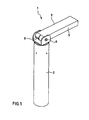
- a commercial stroller buggy od. Like. Equipped with two handle units 1, which are guided longitudinally displaceable and lockable in a respective tube 2 of the stroller frame.
- the actual handle 3 is located outside of the guide tube 2, the adjustable clamping device 4, however, within the guide tube 2. Bspw. for aesthetic reasons, but also to keep away from above into the pipe 2 rainwater if necessary, could be provided at a height below the handle 3, a tube 2 enclosing the outside cuff; in the drawing, however, such a cuff is not shown.
- the actual handle 3 is in the embodiment of the Fig. 1 to 5 simplified reproduced in the form of a lever 5; Of course, it could have an ergonomic shape, for example. With incorporated wells for recessed individual fingers, etc.
- This lever 5 is mounted on a rotation axis 6 or connected to such, which extends transversely to the longitudinal axis of the tube 2.
- the axis of rotation 6 in turn is held on two longitudinal sides of the lever 5 in a part 7 or stored, between two mutually approximately parallel bearing plates or shields eighth
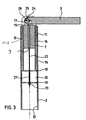
- Fig. 3 can take the part 7 - apart from the molded end shields 8 - about the shape of a sleeve with a relatively thick wall thickness, so that in the center only a small passage 9 with a diameter of, for example. 1 mm to 5 mm, in particular about 2 mm to 4 mm, remains.
- the part 7 has approximately the shape of a cork for closing the tube 2; but its outer diameter is smaller than the inner diameter of the tube 2, and it is housed in a relatively thin-walled sleeve 10, whose Inner diameter is adapted to the outer diameter of the part 7, for example. In the manner of a press or transition fit.
- the sleeve 10 has a wall thickness of, for example, 0.5 mm to 2.5 mm, in particular from 1 mm to 2 mm, and it is longer than the part 7, for example. About twice as long or even longer.
- the outer diameter of the thin-walled sleeve 10 is smaller than the inner diameter of the tube 2, so that they can slide into each other without friction.
- the sleeve 10 at the upper end of the tube 2 is rotatably and slidably guided by a guide sleeve eleventh
- the outer diameter of this guide sleeve 11 is adapted to the inner diameter of the tube 2, while its inner diameter is adapted to the outer diameter of the thin-walled sleeve 10, each preferably approximately in the manner of a loose or transition fit.
- the guide sleeve 11 is positively fixed within the tube 2, for example.
- an upper side radially outwardly projecting edge or collar 12 which rests on the end face of the tube 2, and / or by radially outwardly projecting projections 13, which in corresponding recesses or recesses 14 in the shell of the tube 2 can engage.
- the guide sleeve 11 While the guide sleeve 11 is fixed immovably by these projections 13 and / or by their upper-side collar 12 in the tube 2, it forms a kind of slide for the sleeve 10, which allows a relative displacement and / or - rotation, tilting or other tilting, however Not.
- the sleeve 10 is overlapped by a circumferential collar 15 of the part 7 - in the region of the edge between the lateral surface 16 on the one hand and its upper end face 17 - so that they are compared to the part 7 only to the stop on this collar 15th can move.
- a first perforated disc 18 whose base is preferably approximately circular and is penetrated vertically from the longitudinal axis of the tube 2.
- the lower edge of the sleeve 10 is located at the top of the perforated disc 18 and may be connected to that, for example. Glued, soldered or welded; However, this is not mandatory for the function.
- first perforated disc 18 there is a second, preferably approximately congruent to the first perforated disc 19. However, this is not directly to the first perforated disc 19, sundern extends at a distance below the first perforated disc 18, preferably parallel to that. In between there is an annular body 20.
- the annular body 20 has approximately the shape of a straight circular cylinder with mutually parallel and congruent end faces, and is concentric with the cylinder longitudinal axis of a central through-hole 21 passes.
- the annular body 20 is made of an elastic material such as rubber.
- a traction means for example a metal wire 22, extends concentrically within the tube 2 and in the process passes through the passage 9 of the part 7, the upper perforated disc 18, the annular body 20 and the lower perforated disc 19.
- the traction means or the metal wire 22 has a thickening, for example. Od as a result of a local knot or traversed by the traction means or metal wire and fixed to that, for example. Glued bead 23 od. Like.
- the traction element or the metal wire 22 can not slip through them.
- the upper end of the traction means or metal wire 22 is connected to the lever 5 of the handle 3.
- the lever 5 has a short area beyond the axis of rotation 6, so it is virtually designed as a two-armed lever, wherein the actual handle 3 opposite arm 24, however, is very short, approximately comparable to the thickness of the lever 5, measured in one Cross-sectional plane which is penetrated perpendicularly from the axis of rotation 6, in particular with a maximum length approximately between half the thickness of the lever 5 and its single thickness.
- second arm 24 the upper end of the traction means or metal wire 22 is anchored, preferably on one of the longitudinal axis of the handle 3 together with the axis of rotation 6 plane spanned.
- an anchoring bore 25 parallel to the axis of rotation 6 is provided in the second arm 24 of the lever 5, preferably along its median plane.
- This can be Illustrated as a through hole or blind hole. However, it is - approximately along half the width of the handle 3 - connected via a slot 26 with the end face of the second lever arm 24. While the width of the slot just about corresponds to the diameter of the traction means or metal wire, the diameter of the underlying anchoring bore 25 is significantly larger, for example. Twice as large.
- a thickening is also at the upper end of the traction means or metal wire 22 .
- This can - as well as at the lower end of the traction means or metal wire 22 -.
- the diameter of the thickening is greater than the width of the slot 26, but smaller than the diameter of the anchoring bore 25 in the second arm 24 of the lever fifth Therefore, the thickening of an opening of the anchoring bore 25 can be pushed into the same, so that in this case the traction means or the metal wire 22 itself passes through the slot 26.
- the thickening may be fixed within the anchoring bore 25, for example with adhesive. Possibly. but could also (possibly thickened) end of the traction means or metal wire 22 by a plastic injection molded lever assembly 5,24 encapsulated and thereby be inextricably linked to that.
- the anchoring bore is approximately on the longitudinal axis of the tube 2 not far from the upper-side mouth.
- the length of the traction means or metal wire 22 is dimensioned such that it can extend without tension from the handle 3 to the lower perforated plate 19 in this state.
- the clamping device 4 is free of forces in this state, and thereby takes the elastic, annular body 20 to its original shape, with its outer diameter is slightly smaller than the inner diameter of the tube 2. Therefore, this can be easily displaced within the tube 2, on and from, wherein the height position of the handle 3 is adjustable, as well as be rotated to the left and right, wherein the rotational position of the handle 3 relative to the tube 2 is adjustable.
- this distance is now smaller than the height of the elastic, annular body 20.
- This is therefore in the axial direction, i. in a direction parallel to the longitudinal axis of the tube 2, compressed. He tries to avoid this deformation by the fact that it expands simultaneously in the radial direction, in particular radially outward. But since its original outer diameter is only slightly smaller than the inner diameter of the tube 2, it comes into contact with the inner side 27 of the tube 2. Since the tube is preferably made of a rigid material, for example. Metal, this does not give way, but resisted This is thus the fixed pressure and thus frictionally pressed against the inside 27 of the tube 2 and thereby locked so to speak immovably.
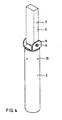
- Fig. 6 is a modified, not claimed embodiment of the invention reproduced here.
- this differs from the embodiment described above only in that the two bearing plates or shields 8 are extended within its plane in one direction, respectively in the same direction transverse to the longitudinal axis of the tube 2.
- These two plates run approximately parallel to each other, with approximately constant distance, and they are in the region of its lower edge, so about (axial) height of the upper end side of the body 7, through a central web connected. This results in a total of approximately the shape of a lateral projection 29 with an approximately U-shaped cross-section.
- the cross section of the trough within this approach 29 corresponds approximately to the cross section of the lever 5 or is slightly larger than that, so that the lever 5 when swiveling down can easily dip into the trough of the projection 29, as in Fig. 6 you can see.
- the outer shape of the projection 29 may be ergonomically designed, for example. By means of recessed grips od. Like.
- a flexible traction means or metal wire 22 may also be a rod or even a tube are used or a possibly bent wire, but also a chain od. Like.
- an axial pressure is exerted on the annular body 20 in the clamping state, with two of these body (s) 20 engaging over or under each other, for example (hole) plates or (hole) disks 18, 19 , are approximated to each other.
- This condition should be absent at the outside Forces to be stable. This can be effected, for example, by inhibiting frictional forces in a bearing part 6, 8 or by a geometric arrangement, for example in the manner of a toggle lever whose end positions are stable, or else by a latching, for example between the lever 3 'and the same Extension 29.
Landscapes
- Engineering & Computer Science (AREA)
- Mechanical Engineering (AREA)
- General Engineering & Computer Science (AREA)
- Chemical & Material Sciences (AREA)
- Public Health (AREA)
- Combustion & Propulsion (AREA)
- Transportation (AREA)
- Health & Medical Sciences (AREA)
- Carriages For Children, Sleds, And Other Hand-Operated Vehicles (AREA)
- Footwear And Its Accessory, Manufacturing Method And Apparatuses (AREA)
- Handcart (AREA)
- Walking Sticks, Umbrellas, And Fans (AREA)
- Mutual Connection Of Rods And Tubes (AREA)
- Exhaust-Gas Circulating Devices (AREA)
Claims (15)
- Poussette ou poussette canne pour enfants avec un châssis, plusieurs roues, une superstructure et au moins une poignée réglable en hauteur et/ou orientable (3), où la/les poignée(s) (3) est/sont couplée(s) ou reliée(s) à au moins un élément élastique s'enfonçant dans (respectivement) un tube (2) du châssis, lequel est réalisé sous forme de corps annulaire, doublement connexe, qui est interpénétré par une encoche traversante centrale et dont la section dans une première phase est (légèrement) inférieure à la section intérieure du tube (2), et dans une deuxième phase peut au moins partiellement être soumise à une pression ou à un écartement vers l'extérieur pour être serrée à l'intérieur du tube (2), caractérisée en ce que le corps élastique présente deux parties frontales parallèles l'une par rapport à l'autre et identiques et qu'il est placé entre un disque perforé supérieur (18) et un disque perforé inférieur (19), respectivement en un matériau rigide, dont l'écartement en sens axial est réglable pour exercer une pression axiale sur les parties frontales du corps élastique placé entre ces parties et pour comprimer ce dernier dans le sens axial, ce dernier évitant l'écrasement axial suite à ses propriétés d'élasticité homogènes par un allongement en sens radial, et où le disque perforé inférieur (19) est couplé à un moyen de tension tandis que le bord inférieur d'un tube ou d'un manchon (10) entourant: le moyen de tension est au niveau de la face supérieure du disque perforé supérieur (18).
- Poussette ou poussette canne pour enfants avec un châssis, plusieurs roues, une superstructure et au moins une poignée réglable en hauteur et/ou orientable (3), où la/les poignée(s) (3) est/sont couplée(s) ou reliée(s) à au moins un élément élastique s'enfonçant dans (respectivement) un tube (2) du châssis, lequel est réalisé sous forme de corps annulaire, doublement connexe, qui est interpénétré par une encoche traversante centrale et dont la section dans une première phase est (légèrement) inférieure à la section intérieure du tube (2), et dans une deuxième phase peut au moins partiellement être soumise à une pression ou à un écartement vers l'extérieur pour être serrée à l'intérieur du tube (2), caractérisée en ce que le corps élastique présente approximativement la forme d'un cylindre circulaire droit avec deux parties frontales parallèles l'une par rapport à l'autre et identiques ainsi qu'une encoche traversante (21) concentrique par rapport à l'axe longitudinal du cylindre, et qu'il est placé entre un disque perforé supérieur (18) et un disque perforé inférieur (19), respectivement en un matériau rigide, dont l'écartement en sens axial est réglable pour exercer une pression axiale sur les parties frontales du corps élastique placé entre ces parties et pour comprimer ce dernier dans le sens axial, ce dernier évitant l'écrasement axial par un allongement en sens radial, et où le disque perforé inférieur (19) est couplé à un moyen de tension tandis que le bord inférieur d'un tube ou d'un manchon (10) entourant le moyen de tension, lequel relie le disque perforé en question (18) à l'unité poignée, est au niveau de la face supérieure du disque perforé supérieur (18).
- Poussette ou poussette canne pour enfants selon l'une des revendications précédentes, caractérisée en ce que l'un des deux éléments réglables l'un par rapport à l'autre est réalisé sous forme de tige, tube, fil (22) ou moyen de tension et que l'autre élément est réalisé sous forme de tube, manchon (10) ou sim. entourant la tige, le tube, le fil (22) ou le moyen de tension ou est équipé de tels éléments, où de préférence la tige, le tube, le fil (22) ou le moyen de tension traverse l'anneau/les anneaux élastique(s).
- Poussette ou poussette canne pour enfants selon la revendication 3, caractérisée en ce que la tige, le tube, le fil (22) ou le moyen de tension s'étend transversalement au-delà, c.-à-d. en dessous de l'anneau/des anneaux élastique(s), par exemple à travers le disque perforé (19) qui y est fixé.
- Poussette ou poussette canne pour enfants selon l'une des revendications 3 ou 4, caractérisée en ce que la tige, le tube, le fil (22) ou le moyen de tension présente une section différente de la forme circulaire, par exemple une section elliptique, allongée, en forme de croix ou d'étoile.
- Poussette ou poussette canne pour enfants selon l'une des revendications précédentes, caractérisée en ce qu'une tige, un tube, un fil (22) ou un moyen de tension peut être déplacé par rapport au tube, manchon (10) ou sim. entourant ce dernier/cette dernière dans le sens axial du tube (2).
- Poussette ou poussette canne pour enfants selon l'une des revendications précédentes, caractérisée en ce qu'au niveau de l'extrémité supérieure d'une tige, d'un tube, d'un fil (22) ou d'un moyen de tension et/ou d'un tube, manchon (10) ou sim. entourant ce dernier/cette dernière est placé un levier (5), de préférence articulé ou moulé.
- Poussette ou poussette canne pour enfants selon la revendication 7, caractérisée en ce que l'axe de pivotement (6) du levier (5) est positionné transversalement par rapport à l'axe longitudinal du tube (2).
- Poussette ou poussette canne pour enfants selon la revendication 7 ou 8, caractérisée en ce qu'au moins un levier (5) présente au niveau de son articulation (6) un deuxième bras de levier de préférence plus court (24), avec une section d'enveloppe entourant tout au moins zone par zone l'axe de pivotement (6) dans son sens longitudinal.
- Poussette ou poussette canne pour enfants selon la revendication 9, caractérisée en ce qu'au niveau du deuxième bras de levier (24) est fixé la tige, le tube, le fil (22) ou tout (autre) moyen de tension, lequel s'étend dans le tube (2) et est couplé avec l'élément pouvant être soumis à une pression ou à un écartement (20) par le biais du disque perforé (19).
- Poussette ou poussette canne pour enfants selon l'une des revendications précédentes, caractérisée en ce qu'au moins un levier (5) présente au niveau de son extrémité articulée une section d'enveloppe (24) entourant tout au moins zone par zone l'axe de pivotement (6) dans son sens longitudinal.
- Poussette ou poussette canne pour enfants selon la revendication 11, caractérisée en ce que la section d'enveloppe (24) est excentrique par rapport à l'axe de pivotement (6) en question, de sorte que l'écartement de sa circonférence varie de l'axe de pivotement en forme de came dans le sens circonférentiel.
- Poussette ou poussette canne pour enfants selon la revendication 12, caractérisée en ce que la section circonférentielle en forme de came s'appuie sur une partie frontale du manchon ou sim.
- Poussette ou poussette canne pour enfants selon l'une des revendications 12 ou 13, caractérisée en ce que la came est disposée de telle façon qu'elle repousse en exerçant une pression sur les deux leviers l'axe de pivotement et la tige qui y est couplée dans le sens axial du manchon ou sim.
- Poussette ou poussette canne pour enfants selon l'une des revendications précédentes, caractérisée en ce qu'à l'extrémité supérieure du tube (2) est prévu un capot d'extrémité ou une manchette de guidage (11) qui sert au guidage du manchon (10) dans le tube (2).
Applications Claiming Priority (2)
| Application Number | Priority Date | Filing Date | Title |
|---|---|---|---|
| DE102007035758 | 2007-07-27 | ||
| PCT/EP2008/006121 WO2009015827A2 (fr) | 2007-07-27 | 2008-07-25 | Poussette pourvue d'au moins une poignée réglable |
Publications (2)
| Publication Number | Publication Date |
|---|---|
| EP2183146A2 EP2183146A2 (fr) | 2010-05-12 |
| EP2183146B1 true EP2183146B1 (fr) | 2010-12-01 |
Family
ID=40030343
Family Applications (1)
| Application Number | Title | Priority Date | Filing Date |
|---|---|---|---|
| EP08785074A Not-in-force EP2183146B1 (fr) | 2007-07-27 | 2008-07-25 | Poussette pourvue d'au moins une poignée réglable |
Country Status (7)
| Country | Link |
|---|---|
| US (1) | US8342564B2 (fr) |
| EP (1) | EP2183146B1 (fr) |
| AT (1) | ATE490147T1 (fr) |
| AU (1) | AU2008280999B2 (fr) |
| DE (1) | DE502008001963D1 (fr) |
| ES (1) | ES2357523T3 (fr) |
| WO (1) | WO2009015827A2 (fr) |
Cited By (1)
| Publication number | Priority date | Publication date | Assignee | Title |
|---|---|---|---|---|
| DE202011109026U1 (de) | 2011-12-14 | 2012-02-28 | Endepro Gmbh | Vorrichtung zum Arretieren einer Schwenkposition |
Families Citing this family (8)
| Publication number | Priority date | Publication date | Assignee | Title |
|---|---|---|---|---|
| US8534683B2 (en) * | 2011-01-10 | 2013-09-17 | Brookefield Hunter, Inc. | Wheelchair handlebar adjustment |
| US20130234418A1 (en) * | 2012-03-08 | 2013-09-12 | Sun Mountain Sports, Inc. | Collapsible golf bag cart with improved folding mechanism |
| WO2017013009A1 (fr) * | 2015-07-17 | 2017-01-26 | Jöran Lundh | Poignée de poussette |
| DE102016109755A1 (de) * | 2016-05-26 | 2017-11-30 | Otto Bock Mobility Solutions Gmbh | Mobilitätshilfe |
| US10654507B2 (en) | 2017-07-12 | 2020-05-19 | Staphen Dewitt Holdings Llc | Apparatus for setting a push-from-behind transportation device by pulling in a leading or abreast position |
| USD844928S1 (en) * | 2017-07-25 | 2019-04-02 | Cambro Manufacturing Company | Dish caddy adjusting lever |
| USD966156S1 (en) | 2020-03-31 | 2022-10-11 | Stahpen Dewilt Holdings LLC | Steering device |
| US11820418B1 (en) | 2021-06-05 | 2023-11-21 | Curious Innovations, LLC | Stroller handles |
Family Cites Families (9)
| Publication number | Priority date | Publication date | Assignee | Title |
|---|---|---|---|---|
| BE528038A (fr) * | ||||
| US6168174B1 (en) * | 1997-12-16 | 2001-01-02 | Alexander Stewart MacDougall | Golf bag push cart |
| DE29811026U1 (de) * | 1998-06-22 | 1998-09-03 | MECHANIK-Langewiesen e.G., 98704 Langewiesen | Verbindungssystem für Rohre |
| GB2351762A (en) * | 1999-07-13 | 2001-01-10 | Link Treasure Ltd | Adjustable tubular frame structure |
| US7188858B2 (en) * | 2002-04-24 | 2007-03-13 | Graco Children's Products Inc. | Foldable stroller |
| US6991248B2 (en) * | 2003-05-05 | 2006-01-31 | Dynamic Brands, Llc | Folding baby stroller system and method |
| US7632035B2 (en) * | 2004-04-30 | 2009-12-15 | Dynamic Brands, Llc | Folding baby stroller |
| US7465306B2 (en) * | 2004-08-13 | 2008-12-16 | Warsaw Orthopedic, Inc. | System and method for positioning a connecting member adjacent the spinal column in minimally invasive procedures |
| JP4811945B2 (ja) * | 2004-11-29 | 2011-11-09 | 株式会社カネカ | 薄膜光電変換装置 |
-
2008
- 2008-07-25 AT AT08785074T patent/ATE490147T1/de active
- 2008-07-25 WO PCT/EP2008/006121 patent/WO2009015827A2/fr not_active Ceased
- 2008-07-25 US US12/452,884 patent/US8342564B2/en not_active Expired - Fee Related
- 2008-07-25 DE DE502008001963T patent/DE502008001963D1/de active Active
- 2008-07-25 ES ES08785074T patent/ES2357523T3/es active Active
- 2008-07-25 AU AU2008280999A patent/AU2008280999B2/en not_active Ceased
- 2008-07-25 EP EP08785074A patent/EP2183146B1/fr not_active Not-in-force
Cited By (2)
| Publication number | Priority date | Publication date | Assignee | Title |
|---|---|---|---|---|
| DE202011109026U1 (de) | 2011-12-14 | 2012-02-28 | Endepro Gmbh | Vorrichtung zum Arretieren einer Schwenkposition |
| WO2013088228A1 (fr) | 2011-12-14 | 2013-06-20 | Endepro Gmbh | Dispositif de blocage d'une position de pivotement |
Also Published As
| Publication number | Publication date |
|---|---|
| ATE490147T1 (de) | 2010-12-15 |
| US8342564B2 (en) | 2013-01-01 |
| US20100207339A1 (en) | 2010-08-19 |
| WO2009015827A3 (fr) | 2009-06-04 |
| AU2008280999A1 (en) | 2009-02-05 |
| ES2357523T3 (es) | 2011-04-27 |
| DE502008001963D1 (de) | 2011-01-13 |
| EP2183146A2 (fr) | 2010-05-12 |
| WO2009015827A2 (fr) | 2009-02-05 |
| AU2008280999B2 (en) | 2012-03-29 |
Similar Documents
| Publication | Publication Date | Title |
|---|---|---|
| EP2183146A2 (fr) | Poussette pourvue d'au moins une poignée réglable | |
| DE10116821B4 (de) | Verstellbare Armlehnenanordnung mit einem einzigen Verstellhebel | |
| DE102008037285B4 (de) | Tisch mit einer schwenkbaren Tischplatte | |
| EP2910146B1 (fr) | Châssis de meuble, notamment châssis de chaise ou de table, et chaise ou table dotée d'un tel châssis de meuble | |
| EP3484719B1 (fr) | Galet de direction muni d'une roue directrice | |
| DE102005005089A1 (de) | Tragelement für ein Sitzmöbel | |
| EP3157388B1 (fr) | Siège pivotant | |
| DE3042604A1 (de) | Gefederter fahrersitz mit einem scherengestell | |
| EP1155643B1 (fr) | Dispositif de support | |
| EP2679115B1 (fr) | Meuble destiné à s'y asseoir | |
| DE202015101436U1 (de) | Höheneinrichtbares Seitenteil für ein Pflegebett | |
| EP1890908B1 (fr) | Systeme de reglage manuel conçu pour un appui lombaire d'un siege de vehicule | |
| DE10254030B4 (de) | Deichsel für Handgabelhubwagen | |
| EP1874160B1 (fr) | Siege, notamment chaise de bureau | |
| EP2581536B1 (fr) | Palier d'angle | |
| EP2450213B1 (fr) | Dispositif de soulèvement et d'abaissement d'un toit de camion soutenu par montants télescopables | |
| DE20005850U1 (de) | Mit mindestens einem Stützteil versehenes Sitzmöbel | |
| DE202016107045U1 (de) | Sitzmöbel | |
| EP2186445B1 (fr) | Sommier pour lit | |
| EP2145568A1 (fr) | Support pour l'extrémité de latte d'un cadre a lattes | |
| DE2543735C2 (de) | Feststell- und bremsbare Lenkrolle | |
| DE29917170U1 (de) | Lattenrost für Betten, Liegen o.dgl. | |
| DE2239339A1 (de) | Anordnung zum bremsen und/oder zum richtungsstellen von rollen und raedern | |
| DE2822981C2 (de) | Krankenhaus-Kinderbett | |
| DE102014110640B4 (de) | Drehverstellbarer Teleskopgriff eines Rollkoffers |
Legal Events
| Date | Code | Title | Description |
|---|---|---|---|
| PUAI | Public reference made under article 153(3) epc to a published international application that has entered the european phase |
Free format text: ORIGINAL CODE: 0009012 |
|
| 17P | Request for examination filed |
Effective date: 20100218 |
|
| AK | Designated contracting states |
Kind code of ref document: A2 Designated state(s): AT BE BG CH CY CZ DE DK EE ES FI FR GB GR HR HU IE IS IT LI LT LU LV MC MT NL NO PL PT RO SE SI SK TR |
|
| AX | Request for extension of the european patent |
Extension state: AL BA MK RS |
|
| GRAP | Despatch of communication of intention to grant a patent |
Free format text: ORIGINAL CODE: EPIDOSNIGR1 |
|
| GRAS | Grant fee paid |
Free format text: ORIGINAL CODE: EPIDOSNIGR3 |
|
| GRAA | (expected) grant |
Free format text: ORIGINAL CODE: 0009210 |
|
| AK | Designated contracting states |
Kind code of ref document: B1 Designated state(s): AT BE BG CH CY CZ DE DK EE ES FI FR GB GR HR HU IE IS IT LI LT LU LV MC MT NL NO PL PT RO SE SI SK TR |
|
| REG | Reference to a national code |
Ref country code: GB Ref legal event code: FG4D Free format text: NOT ENGLISH |
|
| REG | Reference to a national code |
Ref country code: CH Ref legal event code: EP |
|
| REG | Reference to a national code |
Ref country code: IE Ref legal event code: FG4D |
|
| REF | Corresponds to: |
Ref document number: 502008001963 Country of ref document: DE Date of ref document: 20110113 Kind code of ref document: P |
|
| REG | Reference to a national code |
Ref country code: NL Ref legal event code: T3 |
|
| REG | Reference to a national code |
Ref country code: CH Ref legal event code: NV Representative=s name: ISLER & PEDRAZZINI AG |
|
| REG | Reference to a national code |
Ref country code: ES Ref legal event code: FG2A Ref document number: 2357523 Country of ref document: ES Kind code of ref document: T3 Effective date: 20110427 |
|
| PG25 | Lapsed in a contracting state [announced via postgrant information from national office to epo] |
Ref country code: NO Free format text: LAPSE BECAUSE OF FAILURE TO SUBMIT A TRANSLATION OF THE DESCRIPTION OR TO PAY THE FEE WITHIN THE PRESCRIBED TIME-LIMIT Effective date: 20110301 Ref country code: LT Free format text: LAPSE BECAUSE OF FAILURE TO SUBMIT A TRANSLATION OF THE DESCRIPTION OR TO PAY THE FEE WITHIN THE PRESCRIBED TIME-LIMIT Effective date: 20101201 |
|
| LTIE | Lt: invalidation of european patent or patent extension |
Effective date: 20101201 |
|
| PG25 | Lapsed in a contracting state [announced via postgrant information from national office to epo] |
Ref country code: LV Free format text: LAPSE BECAUSE OF FAILURE TO SUBMIT A TRANSLATION OF THE DESCRIPTION OR TO PAY THE FEE WITHIN THE PRESCRIBED TIME-LIMIT Effective date: 20101201 Ref country code: CY Free format text: LAPSE BECAUSE OF FAILURE TO SUBMIT A TRANSLATION OF THE DESCRIPTION OR TO PAY THE FEE WITHIN THE PRESCRIBED TIME-LIMIT Effective date: 20101201 Ref country code: BG Free format text: LAPSE BECAUSE OF FAILURE TO SUBMIT A TRANSLATION OF THE DESCRIPTION OR TO PAY THE FEE WITHIN THE PRESCRIBED TIME-LIMIT Effective date: 20110301 Ref country code: HR Free format text: LAPSE BECAUSE OF FAILURE TO SUBMIT A TRANSLATION OF THE DESCRIPTION OR TO PAY THE FEE WITHIN THE PRESCRIBED TIME-LIMIT Effective date: 20101201 Ref country code: FI Free format text: LAPSE BECAUSE OF FAILURE TO SUBMIT A TRANSLATION OF THE DESCRIPTION OR TO PAY THE FEE WITHIN THE PRESCRIBED TIME-LIMIT Effective date: 20101201 Ref country code: SI Free format text: LAPSE BECAUSE OF FAILURE TO SUBMIT A TRANSLATION OF THE DESCRIPTION OR TO PAY THE FEE WITHIN THE PRESCRIBED TIME-LIMIT Effective date: 20101201 Ref country code: SE Free format text: LAPSE BECAUSE OF FAILURE TO SUBMIT A TRANSLATION OF THE DESCRIPTION OR TO PAY THE FEE WITHIN THE PRESCRIBED TIME-LIMIT Effective date: 20101201 |
|
| REG | Reference to a national code |
Ref country code: IE Ref legal event code: FD4D |
|
| PG25 | Lapsed in a contracting state [announced via postgrant information from national office to epo] |
Ref country code: GR Free format text: LAPSE BECAUSE OF FAILURE TO SUBMIT A TRANSLATION OF THE DESCRIPTION OR TO PAY THE FEE WITHIN THE PRESCRIBED TIME-LIMIT Effective date: 20110302 |
|
| PG25 | Lapsed in a contracting state [announced via postgrant information from national office to epo] |
Ref country code: IS Free format text: LAPSE BECAUSE OF FAILURE TO SUBMIT A TRANSLATION OF THE DESCRIPTION OR TO PAY THE FEE WITHIN THE PRESCRIBED TIME-LIMIT Effective date: 20110401 Ref country code: EE Free format text: LAPSE BECAUSE OF FAILURE TO SUBMIT A TRANSLATION OF THE DESCRIPTION OR TO PAY THE FEE WITHIN THE PRESCRIBED TIME-LIMIT Effective date: 20101201 Ref country code: PT Free format text: LAPSE BECAUSE OF FAILURE TO SUBMIT A TRANSLATION OF THE DESCRIPTION OR TO PAY THE FEE WITHIN THE PRESCRIBED TIME-LIMIT Effective date: 20110401 Ref country code: CZ Free format text: LAPSE BECAUSE OF FAILURE TO SUBMIT A TRANSLATION OF THE DESCRIPTION OR TO PAY THE FEE WITHIN THE PRESCRIBED TIME-LIMIT Effective date: 20101201 Ref country code: IE Free format text: LAPSE BECAUSE OF FAILURE TO SUBMIT A TRANSLATION OF THE DESCRIPTION OR TO PAY THE FEE WITHIN THE PRESCRIBED TIME-LIMIT Effective date: 20101201 |
|
| PG25 | Lapsed in a contracting state [announced via postgrant information from national office to epo] |
Ref country code: PL Free format text: LAPSE BECAUSE OF FAILURE TO SUBMIT A TRANSLATION OF THE DESCRIPTION OR TO PAY THE FEE WITHIN THE PRESCRIBED TIME-LIMIT Effective date: 20101201 Ref country code: SK Free format text: LAPSE BECAUSE OF FAILURE TO SUBMIT A TRANSLATION OF THE DESCRIPTION OR TO PAY THE FEE WITHIN THE PRESCRIBED TIME-LIMIT Effective date: 20101201 |
|
| PLBE | No opposition filed within time limit |
Free format text: ORIGINAL CODE: 0009261 |
|
| STAA | Information on the status of an ep patent application or granted ep patent |
Free format text: STATUS: NO OPPOSITION FILED WITHIN TIME LIMIT |
|
| PG25 | Lapsed in a contracting state [announced via postgrant information from national office to epo] |
Ref country code: DK Free format text: LAPSE BECAUSE OF FAILURE TO SUBMIT A TRANSLATION OF THE DESCRIPTION OR TO PAY THE FEE WITHIN THE PRESCRIBED TIME-LIMIT Effective date: 20101201 |
|
| 26N | No opposition filed |
Effective date: 20110902 |
|
| REG | Reference to a national code |
Ref country code: DE Ref legal event code: R097 Ref document number: 502008001963 Country of ref document: DE Effective date: 20110902 |
|
| PG25 | Lapsed in a contracting state [announced via postgrant information from national office to epo] |
Ref country code: MT Free format text: LAPSE BECAUSE OF FAILURE TO SUBMIT A TRANSLATION OF THE DESCRIPTION OR TO PAY THE FEE WITHIN THE PRESCRIBED TIME-LIMIT Effective date: 20101201 |
|
| BERE | Be: lapsed |
Owner name: ENDEPRO G.M.B.H. Effective date: 20110731 |
|
| PG25 | Lapsed in a contracting state [announced via postgrant information from national office to epo] |
Ref country code: MC Free format text: LAPSE BECAUSE OF NON-PAYMENT OF DUE FEES Effective date: 20110731 |
|
| PG25 | Lapsed in a contracting state [announced via postgrant information from national office to epo] |
Ref country code: BE Free format text: LAPSE BECAUSE OF NON-PAYMENT OF DUE FEES Effective date: 20110731 |
|
| REG | Reference to a national code |
Ref country code: CH Ref legal event code: PL |
|
| PG25 | Lapsed in a contracting state [announced via postgrant information from national office to epo] |
Ref country code: LI Free format text: LAPSE BECAUSE OF NON-PAYMENT OF DUE FEES Effective date: 20120731 Ref country code: CH Free format text: LAPSE BECAUSE OF NON-PAYMENT OF DUE FEES Effective date: 20120731 |
|
| PG25 | Lapsed in a contracting state [announced via postgrant information from national office to epo] |
Ref country code: LU Free format text: LAPSE BECAUSE OF NON-PAYMENT OF DUE FEES Effective date: 20110725 |
|
| PG25 | Lapsed in a contracting state [announced via postgrant information from national office to epo] |
Ref country code: TR Free format text: LAPSE BECAUSE OF FAILURE TO SUBMIT A TRANSLATION OF THE DESCRIPTION OR TO PAY THE FEE WITHIN THE PRESCRIBED TIME-LIMIT Effective date: 20101201 |
|
| PG25 | Lapsed in a contracting state [announced via postgrant information from national office to epo] |
Ref country code: HU Free format text: LAPSE BECAUSE OF FAILURE TO SUBMIT A TRANSLATION OF THE DESCRIPTION OR TO PAY THE FEE WITHIN THE PRESCRIBED TIME-LIMIT Effective date: 20101201 |
|
| PGFP | Annual fee paid to national office [announced via postgrant information from national office to epo] |
Ref country code: ES Payment date: 20130722 Year of fee payment: 6 Ref country code: AT Payment date: 20130719 Year of fee payment: 6 Ref country code: NL Payment date: 20130719 Year of fee payment: 6 |
|
| PGFP | Annual fee paid to national office [announced via postgrant information from national office to epo] |
Ref country code: GB Payment date: 20130723 Year of fee payment: 6 Ref country code: FR Payment date: 20130719 Year of fee payment: 6 |
|
| PGFP | Annual fee paid to national office [announced via postgrant information from national office to epo] |
Ref country code: IT Payment date: 20130730 Year of fee payment: 6 |
|
| PG25 | Lapsed in a contracting state [announced via postgrant information from national office to epo] |
Ref country code: RO Free format text: LAPSE BECAUSE OF FAILURE TO SUBMIT A TRANSLATION OF THE DESCRIPTION OR TO PAY THE FEE WITHIN THE PRESCRIBED TIME-LIMIT Effective date: 20101201 |
|
| REG | Reference to a national code |
Ref country code: NL Ref legal event code: V1 Effective date: 20150201 |
|
| REG | Reference to a national code |
Ref country code: AT Ref legal event code: MM01 Ref document number: 490147 Country of ref document: AT Kind code of ref document: T Effective date: 20140725 |
|
| GBPC | Gb: european patent ceased through non-payment of renewal fee |
Effective date: 20140725 |
|
| PG25 | Lapsed in a contracting state [announced via postgrant information from national office to epo] |
Ref country code: NL Free format text: LAPSE BECAUSE OF NON-PAYMENT OF DUE FEES Effective date: 20150201 |
|
| REG | Reference to a national code |
Ref country code: FR Ref legal event code: ST Effective date: 20150331 |
|
| PG25 | Lapsed in a contracting state [announced via postgrant information from national office to epo] |
Ref country code: IT Free format text: LAPSE BECAUSE OF NON-PAYMENT OF DUE FEES Effective date: 20140725 |
|
| PG25 | Lapsed in a contracting state [announced via postgrant information from national office to epo] |
Ref country code: GB Free format text: LAPSE BECAUSE OF NON-PAYMENT OF DUE FEES Effective date: 20140725 Ref country code: AT Free format text: LAPSE BECAUSE OF NON-PAYMENT OF DUE FEES Effective date: 20140725 Ref country code: FR Free format text: LAPSE BECAUSE OF NON-PAYMENT OF DUE FEES Effective date: 20140731 |
|
| REG | Reference to a national code |
Ref country code: ES Ref legal event code: FD2A Effective date: 20150930 |
|
| PG25 | Lapsed in a contracting state [announced via postgrant information from national office to epo] |
Ref country code: ES Free format text: LAPSE BECAUSE OF NON-PAYMENT OF DUE FEES Effective date: 20140726 |
|
| PGFP | Annual fee paid to national office [announced via postgrant information from national office to epo] |
Ref country code: DE Payment date: 20150929 Year of fee payment: 8 |
|
| REG | Reference to a national code |
Ref country code: DE Ref legal event code: R119 Ref document number: 502008001963 Country of ref document: DE |
|
| PG25 | Lapsed in a contracting state [announced via postgrant information from national office to epo] |
Ref country code: DE Free format text: LAPSE BECAUSE OF NON-PAYMENT OF DUE FEES Effective date: 20170201 |