EP2183416B1 - Device for the detection of breaking of a fibre web - Google Patents
Device for the detection of breaking of a fibre web Download PDFInfo
- Publication number
- EP2183416B1 EP2183416B1 EP08789664.3A EP08789664A EP2183416B1 EP 2183416 B1 EP2183416 B1 EP 2183416B1 EP 08789664 A EP08789664 A EP 08789664A EP 2183416 B1 EP2183416 B1 EP 2183416B1
- Authority
- EP
- European Patent Office
- Prior art keywords
- web
- detection
- detection element
- area
- previous
- Prior art date
- Legal status (The legal status is an assumption and is not a legal conclusion. Google has not performed a legal analysis and makes no representation as to the accuracy of the status listed.)
- Active
Links
Images


Classifications
-
- D—TEXTILES; PAPER
- D01—NATURAL OR MAN-MADE THREADS OR FIBRES; SPINNING
- D01H—SPINNING OR TWISTING
- D01H13/00—Other common constructional features, details or accessories
- D01H13/14—Warning or safety devices, e.g. automatic fault detectors, stop motions ; Monitoring the entanglement of slivers in drafting arrangements
- D01H13/16—Warning or safety devices, e.g. automatic fault detectors, stop motions ; Monitoring the entanglement of slivers in drafting arrangements responsive to reduction in material tension, failure of supply, or breakage, of material
- D01H13/1616—Warning or safety devices, e.g. automatic fault detectors, stop motions ; Monitoring the entanglement of slivers in drafting arrangements responsive to reduction in material tension, failure of supply, or breakage, of material characterised by the detector
- D01H13/1625—Electro-mechanical actuators
-
- D—TEXTILES; PAPER
- D01—NATURAL OR MAN-MADE THREADS OR FIBRES; SPINNING
- D01G—PRELIMINARY TREATMENT OF FIBRES, e.g. FOR SPINNING
- D01G31/00—Warning or safety devices, e.g. automatic fault detectors, stop motions
-
- D—TEXTILES; PAPER
- D01—NATURAL OR MAN-MADE THREADS OR FIBRES; SPINNING
- D01H—SPINNING OR TWISTING
- D01H13/00—Other common constructional features, details or accessories
- D01H13/14—Warning or safety devices, e.g. automatic fault detectors, stop motions ; Monitoring the entanglement of slivers in drafting arrangements
- D01H13/16—Warning or safety devices, e.g. automatic fault detectors, stop motions ; Monitoring the entanglement of slivers in drafting arrangements responsive to reduction in material tension, failure of supply, or breakage, of material
- D01H13/18—Warning or safety devices, e.g. automatic fault detectors, stop motions ; Monitoring the entanglement of slivers in drafting arrangements responsive to reduction in material tension, failure of supply, or breakage, of material stopping supply only
- D01H13/186—Warning or safety devices, e.g. automatic fault detectors, stop motions ; Monitoring the entanglement of slivers in drafting arrangements responsive to reduction in material tension, failure of supply, or breakage, of material stopping supply only guiding or drafting cylinders moving by gravity when a yarn breakage occurs
Definitions
- the present invention relates to a device for the detection of breaking of a fibre web, which can be used in machinery used for processing webs.
- the web then undergoes further processing, downline from carding, for example in a draw frame, a lap winder or combing machine, for the main purpose of obtaining a cleaner web with as regular a gauge as possible and well paralleled fibres.
- machine downtime affects both production costs and the quality of the web, especially the repeatability of the desired production features of the web (degree of cleanliness, regularity of the gauge).
- document CH 383228 shows a machine receiving two webs from two cans and a device for the detection of breaking formed by a fixed cylinder and a mobile cylinder, which holds the web against the fixed cylinder by means of a spring.
- the breaking of the web causes contact between the cylinders, closing a circuit which signals the breakage.
- Document DE 1 172 167 shows a detection device formed by a light emitter and a receiver.
- the beam emitted is interrupted by the web when intact.
- the web breaks, the ray of light reaches the receiver, which signals the breaking.
- Document GB 886,525 shows a lever identification device, wherein the yarn, when intact, keeps a hinged lever in a raised position, against gravity. Following breaking of the yarn, the lever rotates, striking against a plate, which blocks the machine.
- Document US 3,330,007 shows a pile-operated detection device, composed of a frame and a lever, separated electrically from the frame when the web is intact. Following breaking of the web, the web continually fed by the rollers upline piles up under the lever, raising it and putting it in contact with the frame. The blocking circuit is thus closed.
- Document JP-59-168138 shows a detection device comprising optic fibres and a receiver. When the yarn breaks, the beam of light emitted by the fibres is collected by the receiver, which sends a blocking signal.
- a further known detection device comprises a plurality of small, freely moving rollers lying on the web, supported by rotating cylinders placed below the web. When one of the webs breaks, the relative roller falls onto the cylinder below it, closing the blocking circuit.
- the aim of the present invention is to create a detection device which overcomes the drawbacks spoken of with reference to the known art, at the same time satisfying the aforesaid requirements.
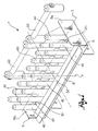
- reference numeral 1 globally denotes a device for the detection of breaking of a fibre web according to the present invention.
- the detection device 1 comprises a frame 2, to which the components of the device are connected, which can be joined to a machine for mounting the said device to the machine.
- the frame 2 comprises a flat bottom wall 4, a side wall 6, joined to the bottom wall 4 and jutting out from it, for example perpendicularly, and an exit wall 8, joined to the lateral wall and inclined so as to be practically parallel to the bottom wall.
- the frame 2 comprises in addition lateral ends 9a, 9b which define the device transversally.
- the device 1 has an entrance area 10, where the web goes into after coming out of processing by other devices or machinery upline of the detection device, for example from a carding machine.
- the device has an exit area 12, where the web comes out of before being directed towards further processing, performed by further devices or machines downline of the detection device 1, for example to the draft unit of a draw frame.
- the web moves along a direction of movement X, in a direction of advancement.
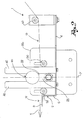
- the device 1 comprises at least one detection element 20, free to move so as to be suitable to move by falling, in a falling direction Y, from an area of normal functioning 22, when the web is intact, to a signalling area 24, when the web incurs a breakage.
- the detection element 20 is supported by the web in transit between the entrance area 10 and the exit area 12, so as to remain in the area of normal functioning 22, above the web itself.
- the detection element 20 is of such a weight as to be supported in the normal functioning area 22 solely by the web in transit.
- the detection element 20 in fact, is sufficiently light to be supported by the web itself in transit, without the assistance of rotating rollers below the web itself.
- the detection element 20 is an internally hollow body, for example made from non-conductive material, such as a plastic material.
- the detection element 20 is of a suitable geometric shape to facilitate its rolling over the web in transit.
- the detection element 20 is a body having a circular transversal cross-section.
- the detection element 20 is an essentially spherical body.
- the device 1 comprises means of detection to detect the presence of said detection element 20 in the signalling area 24.
- the means of detection comprise an emitter 30 of a detection signal, such as a beam of light, and a receiver 32.
- the signal emitted by the emitter 30 reaches the receiver 32 undisturbed; when, following breaking of the web, the detection element 20 loses its support and falls into the signalling area 24, this obstructs the passage of the signal from the emitter to the receiver, in that it is made in such a form, size and material as to be opaque to said signal.
- the receiver 32 not receiving any detection signal, emits a blocking signal to stop the machine.
- the means of detection comprise two electrically uncoupled electric elements which, when the detection element falls, become electrically connected, thus closing the blocking circuit.
- the means of detection are positioned at a height such as to be disengaged structurally from the detection element 20 when said detection element is supported by the.intact web.
- the detection element is supported only by the web, without the help of other organs, for example belonging to such means of detection.
- the device 1 comprises, in addition, means of positioning to limit the movement of the detection element between the entrance area 10 and the exit area 12.
- the means of positioning limit the movement of the detection element in the direction of movement X of the web.
- Said means of positioning comprise a number of rods 40, 140 extending mainly along the falling direction Y of the detection element 20, arranged so as to form a cage for the detection elements.
- the area of normal functioning 22 and the signalling area 24 are defined between said rods 40, 140 in the direction of falling Y.
- said means of positioning limit the movement of the detection element 20 in the transversal direction T.
- Said rods 40, 140 are spaced along the transversal direction T.
- said rods 40, 140 are sized and spaced so as to prevent the passage of the detection element 20 between them, and also, preferably, to prevent contact between one detection element and the one transversally alongside it.
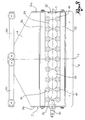
- the means of positioning comprise two rows of rods 40 spaced along the direction of movement X of the web, wherein each row has rods spaced out in the transversal direction T ( figures 1 to 3 ).
- Each detection element 20 is limited in its movement by four rods 40, moving inside the cage formed by these.
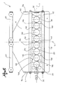
- the means of positioning comprise shaped rods 140 which have at least one concave side 142 such as to accommodate the detection element 20 partially to limit its movement ( figures 4 to 6 ).
- the shaped rod 140 has a normal cross-section, obtained with a plane perpendicular to the direction of falling Y of the detection element 20, having a concave indentation on the side of the detection element, forming said concave side 142.
- the shaped rod 140 has at least one rounded head 144, at least above such indentation.
- the shaped rod 140 has a cross-section in the shape of an "8", with two heads 144 at the extremities, joined by a neck 146 thinner than the heads, which makes the concave side 142.
- the shaped heads help the web to slide along and limit the occurrence of undesired winding.
- the device 1 comprises means of cleaning suitable to free the operating area of the detection device from any residues which may have detached from the web while running through.
- the means of cleaning comprise means of suction comprising at least one nozzle 150 connected to a suction device.
- the nozzle 150 is positioned on the bottom 4 of the frame 2 of the device 1, in the transversal band occupied by the rods 40, 140, preferably in line with the optic eye of the detection device.
- the means of cleaning comprise a blowing mechanism suitable to blow away the residues from the operating area of the detection device.
- the device 1 comprises means of guidance suitable to guide the web between the entrance area 10 and the exit area 12.
- the means of guidance comprise a bar upline 50 and a bar downline 52 extending mainly in a transversal direction T, spaced along the direction of movement X.
- the bars 50, 52 are circular cylindrical.
- a plane tangent to the external surface of said bars 50, 52 defines a plane of movement of the web and that the signalling area 24 is defined below the tangent plane, in the direction of falling Y of the detection element 20.
- the means of guidance comprise a diverter bar 60, positioned upline of the upline bar 50, extending mainly in a transversal direction T.
- the bars 50, 52 are attached to the sides 9a, 9b, while the rods 40, 140 are attached to the bottom wall 4.
- the device 1 comprises a number of detection elements 20, positioned alongside each other transversally, each element being destined to be supported by its respective web.
- the detection device according to the present invention makes it possible to overcome the drawbacks of the known state of the art.
- the web does not suffer from false draws caused by heavy organs supported by it or pressed against it.
- the web is, therefore, free to run along.
- the spherical elements have an accentuated propensity to roll freely in that they minimise the points of contact with the surrounding means of positioning.
- the device makes it possible to limit undesired windings of the web.
- the device satisfies the requisites highlighted previously, in that it detects breaking only when this actually happens, in that the fluctuations of the web in transit do not influence the means of detection.
Landscapes
- Engineering & Computer Science (AREA)
- Textile Engineering (AREA)
- Mechanical Engineering (AREA)
- Treatment Of Fiber Materials (AREA)
- Preliminary Treatment Of Fibers (AREA)
- Spinning Or Twisting Of Yarns (AREA)
Applications Claiming Priority (2)
| Application Number | Priority Date | Filing Date | Title |
|---|---|---|---|
| ITBS20070131 ITBS20070131A1 (it) | 2007-09-03 | 2007-09-03 | Dispositivo di rilevazione della rottura di un nastro di fibra |
| PCT/IB2008/053532 WO2009031090A1 (en) | 2007-09-03 | 2008-09-01 | Device for the detection of breaking of a fibre web |
Publications (2)
| Publication Number | Publication Date |
|---|---|
| EP2183416A1 EP2183416A1 (en) | 2010-05-12 |
| EP2183416B1 true EP2183416B1 (en) | 2014-03-26 |
Family
ID=40174790
Family Applications (1)
| Application Number | Title | Priority Date | Filing Date |
|---|---|---|---|
| EP08789664.3A Active EP2183416B1 (en) | 2007-09-03 | 2008-09-01 | Device for the detection of breaking of a fibre web |
Country Status (5)
| Country | Link |
|---|---|
| EP (1) | EP2183416B1 (it) |
| CN (1) | CN101827963B (it) |
| BR (1) | BRPI0816300B1 (it) |
| IT (1) | ITBS20070131A1 (it) |
| WO (1) | WO2009031090A1 (it) |
Citations (1)
| Publication number | Priority date | Publication date | Assignee | Title |
|---|---|---|---|---|
| JPS49127507U (it) * | 1973-02-28 | 1974-11-01 |
Family Cites Families (9)
| Publication number | Priority date | Publication date | Assignee | Title |
|---|---|---|---|---|
| US1589648A (en) * | 1923-05-19 | 1926-06-22 | Charles W Hubbard | Stop motion |
| FR1288818A (fr) * | 1961-02-14 | 1962-03-30 | Alsacienne Constr Meca | Casse-mèche de machine textile |
| CH478264A (de) * | 1966-08-09 | 1969-09-15 | Luwa Ag | Verfahren zur Überwachung des Luntenlaufes an Flügelspinnmaschinen |
| ES168927Y (es) * | 1971-05-14 | 1972-05-01 | Riera Masot | Dispositivo para-mechas. |
| US4095062A (en) * | 1976-09-03 | 1978-06-13 | Platt Saco Lowell Limited | Stop-motion apparatus |
| CN2043976U (zh) * | 1988-09-10 | 1989-09-06 | 史品山 | 红外式数字显示断纱(线)自动控制器 |
| US5429157A (en) * | 1993-09-07 | 1995-07-04 | Plemons; G. Dale | Blade type drop wire |
| CN2405215Y (zh) * | 2000-02-03 | 2000-11-08 | 山西经纬合力机械制造公司总厂 | 用于一种精梳机的光电检测装置 |
| CN2851299Y (zh) * | 2005-10-20 | 2006-12-27 | 青岛环球集团股份有限公司 | 并条机断条红外线同步监控器 |
-
2007
- 2007-09-03 IT ITBS20070131 patent/ITBS20070131A1/it unknown
-
2008
- 2008-09-01 BR BRPI0816300-6A patent/BRPI0816300B1/pt active IP Right Grant
- 2008-09-01 CN CN2008801054088A patent/CN101827963B/zh active Active
- 2008-09-01 WO PCT/IB2008/053532 patent/WO2009031090A1/en not_active Ceased
- 2008-09-01 EP EP08789664.3A patent/EP2183416B1/en active Active
Patent Citations (1)
| Publication number | Priority date | Publication date | Assignee | Title |
|---|---|---|---|---|
| JPS49127507U (it) * | 1973-02-28 | 1974-11-01 |
Also Published As
| Publication number | Publication date |
|---|---|
| WO2009031090A1 (en) | 2009-03-12 |
| CN101827963B (zh) | 2012-02-15 |
| EP2183416A1 (en) | 2010-05-12 |
| ITBS20070131A1 (it) | 2009-03-04 |
| CN101827963A (zh) | 2010-09-08 |
| BRPI0816300B1 (pt) | 2017-12-12 |
| BRPI0816300A2 (pt) | 2015-11-24 |
Similar Documents
| Publication | Publication Date | Title |
|---|---|---|
| EP2361867B1 (en) | Yarn winding machine | |
| US20050076476A1 (en) | Apparatus at a draw frame for supplying fibre slivers to a drawing mechanism comprising at least two pairs of rollers | |
| JP5368164B2 (ja) | 繊維機械の延伸システム、例えば練篠機、カード機、コーマにおいて少なくとも一つの移動する繊維スライバを監視する監視装置 | |
| US4176514A (en) | Method of controlling the operating conditions of a ring spinning machine and apparatus for implementing the method | |
| US5487208A (en) | Device for the detection of breakage of textile fiber slivers before a draw frame | |
| CN105722775A (zh) | 接收从造纸机中的烘缸到达的纸幅并且将纸幅卷绕成卷的卷纸装置和使用卷纸装置的造纸机 | |
| JPS5828378B2 (ja) | 精紡機におけるドラフト装置への供給ストランドの供給中断装置 | |
| WO2009031090A1 (en) | Device for the detection of breaking of a fibre web | |
| US7650672B2 (en) | Apparatus on a spinning preparation machine for monitoring at least one sliver | |
| CN100542924C (zh) | 用于检测纱线的装置 | |
| US7644474B2 (en) | Apparatus on a spinning preparation machine for monitoring fibre material | |
| GB2358644A (en) | Apparatus for monitoring a textile fibre sliver | |
| US4065831A (en) | Stop motion for drawing frames | |
| US4914785A (en) | Device to feed fiber silvers | |
| JP2015178688A (ja) | 繊維制御部材、ドラフト装置、及び紡績機 | |
| JP2672859B2 (ja) | 個別型断糸処理装置 | |
| US3271823A (en) | Stop motion for textile fiber drafting machine | |
| US4506498A (en) | Textile yarn spinning machine with supply strand interruption | |
| CN104822869A (zh) | 用于监控纬纱的装置和方法 | |
| CN213568904U (zh) | 一种涤棉纱络筒机卷线防断线装置 | |
| US3434274A (en) | Apparatus for winding rovings having anti-tangle plate stop motion device | |
| CA1073075A (en) | Stop-motion apparatus | |
| CN103030031A (zh) | 制造交叉卷绕筒子的纺织机工位的吸嘴的针排 | |
| US3443283A (en) | Fiber condenser with combined stop motion and waste disposal for textile drafting units | |
| US3162004A (en) | Automatic scavenger for paper yarn machine |
Legal Events
| Date | Code | Title | Description |
|---|---|---|---|
| PUAI | Public reference made under article 153(3) epc to a published international application that has entered the european phase |
Free format text: ORIGINAL CODE: 0009012 |
|
| 17P | Request for examination filed |
Effective date: 20100205 |
|
| AK | Designated contracting states |
Kind code of ref document: A1 Designated state(s): AT BE BG CH CY CZ DE DK EE ES FI FR GB GR HR HU IE IS IT LI LT LU LV MC MT NL NO PL PT RO SE SI SK TR |
|
| AX | Request for extension of the european patent |
Extension state: AL BA MK RS |
|
| DAX | Request for extension of the european patent (deleted) | ||
| 17Q | First examination report despatched |
Effective date: 20130311 |
|
| GRAP | Despatch of communication of intention to grant a patent |
Free format text: ORIGINAL CODE: EPIDOSNIGR1 |
|
| INTG | Intention to grant announced |
Effective date: 20131022 |
|
| RIN1 | Information on inventor provided before grant (corrected) |
Inventor name: BRANDOLIN, ANTONELLO |
|
| GRAS | Grant fee paid |
Free format text: ORIGINAL CODE: EPIDOSNIGR3 |
|
| GRAA | (expected) grant |
Free format text: ORIGINAL CODE: 0009210 |
|
| AK | Designated contracting states |
Kind code of ref document: B1 Designated state(s): AT BE BG CH CY CZ DE DK EE ES FI FR GB GR HR HU IE IS IT LI LT LU LV MC MT NL NO PL PT RO SE SI SK TR |
|
| REG | Reference to a national code |
Ref country code: GB Ref legal event code: FG4D |
|
| REG | Reference to a national code |
Ref country code: CH Ref legal event code: EP |
|
| REG | Reference to a national code |
Ref country code: AT Ref legal event code: REF Ref document number: 659062 Country of ref document: AT Kind code of ref document: T Effective date: 20140415 |
|
| REG | Reference to a national code |
Ref country code: IE Ref legal event code: FG4D |
|
| REG | Reference to a national code |
Ref country code: DE Ref legal event code: R096 Ref document number: 602008031142 Country of ref document: DE Effective date: 20140508 |
|
| REG | Reference to a national code |
Ref country code: CH Ref legal event code: PUE Owner name: MARZOLI MACHINES TEXTILES S.R.L, IT Free format text: FORMER OWNER: MARZOLI S.P.A., IT Ref country code: CH Ref legal event code: NV Representative=s name: JACOBACCI AND PARTNERS SA, CH |
|
| RAP2 | Party data changed (patent owner data changed or rights of a patent transferred) |
Owner name: MARZOLI MACHINES TEXTILES S.R.L |
|
| PG25 | Lapsed in a contracting state [announced via postgrant information from national office to epo] |
Ref country code: LT Free format text: LAPSE BECAUSE OF FAILURE TO SUBMIT A TRANSLATION OF THE DESCRIPTION OR TO PAY THE FEE WITHIN THE PRESCRIBED TIME-LIMIT Effective date: 20140326 Ref country code: NO Free format text: LAPSE BECAUSE OF FAILURE TO SUBMIT A TRANSLATION OF THE DESCRIPTION OR TO PAY THE FEE WITHIN THE PRESCRIBED TIME-LIMIT Effective date: 20140626 |
|
| REG | Reference to a national code |
Ref country code: CH Ref legal event code: PK Free format text: BERICHTIGUNG INHABER |
|
| RAP2 | Party data changed (patent owner data changed or rights of a patent transferred) |
Owner name: MARZOLI MACHINES TEXTILE S.R.L. |
|
| REG | Reference to a national code |
Ref country code: AT Ref legal event code: MK05 Ref document number: 659062 Country of ref document: AT Kind code of ref document: T Effective date: 20140326 |
|
| REG | Reference to a national code |
Ref country code: NL Ref legal event code: VDEP Effective date: 20140326 |
|
| REG | Reference to a national code |
Ref country code: LT Ref legal event code: MG4D |
|
| PG25 | Lapsed in a contracting state [announced via postgrant information from national office to epo] |
Ref country code: SE Free format text: LAPSE BECAUSE OF FAILURE TO SUBMIT A TRANSLATION OF THE DESCRIPTION OR TO PAY THE FEE WITHIN THE PRESCRIBED TIME-LIMIT Effective date: 20140326 Ref country code: FI Free format text: LAPSE BECAUSE OF FAILURE TO SUBMIT A TRANSLATION OF THE DESCRIPTION OR TO PAY THE FEE WITHIN THE PRESCRIBED TIME-LIMIT Effective date: 20140326 |
|
| PG25 | Lapsed in a contracting state [announced via postgrant information from national office to epo] |
Ref country code: LV Free format text: LAPSE BECAUSE OF FAILURE TO SUBMIT A TRANSLATION OF THE DESCRIPTION OR TO PAY THE FEE WITHIN THE PRESCRIBED TIME-LIMIT Effective date: 20140326 Ref country code: HR Free format text: LAPSE BECAUSE OF FAILURE TO SUBMIT A TRANSLATION OF THE DESCRIPTION OR TO PAY THE FEE WITHIN THE PRESCRIBED TIME-LIMIT Effective date: 20140326 |
|
| PG25 | Lapsed in a contracting state [announced via postgrant information from national office to epo] |
Ref country code: BG Free format text: LAPSE BECAUSE OF FAILURE TO SUBMIT A TRANSLATION OF THE DESCRIPTION OR TO PAY THE FEE WITHIN THE PRESCRIBED TIME-LIMIT Effective date: 20140626 Ref country code: NL Free format text: LAPSE BECAUSE OF FAILURE TO SUBMIT A TRANSLATION OF THE DESCRIPTION OR TO PAY THE FEE WITHIN THE PRESCRIBED TIME-LIMIT Effective date: 20140326 Ref country code: CY Free format text: LAPSE BECAUSE OF FAILURE TO SUBMIT A TRANSLATION OF THE DESCRIPTION OR TO PAY THE FEE WITHIN THE PRESCRIBED TIME-LIMIT Effective date: 20140326 Ref country code: IS Free format text: LAPSE BECAUSE OF FAILURE TO SUBMIT A TRANSLATION OF THE DESCRIPTION OR TO PAY THE FEE WITHIN THE PRESCRIBED TIME-LIMIT Effective date: 20140726 Ref country code: BE Free format text: LAPSE BECAUSE OF FAILURE TO SUBMIT A TRANSLATION OF THE DESCRIPTION OR TO PAY THE FEE WITHIN THE PRESCRIBED TIME-LIMIT Effective date: 20140326 Ref country code: CZ Free format text: LAPSE BECAUSE OF FAILURE TO SUBMIT A TRANSLATION OF THE DESCRIPTION OR TO PAY THE FEE WITHIN THE PRESCRIBED TIME-LIMIT Effective date: 20140326 Ref country code: EE Free format text: LAPSE BECAUSE OF FAILURE TO SUBMIT A TRANSLATION OF THE DESCRIPTION OR TO PAY THE FEE WITHIN THE PRESCRIBED TIME-LIMIT Effective date: 20140326 Ref country code: RO Free format text: LAPSE BECAUSE OF FAILURE TO SUBMIT A TRANSLATION OF THE DESCRIPTION OR TO PAY THE FEE WITHIN THE PRESCRIBED TIME-LIMIT Effective date: 20140326 |
|
| PG25 | Lapsed in a contracting state [announced via postgrant information from national office to epo] |
Ref country code: SK Free format text: LAPSE BECAUSE OF FAILURE TO SUBMIT A TRANSLATION OF THE DESCRIPTION OR TO PAY THE FEE WITHIN THE PRESCRIBED TIME-LIMIT Effective date: 20140326 Ref country code: PL Free format text: LAPSE BECAUSE OF FAILURE TO SUBMIT A TRANSLATION OF THE DESCRIPTION OR TO PAY THE FEE WITHIN THE PRESCRIBED TIME-LIMIT Effective date: 20140326 Ref country code: AT Free format text: LAPSE BECAUSE OF FAILURE TO SUBMIT A TRANSLATION OF THE DESCRIPTION OR TO PAY THE FEE WITHIN THE PRESCRIBED TIME-LIMIT Effective date: 20140326 Ref country code: ES Free format text: LAPSE BECAUSE OF FAILURE TO SUBMIT A TRANSLATION OF THE DESCRIPTION OR TO PAY THE FEE WITHIN THE PRESCRIBED TIME-LIMIT Effective date: 20140326 |
|
| PG25 | Lapsed in a contracting state [announced via postgrant information from national office to epo] |
Ref country code: PT Free format text: LAPSE BECAUSE OF FAILURE TO SUBMIT A TRANSLATION OF THE DESCRIPTION OR TO PAY THE FEE WITHIN THE PRESCRIBED TIME-LIMIT Effective date: 20140728 |
|
| REG | Reference to a national code |
Ref country code: DE Ref legal event code: R097 Ref document number: 602008031142 Country of ref document: DE |
|
| PG25 | Lapsed in a contracting state [announced via postgrant information from national office to epo] |
Ref country code: DK Free format text: LAPSE BECAUSE OF FAILURE TO SUBMIT A TRANSLATION OF THE DESCRIPTION OR TO PAY THE FEE WITHIN THE PRESCRIBED TIME-LIMIT Effective date: 20140326 |
|
| PLBE | No opposition filed within time limit |
Free format text: ORIGINAL CODE: 0009261 |
|
| STAA | Information on the status of an ep patent application or granted ep patent |
Free format text: STATUS: NO OPPOSITION FILED WITHIN TIME LIMIT |
|
| 26N | No opposition filed |
Effective date: 20150106 |
|
| PG25 | Lapsed in a contracting state [announced via postgrant information from national office to epo] |
Ref country code: IT Free format text: LAPSE BECAUSE OF FAILURE TO SUBMIT A TRANSLATION OF THE DESCRIPTION OR TO PAY THE FEE WITHIN THE PRESCRIBED TIME-LIMIT Effective date: 20140326 |
|
| REG | Reference to a national code |
Ref country code: DE Ref legal event code: R097 Ref document number: 602008031142 Country of ref document: DE Effective date: 20150106 |
|
| PG25 | Lapsed in a contracting state [announced via postgrant information from national office to epo] |
Ref country code: MC Free format text: LAPSE BECAUSE OF FAILURE TO SUBMIT A TRANSLATION OF THE DESCRIPTION OR TO PAY THE FEE WITHIN THE PRESCRIBED TIME-LIMIT Effective date: 20140326 Ref country code: LU Free format text: LAPSE BECAUSE OF FAILURE TO SUBMIT A TRANSLATION OF THE DESCRIPTION OR TO PAY THE FEE WITHIN THE PRESCRIBED TIME-LIMIT Effective date: 20140901 |
|
| GBPC | Gb: european patent ceased through non-payment of renewal fee |
Effective date: 20140901 |
|
| REG | Reference to a national code |
Ref country code: IE Ref legal event code: MM4A |
|
| REG | Reference to a national code |
Ref country code: FR Ref legal event code: ST Effective date: 20150529 |
|
| PG25 | Lapsed in a contracting state [announced via postgrant information from national office to epo] |
Ref country code: SI Free format text: LAPSE BECAUSE OF FAILURE TO SUBMIT A TRANSLATION OF THE DESCRIPTION OR TO PAY THE FEE WITHIN THE PRESCRIBED TIME-LIMIT Effective date: 20140326 Ref country code: GB Free format text: LAPSE BECAUSE OF NON-PAYMENT OF DUE FEES Effective date: 20140901 |
|
| PG25 | Lapsed in a contracting state [announced via postgrant information from national office to epo] |
Ref country code: FR Free format text: LAPSE BECAUSE OF NON-PAYMENT OF DUE FEES Effective date: 20140930 Ref country code: IE Free format text: LAPSE BECAUSE OF NON-PAYMENT OF DUE FEES Effective date: 20140901 |
|
| PG25 | Lapsed in a contracting state [announced via postgrant information from national office to epo] |
Ref country code: GR Free format text: LAPSE BECAUSE OF FAILURE TO SUBMIT A TRANSLATION OF THE DESCRIPTION OR TO PAY THE FEE WITHIN THE PRESCRIBED TIME-LIMIT Effective date: 20140627 Ref country code: MT Free format text: LAPSE BECAUSE OF FAILURE TO SUBMIT A TRANSLATION OF THE DESCRIPTION OR TO PAY THE FEE WITHIN THE PRESCRIBED TIME-LIMIT Effective date: 20140326 |
|
| PG25 | Lapsed in a contracting state [announced via postgrant information from national office to epo] |
Ref country code: HU Free format text: LAPSE BECAUSE OF FAILURE TO SUBMIT A TRANSLATION OF THE DESCRIPTION OR TO PAY THE FEE WITHIN THE PRESCRIBED TIME-LIMIT; INVALID AB INITIO Effective date: 20080901 Ref country code: TR Free format text: LAPSE BECAUSE OF FAILURE TO SUBMIT A TRANSLATION OF THE DESCRIPTION OR TO PAY THE FEE WITHIN THE PRESCRIBED TIME-LIMIT Effective date: 20140326 |
|
| P01 | Opt-out of the competence of the unified patent court (upc) registered |
Effective date: 20230523 |
|
| REG | Reference to a national code |
Ref country code: CH Ref legal event code: U11 Free format text: ST27 STATUS EVENT CODE: U-0-0-U10-U11 (AS PROVIDED BY THE NATIONAL OFFICE) Effective date: 20251001 |
|
| PGFP | Annual fee paid to national office [announced via postgrant information from national office to epo] |
Ref country code: DE Payment date: 20250923 Year of fee payment: 18 |
|
| PGFP | Annual fee paid to national office [announced via postgrant information from national office to epo] |
Ref country code: CH Payment date: 20251001 Year of fee payment: 18 |