EP2183456B1 - Rollladen - Google Patents
Rollladen Download PDFInfo
- Publication number
- EP2183456B1 EP2183456B1 EP08760861.8A EP08760861A EP2183456B1 EP 2183456 B1 EP2183456 B1 EP 2183456B1 EP 08760861 A EP08760861 A EP 08760861A EP 2183456 B1 EP2183456 B1 EP 2183456B1
- Authority
- EP
- European Patent Office
- Prior art keywords
- slats
- roller shutter
- shutter according
- slots
- groove
- Prior art date
- Legal status (The legal status is an assumption and is not a legal conclusion. Google has not performed a legal analysis and makes no representation as to the accuracy of the status listed.)
- Active
Links
Images




Classifications
-
- E—FIXED CONSTRUCTIONS
- E06—DOORS, WINDOWS, SHUTTERS, OR ROLLER BLINDS IN GENERAL; LADDERS
- E06B—FIXED OR MOVABLE CLOSURES FOR OPENINGS IN BUILDINGS, VEHICLES, FENCES OR LIKE ENCLOSURES IN GENERAL, e.g. DOORS, WINDOWS, BLINDS, GATES
- E06B9/00—Screening or protective devices for wall or similar openings, with or without operating or securing mechanisms; Closures of similar construction
- E06B9/02—Shutters, movable grilles, or other safety closing devices, e.g. against burglary
- E06B9/08—Roll-type closures
- E06B9/11—Roller shutters
- E06B9/15—Roller shutters with closing members formed of slats or the like
- E06B2009/1533—Slat connections
- E06B2009/155—Slats connected by separate elements
- E06B2009/1555—Flexible elements, e.g. tapes, strips, cords or chains
Definitions
- the present invention relates to a roller shutter according to the preamble of claim 1 and a method for mounting the slats of the shutter.
- Roller shutters of this kind in particular for mounting on a building opening with a large number of slats coupled to one another, which are preferably movable from a wound-up position into a planar position in front of a building opening, are known per se.
- a roller shutter which has a plurality of lamellae, which have a hook element at its upper edge and a counter hook on its underside.
- the hook is formed from a web on which a plurality of openings are recessed sin. If the slats hang loosely together, the openings are in the visible range and thus allow a light incidence. Above a building opening, the slats can be wound on a roll, being rotatable in the region of the hook and the counter hook.
- the slats When unwinding, the slats are pulled apart by their own weight and a building opening is partially shadowed by the roller shutter, then completely translucent. Then the slats are initially placed in the lower area, up to the top of the building opening on each other, until the building opening is shaded opaque.
- the lamellae which are formed as tubular elements, penetrated by holes through which a wire rope is pulled.
- a sleeve is pulled over the wire rope in each case between two slats.
- tubular elements used are relatively unstable and bend easily.
- the FR 920 097 A revealed in Fig. 6-9 a curtain with individual wooden slats, which are interconnected by means of a cable.
- connecting means perforating connecting elements such as nails, screws or rivets and the like. Used, which are driven by the piercing of the cable into the wood of the slats.
- the DE 204 694 C discloses a tank made of wooden slats, which is interconnected by a flexible band. This carrier tape extends in front of the slats, outside of a slit extending in the longitudinal direction of the slit, which is introduced into the slat.
- roller shutter is to be created, which has the three disadvantages of high assembly costs, adverse optics and no optimal light transmission at the same time minimized as much as possible.
- the invention therefore has the task of creating a roller shutter, in which the individual lamellae are connected to each other by means of at least one flexible tension element and held thereon at a defined distance from each other, the optics of the tension element and the light inlet are as little as possible impaired.
- the roller shutter according to the invention should in particular also be such that the assembly effort for its production can be kept relatively low.
- the individual lamellae are provided with slots preferably oriented transversely to their longitudinal direction.
- the slats are attached to retaining clips, preferably locked.
- FIG. 1 a building opening 1 extending over two floors is shown, which is divided into several surface elements, and can be shaded by blinds 2 according to the invention, wherein the blinds 2 have a multiplicity of lamellae 3.
- the blinds form such wide and narrow translucent surfaces 4, 5.
- the lamellae 3 preferably have - but not necessarily - a cross section according to the type Fig. 2 on.
- the lamellae 3 are preferably made of a light metal such as aluminum and are particularly preferably designed as solid, non-hollow (extruded) profiles.
- the individual lamellae 3 in cross-section preferably only an extension of a few millimeters (5-15 mm) have, so that they remain lightweight despite training as solid sections and yet are particularly stable, so that they have significant advantages over hollow sections form similar low cross-section, which usually bend relatively easily.
- Fig. 2a shows the state of the preferred orientation when the slats 3 are used for shading a vertical surface.
- the use of the slats 3 is of course not limited to this geometry of the slats and the selected orientation. The illustrated geometry is particularly advantageous.
- the lamellae 3 form in cross-section almost a kind of right-angled triangle, wherein the triangle to be considered in section a base 6, here almost at right angles aligned side surface 8 - but preferably curved in itself concave - and an inclined surface 7 has.
- the edge regions between the surfaces 6, 7, 8 are preferably provided with relatively large radii and thus formed rounded.
- the lamellae 3 further preferably have at least one in the longitudinal direction of the lamella (perpendicular to the plane of the Fig. 2a ) extending, undercut groove 9.
- the groove 9 is provided with chamfers 10 and 11, wherein the one of the slopes 10 is preferably stronger (in Fig. 2a to the vertical z) is inclined than the other slope 11th
- the groove 9 is preferably formed in the base or base 6 of the blade 3. But it is also conceivable that they in the side surface 8 ( Fig. 2b ) train.
- slats 3 of the curtain are provided at least one or more locations with slots 13 which are aligned at an angle, preferably perpendicular to the longitudinal direction of the lamellae and thus also to the grooves 9.
- FIG. 3a shows a partial section of a blade 3 in a plan view, so that in particular the slot 13 is clearly visible.
- the at least one slot 13 is preferably introduced in a simple manner by a saw cut transversely to the longitudinal extension of the lamella 3.
- each slot 13 extends completely in the direction of a traction element to be accommodated in it (described below) completely (in FIG Fig. 3a according to a vertical orientation of the tension element from top to bottom) from the side surface 8 forth to in the region of the center of the blade 3 (see also the section of Fig. 5 ), where he the lamella - as in Fig. 5 to recognize also from top to bottom completely interspersed.
- the slot 13 has a depth a and a width b.
- the dimensions of the slot 13 are reflected in another component, as described below.
- Each slot 13 passes through a tension element of the shutter.
- the tension element is designed as a flexible cable 16 - for example as a thin steel cable. It is also conceivable to manufacture the tension element from a thin strip material. The tension element is used to couple the slats 3.
- the tension element must not be threaded through holes of the slats but it can be inserted laterally easy in the slot 13 of the slat or even simultaneously in the slots of a plurality of juxtaposed slats.
- lateral slots 13 in the slats is in particular much easier to implement.
- a plurality of fins are arranged on a corresponding device, which can be slit in a section with a thin circular saw blade. This achieves a high degree of rationalization.
- a plurality of fins can be connected in a single operation by simply inserting the ropes 16 and fixing the ropes in the slots 13.
- the fixing of the ropes 16 in the slat slots can also be done very efficiently in many ways. This includes, for example, the gluing of the tension element (rope) in each slot 13 (FIG. Fig. 3c : Bond 22; Adhesive outlet 23). Preference is given to a lateral pressing (upsetting) of the slot walls with a compression tool 24, which also closes the slot 13 behind the rope again and ensures sufficient attachment ( Fig. 3c third slot from the left).
- the squeezing of the slot can be accomplished for example by a roller 25 with a groove, which is guided in a single operation on a plurality of fins ( Fig. 3c : right slot). By pressing the slat slot this is closed, which improves the appearance of the shutter in the slots 13 in the slats.
- the connecting elements are arranged on the tension elements, which engage in openings of the slats.
- the openings can be used as grooves 9 (FIG. Fig. 6 to 8 ) or as bores 26 (FIG. 26).
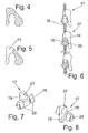
- this connecting element as a clip holder 17 (see Fig. 6 to 8 ), which is mounted on the tension member, for example, by each Klipshalter is molded in its manufacture to the tension element.
- the rope preferably a wound stainless steel wire rope, is overmoulded directly with the plastic clip holders.
- the clip holders thus arranged at a distance from the cable 116 preferably consist of at least two regions: at least one latching region 18 and a covering region 19.
- the latching region 18 is designed to be latched in the groove 9 in the manner of a latching clip. In the latched position, the latching portion 18 engages latching into the profile groove 9 of the slats and the cover region 19 extending substantially perpendicular to the latching region fills the slot 13 of the slats 3 and encases the cable 16.
- the clip holder 17 is made of a plastic.
- the wire rope 16 is thereby encompassed by the clip holders 17, so that the entire covering area is filled with the lamellae 3. As a result, it can not come to a contact corrosion between the stainless steel cable and the preferably made of aluminum slats.
- the locking groove 18 corresponding to the groove 9 has latching arms 20.
- This locking arms 20 hooked form-fitting manner in the groove 9, in particular behind the undercuts 12.
- the angular arrangement of the locking arms is chosen so that the insertion into the groove 9 is very easy and a secure attachment (security against loosening) is given.
- FIG. 7 shows a clip holder 17 according to the invention without wire 16 in an isometric view, from the installation direction on the inclined surface 7 of a blade.
- the latching region 18 with the latching arms 20 arranged symmetrically on both sides is clearly visible.
- FIG. 8 also shows the clip holder 17 according to the invention in an isometric view in the installation direction on the side surface 8 of a blade. Clearly visible is the cover 19, the contour exactly fills the slot 13 of the fins 3 and the surface of the fins is adjusted. As a result, the slot is completely covered and it creates an attractive appearance.
- a through hole 21 which passes through the steel cable 16.
- the shape of the preferred embodiment of the corresponding parts clip holder 17 and fins 3 are not limited to this embodiment.
- the shape of the latching area 18 of the clip holders 17 are adapted to the shape of the groove 9 of the slats 3 and the shape of the covering area 19 matches the shape of the slot 13.
- the encapsulation of the steel cables with the clip holders 17 according to the invention can be done for example in a simple manner in a multiple tool.
- FIG. 9 illustrates a particularly advantageous method for mounting the slats on the traction elements provided with the clip holders.
- the slats 3 are pivoted in a pivoting movement between 2 clip holder 17 after the extrusion of the tension elements with the clip holders in a sufficiently large axial distance on the pull cable 16.
- the bevel 10 has a greater angle ⁇ to the perpendicular bisector of the groove than the slope 11, so that the blade 3 can be easily pivoted between the clip holder 17, even at a very small distance.
- the assembly of the slats 3 on the clip holder 17 and the connection with the cable 16 is accomplished in an automatic, continuous assembly sequence (swing).
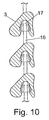
- FIG. 10 shows the final assembly position of the slats 3 on the rope or snapped into the clip holding 17th
- the openings in the slats are formed as holes 26, and the connecting elements, which serve as a holder, are formed by plug 27 here conical shape, which engage here in the corresponding conical openings 26 from below and there are preferably fixed by clamping.
- the plugs can also be made of plastic and attached to the rope 16 be injected.
- the assembly is preferably made possible by a slot 13 in the manner of the other figures, which extends into the opening 26.
Landscapes
- Engineering & Computer Science (AREA)
- Structural Engineering (AREA)
- Architecture (AREA)
- Civil Engineering (AREA)
- Operating, Guiding And Securing Of Roll- Type Closing Members (AREA)
- Connection Of Plates (AREA)
- Roof Covering Using Slabs Or Stiff Sheets (AREA)
Priority Applications (1)
| Application Number | Priority Date | Filing Date | Title |
|---|---|---|---|
| PL08760861T PL2183456T3 (pl) | 2007-08-03 | 2008-06-11 | Żaluzja |
Applications Claiming Priority (2)
| Application Number | Priority Date | Filing Date | Title |
|---|---|---|---|
| DE200710036766 DE102007036766A1 (de) | 2007-08-03 | 2007-08-03 | Rollladen insbesondere zur Montage an einer Gebäudeöffnung |
| PCT/EP2008/057311 WO2009019061A1 (de) | 2007-08-03 | 2008-06-11 | Rollladen |
Publications (2)
| Publication Number | Publication Date |
|---|---|
| EP2183456A1 EP2183456A1 (de) | 2010-05-12 |
| EP2183456B1 true EP2183456B1 (de) | 2016-11-16 |
Family
ID=39637615
Family Applications (1)
| Application Number | Title | Priority Date | Filing Date |
|---|---|---|---|
| EP08760861.8A Active EP2183456B1 (de) | 2007-08-03 | 2008-06-11 | Rollladen |
Country Status (5)
| Country | Link |
|---|---|
| EP (1) | EP2183456B1 (pl) |
| CN (1) | CN101772612B (pl) |
| DE (1) | DE102007036766A1 (pl) |
| PL (1) | PL2183456T3 (pl) |
| WO (1) | WO2009019061A1 (pl) |
Families Citing this family (2)
| Publication number | Priority date | Publication date | Assignee | Title |
|---|---|---|---|---|
| EP2458127A3 (en) * | 2010-11-29 | 2014-07-09 | Helmut KÖSTER | Daylight roller shutter |
| DE102012104174A1 (de) * | 2012-05-14 | 2013-11-14 | Helmut Koester | Fensterbehänge |
Citations (2)
| Publication number | Priority date | Publication date | Assignee | Title |
|---|---|---|---|---|
| DE204694C (de) * | 1906-08-02 | 1908-12-01 | Stahl Sebald | Rolladen mit unverschliessbaren Lichtspalten aus Staeben rautenfoermigen querschnittes, die auf biegsamen, durch Schlitze der Staebe hindurchgehenden Tragbaendern gegeneinander unverschlieblich befestigt sind. |
| DE10139583A1 (de) * | 2001-12-12 | 2003-02-27 | Ulrich Clauss | Flächengebilde |
Family Cites Families (9)
| Publication number | Priority date | Publication date | Assignee | Title |
|---|---|---|---|---|
| CH12614A (de) * | 1896-06-18 | 1897-01-31 | George Bendix | Rolladen mit Drahtseilbefestigung der einzelnen Stäbe |
| FR920097A (fr) * | 1945-07-13 | 1947-03-26 | Procédé de fabrication des rideaux en bois | |
| FR970822A (fr) * | 1948-04-26 | 1951-01-09 | Rideau roulant en bois, ou en matière moulée, monté et articulé avec câbles acier tressé, genre rideaux à coulisse | |
| GB900828A (en) * | 1958-10-24 | 1962-07-11 | Griesser Ag | Improvements in or relating to roller-shutters |
| FR1519724A (fr) | 1967-02-20 | 1968-04-05 | Manuf De Stores Roulants Gries | Volet enroulable à lames en métal pouvant être assemblées par enfilage dans la direction de leur longueur |
| CN2213828Y (zh) * | 1994-08-11 | 1995-11-29 | 周建刚 | 多功能异型百叶窗帘 |
| CN2371324Y (zh) * | 1999-04-08 | 2000-03-29 | 卢伯寒 | 通风型百叶窗帘 |
| CN2685522Y (zh) * | 2004-04-05 | 2005-03-16 | 李进明 | 扣合式百页窗叶片 |
| DE202007000744U1 (de) | 2007-01-12 | 2008-05-21 | SCHÜCO International KG | Rollladen |
-
2007
- 2007-08-03 DE DE200710036766 patent/DE102007036766A1/de not_active Withdrawn
-
2008
- 2008-06-11 PL PL08760861T patent/PL2183456T3/pl unknown
- 2008-06-11 EP EP08760861.8A patent/EP2183456B1/de active Active
- 2008-06-11 WO PCT/EP2008/057311 patent/WO2009019061A1/de not_active Ceased
- 2008-06-11 CN CN2008801018325A patent/CN101772612B/zh not_active Expired - Fee Related
Patent Citations (2)
| Publication number | Priority date | Publication date | Assignee | Title |
|---|---|---|---|---|
| DE204694C (de) * | 1906-08-02 | 1908-12-01 | Stahl Sebald | Rolladen mit unverschliessbaren Lichtspalten aus Staeben rautenfoermigen querschnittes, die auf biegsamen, durch Schlitze der Staebe hindurchgehenden Tragbaendern gegeneinander unverschlieblich befestigt sind. |
| DE10139583A1 (de) * | 2001-12-12 | 2003-02-27 | Ulrich Clauss | Flächengebilde |
Also Published As
| Publication number | Publication date |
|---|---|
| PL2183456T3 (pl) | 2017-05-31 |
| EP2183456A1 (de) | 2010-05-12 |
| WO2009019061A1 (de) | 2009-02-12 |
| CN101772612B (zh) | 2012-11-07 |
| DE102007036766A1 (de) | 2009-02-05 |
| CN101772612A (zh) | 2010-07-07 |
Similar Documents
| Publication | Publication Date | Title |
|---|---|---|
| EP0104428A2 (de) | Tragschiene oder -platte für eine vorgehängte Wand- oder Deckenverkleidung | |
| EP4130409B1 (de) | Befestigungssystem für verkleidungselemente | |
| EP2285254A1 (de) | Mehrkanal-vorhangprofil, vorhangeinrichtung mit wenigstens einem mehrkanal-vorhangprofil und verfahren zum herstellen eines mehrkanal-vorhangprofils | |
| EP0778389B1 (de) | Linearverbinder aus Kunstoff für hohle Abstandhalterprofile von Mehrscheibenisoliergläsern | |
| EP0335890A1 (de) | Elektrodose für kabelverbindungen, insbesondere für kabelkanäle. | |
| AT15184U1 (de) | Lichtbandsystem mit länglicher Tragschiene | |
| EP2183456A1 (de) | Rollladen | |
| EP3910151A1 (de) | Führungsteil für eine rolltür | |
| EP1947285B1 (de) | Rollladen | |
| DE10031275C1 (de) | Flexibles Aufhängeband für Rolladenpanzer | |
| DE3007902C2 (de) | Verbundprofil | |
| DE8701832U1 (de) | Scharnierelement | |
| DE2212894A1 (de) | Rafflamellenjalousie mit trag und wendeschnueren | |
| DE2408786C2 (de) | Schienenartiges Luftauslaßelement für Raumbelüftungsanlagen | |
| DE9405363U1 (de) | Halteclip | |
| DE3215943C2 (de) | Führungsschiene für Vertikal-Jalousien | |
| DE2238417A1 (de) | Befestigungseinrichtung fuer ein zugband eines lamellenvorhangs oder dergleichen | |
| DE3232105A1 (de) | Verbindungsvorrichtung fuer eine vorgehaengte wand- oder deckenverkleidung | |
| DE19531658B4 (de) | Stützvorrichtung für eine Kabelbahn | |
| DE202004005205U1 (de) | Rollladenkasten | |
| DE9108335U1 (de) | Elektrischer Steckverbinder mit lösbarer Verriegelungseinrichtung | |
| DE2363298B2 (de) | Aufhängevorrichtung für aus mehreren zueinander und zu einer zu verschließenden Fläche parallelen Vorhangbahnen | |
| DE19644218A1 (de) | Seilscheibe für das Gasseil einer Brennkraftmaschine | |
| DE2853463A1 (de) | Elektrische mehrfach-steckdose mit schutzkontakten | |
| DE1956175C (de) | Gurtfuhrung fur die Gurteinlaßoffnung in Rolladenkasten |
Legal Events
| Date | Code | Title | Description |
|---|---|---|---|
| PUAI | Public reference made under article 153(3) epc to a published international application that has entered the european phase |
Free format text: ORIGINAL CODE: 0009012 |
|
| 17P | Request for examination filed |
Effective date: 20100301 |
|
| AK | Designated contracting states |
Kind code of ref document: A1 Designated state(s): AT BE BG CH CY CZ DE DK EE ES FI FR GB GR HR HU IE IS IT LI LT LU LV MC MT NL NO PL PT RO SE SI SK TR |
|
| AX | Request for extension of the european patent |
Extension state: AL BA MK RS |
|
| DAX | Request for extension of the european patent (deleted) | ||
| 17Q | First examination report despatched |
Effective date: 20150804 |
|
| GRAP | Despatch of communication of intention to grant a patent |
Free format text: ORIGINAL CODE: EPIDOSNIGR1 |
|
| INTG | Intention to grant announced |
Effective date: 20160617 |
|
| GRAS | Grant fee paid |
Free format text: ORIGINAL CODE: EPIDOSNIGR3 |
|
| GRAJ | Information related to disapproval of communication of intention to grant by the applicant or resumption of examination proceedings by the epo deleted |
Free format text: ORIGINAL CODE: EPIDOSDIGR1 |
|
| GRAL | Information related to payment of fee for publishing/printing deleted |
Free format text: ORIGINAL CODE: EPIDOSDIGR3 |
|
| GRAP | Despatch of communication of intention to grant a patent |
Free format text: ORIGINAL CODE: EPIDOSNIGR1 |
|
| INTC | Intention to grant announced (deleted) | ||
| GRAA | (expected) grant |
Free format text: ORIGINAL CODE: 0009210 |
|
| INTG | Intention to grant announced |
Effective date: 20160920 |
|
| AK | Designated contracting states |
Kind code of ref document: B1 Designated state(s): AT BE BG CH CY CZ DE DK EE ES FI FR GB GR HR HU IE IS IT LI LT LU LV MC MT NL NO PL PT RO SE SI SK TR |
|
| REG | Reference to a national code |
Ref country code: GB Ref legal event code: FG4D Free format text: NOT ENGLISH |
|
| REG | Reference to a national code |
Ref country code: CH Ref legal event code: EP |
|
| REG | Reference to a national code |
Ref country code: IE Ref legal event code: FG4D Free format text: LANGUAGE OF EP DOCUMENT: GERMAN |
|
| REG | Reference to a national code |
Ref country code: AT Ref legal event code: REF Ref document number: 846136 Country of ref document: AT Kind code of ref document: T Effective date: 20161215 |
|
| REG | Reference to a national code |
Ref country code: DE Ref legal event code: R096 Ref document number: 502008014802 Country of ref document: DE |
|
| REG | Reference to a national code |
Ref country code: DE Ref legal event code: R096 Ref document number: 502008014802 Country of ref document: DE |
|
| REG | Reference to a national code |
Ref country code: CH Ref legal event code: NV Representative=s name: ISLER AND PEDRAZZINI AG, CH |
|
| PG25 | Lapsed in a contracting state [announced via postgrant information from national office to epo] |
Ref country code: LV Free format text: LAPSE BECAUSE OF FAILURE TO SUBMIT A TRANSLATION OF THE DESCRIPTION OR TO PAY THE FEE WITHIN THE PRESCRIBED TIME-LIMIT Effective date: 20161116 |
|
| REG | Reference to a national code |
Ref country code: NL Ref legal event code: MP Effective date: 20161116 |
|
| REG | Reference to a national code |
Ref country code: LT Ref legal event code: MG4D |
|
| PG25 | Lapsed in a contracting state [announced via postgrant information from national office to epo] |
Ref country code: GR Free format text: LAPSE BECAUSE OF FAILURE TO SUBMIT A TRANSLATION OF THE DESCRIPTION OR TO PAY THE FEE WITHIN THE PRESCRIBED TIME-LIMIT Effective date: 20170217 Ref country code: LT Free format text: LAPSE BECAUSE OF FAILURE TO SUBMIT A TRANSLATION OF THE DESCRIPTION OR TO PAY THE FEE WITHIN THE PRESCRIBED TIME-LIMIT Effective date: 20161116 Ref country code: NL Free format text: LAPSE BECAUSE OF FAILURE TO SUBMIT A TRANSLATION OF THE DESCRIPTION OR TO PAY THE FEE WITHIN THE PRESCRIBED TIME-LIMIT Effective date: 20161116 Ref country code: SE Free format text: LAPSE BECAUSE OF FAILURE TO SUBMIT A TRANSLATION OF THE DESCRIPTION OR TO PAY THE FEE WITHIN THE PRESCRIBED TIME-LIMIT Effective date: 20161116 Ref country code: NO Free format text: LAPSE BECAUSE OF FAILURE TO SUBMIT A TRANSLATION OF THE DESCRIPTION OR TO PAY THE FEE WITHIN THE PRESCRIBED TIME-LIMIT Effective date: 20170216 |
|
| PG25 | Lapsed in a contracting state [announced via postgrant information from national office to epo] |
Ref country code: HR Free format text: LAPSE BECAUSE OF FAILURE TO SUBMIT A TRANSLATION OF THE DESCRIPTION OR TO PAY THE FEE WITHIN THE PRESCRIBED TIME-LIMIT Effective date: 20161116 Ref country code: ES Free format text: LAPSE BECAUSE OF FAILURE TO SUBMIT A TRANSLATION OF THE DESCRIPTION OR TO PAY THE FEE WITHIN THE PRESCRIBED TIME-LIMIT Effective date: 20161116 Ref country code: PT Free format text: LAPSE BECAUSE OF FAILURE TO SUBMIT A TRANSLATION OF THE DESCRIPTION OR TO PAY THE FEE WITHIN THE PRESCRIBED TIME-LIMIT Effective date: 20170316 Ref country code: FI Free format text: LAPSE BECAUSE OF FAILURE TO SUBMIT A TRANSLATION OF THE DESCRIPTION OR TO PAY THE FEE WITHIN THE PRESCRIBED TIME-LIMIT Effective date: 20161116 |
|
| REG | Reference to a national code |
Ref country code: FR Ref legal event code: PLFP Year of fee payment: 10 |
|
| PG25 | Lapsed in a contracting state [announced via postgrant information from national office to epo] |
Ref country code: CZ Free format text: LAPSE BECAUSE OF FAILURE TO SUBMIT A TRANSLATION OF THE DESCRIPTION OR TO PAY THE FEE WITHIN THE PRESCRIBED TIME-LIMIT Effective date: 20161116 Ref country code: SK Free format text: LAPSE BECAUSE OF FAILURE TO SUBMIT A TRANSLATION OF THE DESCRIPTION OR TO PAY THE FEE WITHIN THE PRESCRIBED TIME-LIMIT Effective date: 20161116 Ref country code: DK Free format text: LAPSE BECAUSE OF FAILURE TO SUBMIT A TRANSLATION OF THE DESCRIPTION OR TO PAY THE FEE WITHIN THE PRESCRIBED TIME-LIMIT Effective date: 20161116 Ref country code: EE Free format text: LAPSE BECAUSE OF FAILURE TO SUBMIT A TRANSLATION OF THE DESCRIPTION OR TO PAY THE FEE WITHIN THE PRESCRIBED TIME-LIMIT Effective date: 20161116 Ref country code: RO Free format text: LAPSE BECAUSE OF FAILURE TO SUBMIT A TRANSLATION OF THE DESCRIPTION OR TO PAY THE FEE WITHIN THE PRESCRIBED TIME-LIMIT Effective date: 20161116 |
|
| REG | Reference to a national code |
Ref country code: DE Ref legal event code: R097 Ref document number: 502008014802 Country of ref document: DE |
|
| PG25 | Lapsed in a contracting state [announced via postgrant information from national office to epo] |
Ref country code: BG Free format text: LAPSE BECAUSE OF FAILURE TO SUBMIT A TRANSLATION OF THE DESCRIPTION OR TO PAY THE FEE WITHIN THE PRESCRIBED TIME-LIMIT Effective date: 20170216 |
|
| PLBE | No opposition filed within time limit |
Free format text: ORIGINAL CODE: 0009261 |
|
| STAA | Information on the status of an ep patent application or granted ep patent |
Free format text: STATUS: NO OPPOSITION FILED WITHIN TIME LIMIT |
|
| 26N | No opposition filed |
Effective date: 20170817 |
|
| PG25 | Lapsed in a contracting state [announced via postgrant information from national office to epo] |
Ref country code: SI Free format text: LAPSE BECAUSE OF FAILURE TO SUBMIT A TRANSLATION OF THE DESCRIPTION OR TO PAY THE FEE WITHIN THE PRESCRIBED TIME-LIMIT Effective date: 20161116 |
|
| PG25 | Lapsed in a contracting state [announced via postgrant information from national office to epo] |
Ref country code: MC Free format text: LAPSE BECAUSE OF FAILURE TO SUBMIT A TRANSLATION OF THE DESCRIPTION OR TO PAY THE FEE WITHIN THE PRESCRIBED TIME-LIMIT Effective date: 20161116 |
|
| REG | Reference to a national code |
Ref country code: IE Ref legal event code: MM4A |
|
| PG25 | Lapsed in a contracting state [announced via postgrant information from national office to epo] |
Ref country code: IE Free format text: LAPSE BECAUSE OF NON-PAYMENT OF DUE FEES Effective date: 20170611 Ref country code: LU Free format text: LAPSE BECAUSE OF NON-PAYMENT OF DUE FEES Effective date: 20170611 |
|
| REG | Reference to a national code |
Ref country code: FR Ref legal event code: PLFP Year of fee payment: 11 |
|
| PG25 | Lapsed in a contracting state [announced via postgrant information from national office to epo] |
Ref country code: MT Free format text: LAPSE BECAUSE OF FAILURE TO SUBMIT A TRANSLATION OF THE DESCRIPTION OR TO PAY THE FEE WITHIN THE PRESCRIBED TIME-LIMIT Effective date: 20161116 |
|
| PG25 | Lapsed in a contracting state [announced via postgrant information from national office to epo] |
Ref country code: HU Free format text: LAPSE BECAUSE OF FAILURE TO SUBMIT A TRANSLATION OF THE DESCRIPTION OR TO PAY THE FEE WITHIN THE PRESCRIBED TIME-LIMIT; INVALID AB INITIO Effective date: 20080611 |
|
| PGFP | Annual fee paid to national office [announced via postgrant information from national office to epo] |
Ref country code: PL Payment date: 20190403 Year of fee payment: 12 |
|
| PGFP | Annual fee paid to national office [announced via postgrant information from national office to epo] |
Ref country code: TR Payment date: 20190621 Year of fee payment: 12 |
|
| PG25 | Lapsed in a contracting state [announced via postgrant information from national office to epo] |
Ref country code: CY Free format text: LAPSE BECAUSE OF NON-PAYMENT OF DUE FEES Effective date: 20161116 |
|
| PG25 | Lapsed in a contracting state [announced via postgrant information from national office to epo] |
Ref country code: IS Free format text: LAPSE BECAUSE OF FAILURE TO SUBMIT A TRANSLATION OF THE DESCRIPTION OR TO PAY THE FEE WITHIN THE PRESCRIBED TIME-LIMIT Effective date: 20170316 |
|
| PGFP | Annual fee paid to national office [announced via postgrant information from national office to epo] |
Ref country code: FR Payment date: 20200520 Year of fee payment: 13 Ref country code: CH Payment date: 20200520 Year of fee payment: 13 |
|
| PGFP | Annual fee paid to national office [announced via postgrant information from national office to epo] |
Ref country code: GB Payment date: 20200520 Year of fee payment: 13 Ref country code: BE Payment date: 20200525 Year of fee payment: 13 |
|
| PGFP | Annual fee paid to national office [announced via postgrant information from national office to epo] |
Ref country code: AT Payment date: 20200525 Year of fee payment: 13 |
|
| PGFP | Annual fee paid to national office [announced via postgrant information from national office to epo] |
Ref country code: IT Payment date: 20200630 Year of fee payment: 13 |
|
| REG | Reference to a national code |
Ref country code: CH Ref legal event code: PL |
|
| REG | Reference to a national code |
Ref country code: AT Ref legal event code: MM01 Ref document number: 846136 Country of ref document: AT Kind code of ref document: T Effective date: 20210611 |
|
| GBPC | Gb: european patent ceased through non-payment of renewal fee |
Effective date: 20210611 |
|
| REG | Reference to a national code |
Ref country code: BE Ref legal event code: MM Effective date: 20210630 |
|
| PG25 | Lapsed in a contracting state [announced via postgrant information from national office to epo] |
Ref country code: LI Free format text: LAPSE BECAUSE OF NON-PAYMENT OF DUE FEES Effective date: 20210630 Ref country code: GB Free format text: LAPSE BECAUSE OF NON-PAYMENT OF DUE FEES Effective date: 20210611 Ref country code: CH Free format text: LAPSE BECAUSE OF NON-PAYMENT OF DUE FEES Effective date: 20210630 Ref country code: AT Free format text: LAPSE BECAUSE OF NON-PAYMENT OF DUE FEES Effective date: 20210611 |
|
| PG25 | Lapsed in a contracting state [announced via postgrant information from national office to epo] |
Ref country code: FR Free format text: LAPSE BECAUSE OF NON-PAYMENT OF DUE FEES Effective date: 20210630 |
|
| PG25 | Lapsed in a contracting state [announced via postgrant information from national office to epo] |
Ref country code: TR Free format text: LAPSE BECAUSE OF NON-PAYMENT OF DUE FEES Effective date: 20200611 |
|
| PG25 | Lapsed in a contracting state [announced via postgrant information from national office to epo] |
Ref country code: IT Free format text: LAPSE BECAUSE OF NON-PAYMENT OF DUE FEES Effective date: 20210611 Ref country code: BE Free format text: LAPSE BECAUSE OF NON-PAYMENT OF DUE FEES Effective date: 20210630 |
|
| PG25 | Lapsed in a contracting state [announced via postgrant information from national office to epo] |
Ref country code: PL Free format text: LAPSE BECAUSE OF NON-PAYMENT OF DUE FEES Effective date: 20200611 |
|
| P01 | Opt-out of the competence of the unified patent court (upc) registered |
Effective date: 20230813 |
|
| PGFP | Annual fee paid to national office [announced via postgrant information from national office to epo] |
Ref country code: DE Payment date: 20260415 Year of fee payment: 19 |