EP2183492B1 - Führungskolben mit pleuelkopf - Google Patents
Führungskolben mit pleuelkopf Download PDFInfo
- Publication number
- EP2183492B1 EP2183492B1 EP08797337.6A EP08797337A EP2183492B1 EP 2183492 B1 EP2183492 B1 EP 2183492B1 EP 08797337 A EP08797337 A EP 08797337A EP 2183492 B1 EP2183492 B1 EP 2183492B1
- Authority
- EP
- European Patent Office
- Prior art keywords
- axis
- connecting rod
- piston
- piston head
- shaft
- Prior art date
- Legal status (The legal status is an assumption and is not a legal conclusion. Google has not performed a legal analysis and makes no representation as to the accuracy of the status listed.)
- Not-in-force
Links
- 239000011248 coating agent Substances 0.000 claims description 3
- 238000000576 coating method Methods 0.000 claims description 3
- 238000000034 method Methods 0.000 claims 1
- 210000000707 wrist Anatomy 0.000 claims 1
- 238000002485 combustion reaction Methods 0.000 description 2
- 238000002955 isolation Methods 0.000 description 2
- 230000000712 assembly Effects 0.000 description 1
- 238000000429 assembly Methods 0.000 description 1
- 238000001816 cooling Methods 0.000 description 1
- 238000009434 installation Methods 0.000 description 1
- 238000004519 manufacturing process Methods 0.000 description 1
- 238000012986 modification Methods 0.000 description 1
- 230000004048 modification Effects 0.000 description 1
- 238000005096 rolling process Methods 0.000 description 1
Images


Classifications
-
- F—MECHANICAL ENGINEERING; LIGHTING; HEATING; WEAPONS; BLASTING
- F16—ENGINEERING ELEMENTS AND UNITS; GENERAL MEASURES FOR PRODUCING AND MAINTAINING EFFECTIVE FUNCTIONING OF MACHINES OR INSTALLATIONS; THERMAL INSULATION IN GENERAL
- F16J—PISTONS; CYLINDERS; SEALINGS
- F16J7/00—Piston-rods
-
- F—MECHANICAL ENGINEERING; LIGHTING; HEATING; WEAPONS; BLASTING
- F16—ENGINEERING ELEMENTS AND UNITS; GENERAL MEASURES FOR PRODUCING AND MAINTAINING EFFECTIVE FUNCTIONING OF MACHINES OR INSTALLATIONS; THERMAL INSULATION IN GENERAL
- F16C—SHAFTS; FLEXIBLE SHAFTS; ELEMENTS OR CRANKSHAFT MECHANISMS; ROTARY BODIES OTHER THAN GEARING ELEMENTS; BEARINGS
- F16C7/00—Connecting-rods or like links pivoted at both ends; Construction of connecting-rod heads
- F16C7/02—Constructions of connecting-rods with constant length
- F16C7/023—Constructions of connecting-rods with constant length for piston engines, pumps or the like
Definitions
- the subject invention relates generally to a piston assembly and a connecting rod for a piston assembly.
- Known piston assemblies include a piston head for reciprocation within a cylinder along a piston stroke.
- a pair of pin bosses depend downwardly from the piston head, with pin bores defined therein.
- a connecting rod is pivotably attached via a pin to the pin bores, allowing the connecting rod to oscillate as it translates along the piston stroke.
- piston skirts are provided to slide along the side wall of the cylinder.
- Known piston skirts depend downwardly from the piston head, or extend outwardly from the pin bosses.
- a connecting rod for a piston assembly having the features of claim 1 is provided.
- a piston assembly having the features of claim 6 is also provided.
- the piston assembly includes a piston head for translation within a cylinder along a first axis.
- a pair of pin bosses depends downwardly from the piston head in the direction of the first axis.
- Pin bores are defined therein and are aligned axially with each other defining a second axis.
- a connecting rod includes a shaft and an attachment boss disposed at a first end of the shaft.
- An attachment bore is defined within the attachment boss for axial alignment with the pin bores to pivotably connect the connecting rod to the piston head about the second axis.
- the connecting rod includes at least one guidance member disposed on the shaft for guiding the piston head during translation within the cylinder.
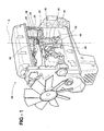
- an engine is generally indicated at 20.
- the engine 20 includes an engine block 22 with a bore formed within the engine block 22 defining a cylinder 24 extending along a first axis A.
- a piston assembly is generally shown at 26, and is disposed within the cylinder 24.
- the piston assembly 26 includes a piston head 28 having a top that extends circumferentially about the first axis A.
- a combustion bowl 30 is disposed on an upper surface of the top of the piston head 28.
- a ring belt 32 depends downwardly from the top in the direction of the first axis A.
- the ring belt 32 is cylindrical, depending downwardly from the periphery of the top of the piston head 28 and includes a plurality of ring grooves 34 extending circumferentially thereon for supporting a plurality of piston rings 74.
- a cylindrical ring belt 32 is shown, it will be understood that other geometries can be used, such as an oval shape, depending on the type of engine 20 and the shape of the cylinder 24 used.
- a piston gallery 35 is defined in the piston head 28, radially inward of the ring belt 32 and axially beneath the combustion bowl 30. The piston gallery 35 receives oil for cooling the piston during operation of the engine 20, and can be closed by a coverplate (not shown).
- a connecting rod 36 is pivotably connected about a second axis B to the piston head 28 and includes a shaft 38 and an attachment boss 40 disposed at a first end of the shaft 38, sometimes referred to as the small end.
- a crankshaft boss 42 At a second end of the shaft 38 is a crankshaft boss 42 defining a crankshaft bore 44.
- the crankshaft boss 42 is pivotably connected to a crank 46, which is in turn connected to a crankshaft 48.
- the piston head 28 is translatable along the first axis A within the cylinder 24, reciprocating between end points, referred to as piston stroke.
- the shaft 38 of the connecting rod 36 oscillates about the second axis B, turning the crank 46. This converts the reciprocating motion of the piston head 28 into rotational motion of the crankshaft 48, which can be used to rotate a set of vehicle wheels (not shown).
- the piston head 28 includes a pair of pin bosses 50 depending downwardly from the top, and disposed radially inward from the ring belt 32.
- a set of supports 52 secure the pin bosses 50 to the piston head 28.
- a pair of pin bores 54 are defined within the pin bosses 50 and are aligned axially with each other along the second axis B.
- the pin bores 54 are sized to receive a piston pin 56.
- the attachment boss 40 of the connecting rod 36 defines an attachment bore 58, and is aligned axially with the pin bores 54 along the second axis B.
- the attachment boss 40 is disposed between the pin bosses 50.
- the piston pin 56 extends along the second axis B and is inserted through the pin bores 54 and the attachment bore 58 of the attachment boss 40, to pivotably connect the connecting rod 36 to the piston head 28 about the second axis B.
- the connecting rod 36 is shown in isolation and includes a first guidance member 60 disposed on the shaft 38 to guide the piston head 28 during the piston stroke.
- the first guidance member 60 includes a first sliding surface 62 that engages a side wall of the cylinder 24.
- a second guidance member 64 is disposed on the shaft 38 and includes a second sliding surface 66.
- the first and second sliding surfaces 62, 66 each have an arcuate shape. As viewed from a perspective outside of the piston assembly 26, the first and second sliding surfaces 62, 66 form a convex arc. Extending downwardly between the top of the sliding surfaces 62, 66 and an intermediate point between the top and bottom, the first and second sliding surfaces 62, 66 curve away from the first axis A. Extending downwardly between the intermediate point and the bottom, the first and second sliding surfaces 62, 66 curve toward the first axis A.
- a first support rib 68 extends from the shaft 38 perpendicularly to the second axis B to connect the shaft 38 to the first guidance member 60.
- a second support rib 70 extends from the shaft 38 perpendicularly to the first axis A to connect the shaft 38 to the second guidance member 64.
- the first and second sliding surfaces 62, 66 are supported by the first and second support ribs 68, 70 and spaced perpendicularly from the first axis A, and from a centerline of the shaft 38, to contact the side walls of the cylinder 24 during the piston stroke.
- the first and second support ribs 68, 70 extend radially outwardly from the attachment boss 40, and the second guidance member 64 is spaced radially about the second axis B by approximately 180 degrees from the first guidance member 60.
- the intermediate point defining the outermost point of the convex arc on the sliding surfaces 62, 66 is aligned with the intersection between the first and second axes A, B, as well as the intersection between the centerline of the shaft 38 and the center of the attachment bore 58, such that the distances between the sliding surfaces 62, 66 is the greatest at the center of the attachment bore 58.
- the convex outer surface of the sliding surfaces 62, 66 contacts the side wall of the cylinder 24 at a point of contact, and the oscillating motion of the connecting rod 36 moves the point of contact to various different points along the first and second sliding surfaces 62, 66. Maintaining a point of contact prevents excess contact between the sliding surfaces 62, 66 and the side wall of the cylinder 24 from locking, or jamming, the piston assembly 26 within the cylinder 24.
- the first and second guidance members 60, 64 slide along the side walls of the engine 20 cylinders 24, just as a piston skirt (not shown) would.
- the piston assembly 26 in the exemplary embodiment lacks a piston skirt. Therefore, the first and second support ribs 68, 70 are designed to receive the side loads that are incurred during piston stroke and would normally be absorbed by a skirt.
- the first and second sliding surfaces 62, 66 are disposed substantially beneath the outer profile of the ring belt 32.
- a guidance member radius R 1 is defined as the distance between the first axis A and the outermost point of one of the sliding surfaces 62, 66 in a direction perpendicular to the first axis A.
- a piston head radius R 2 is defined as the distance between the first axis A and the outermost point of the ring belt 32 in a direction perpendicular to the first axis A.
- the guidance member radius R 1 is substantially the same as the piston head radius R 2 . According to the exemplary embodiment, the guidance member radius R 1 is within approximately ⁇ 5% of the piston head radius R 2 , so, for example, if the piston head radius R 2 is 500 millimeters, then the guidance member radius R 1 would be between approximately 475 millimeters and 525 millimeters.
- first and second sliding surfaces 62, 66 could be accommodated with a friction reducing coating, or with a bearing surface, such as a rolling or sliding bearing. Additionally, just as the shape of the ring belt 32 could differ, the geometry of the first and second sliding surfaces 62, 66 would need to accommodate the specific shape of the cylinder 24, depending on the type of engine 20 used.
- the piston head 28 is constructed without a skirt, and the size of the ring belt 32 depending from the periphery of the piston head 28 needs only to be necessary to support the desired number of piston rings 74.
- the ring belt 32 includes a lower distal edge 72 disposed, in the direction of the first axis A, below the lower-most piston ring 74.
- the lower distal edge 72 does not need to extend, in the direction of the first axis A, beyond the center of the pin bores 54.
- the lower distal edge 72 extends, in the direction of the first axis A, no further than the top of the pin bores 54.
- the lower distal edge 72 can extend to some point intermediate the top of the pin bores 54 and the center of the pin bores 54.
- the connecting rod 36 could include a ring 74 surrounding the first and second guidance members 60, 64.
- a coating surface can be provided on said first and second guidance members 60, 64 radially inward of said ring 74 allowing the connecting rod 36 to slide relative to the ring as it oscillates during the piston stroke.
- the first and second sliding surfaces 62, 66 are disposed on the outer surface of the ring 74 to engage the cylinder 24 along the piston stroke.
- the ring 74 could optionally include a split 78 for manufacturing and installation purposes.
Landscapes
- Engineering & Computer Science (AREA)
- General Engineering & Computer Science (AREA)
- Mechanical Engineering (AREA)
- Pistons, Piston Rings, And Cylinders (AREA)
Claims (12)
- Verbindungstange (36) für eine Kolbenanordnung mit:einem Schaft (38), der sich zwischen einem ersten Ende und einem zweiten Ende erstreckt,einer Anbringnabe (40), die an dem ersten Ende des Schafts (38) vorgesehen ist, die darin eine Anbringbohrung (58) definiert, um einen Kolbenbolzen (56) aufzunehmen, undFührungselementen (60, 64), die sich von dem Schaft erstrecken und eine Gleitoberfläche (62, 66) aufweisen, um mit einer Wand eines Zylinders (24) in Eingriff zu treten,wobei die Stange (36) ein erstes Führungselement (60) mit einer ersten Gleitoberfläche (62) zum In-Eingriff-Treten mit einem ersten Abschnitt der Seitenwand des Zylinders (24) und ein zweites Führungselement (64) aufweist, welches eine zweite Gleitoberfläche (66) aufweist, um mit einem zweiten Abschnitt der Seitenwand des Zylinders (24) in Eingriff zu treten, undferner mit einer ersten Stützrippe (68), die sich von dem Schaft (38) erstreckt, die den Schaft (38) mit dem ersten Führungselement (60) verbindet, und mit einer zweiten Stützrippe (70), die sich von dem Schaft (38) erstreckt, die den Schaft (38) mit dem zweiten Führungselement (64) verbindet,wobei die ersten und zweiten Gleitoberflächen (62, 66) senkrecht von einer Mittellinie des Schafts (38) beabstandet sind,wobei sich die ersten und zweiten Stützrippen radial von der Anbringnabe nach außen erstrecken,wobei die Gleitoberfläche (62, 66) als eine gekrümmte Oberfläche definiert ist,und wobei ein erster Abstand auf einer Linie zwischen der ersten Gleitoberfläche (62) und der zweiten Gleitoberfläche (66) senkrecht zu einer Mittellinie des Schafts definiert ist und welcher durch einen Schnittpunkt der Mittellinie und die Mitte der Anbringbohrung hindurchtritt und wobei der erste Abstand größer ist als jeder andere Abstand, der auf einer Linie zwischen den ersten und zweiten Gleitoberflächen senkrecht zu der Mittellinie definiert ist, welche einen konvexen Bogen entlang der ersten und zweiten Gleitoberflächen definiert,dadurch gekennzeichnet, dassdie erste Stützrippe (68) radial bezüglich der Anbringnabe (40) um ungefähr 180° von der ersten Stützrippe (70) beabstandet ist.
- Verbindungsstange (36) nach Anspruch 1, mit einem Ring (74), der separat von dem Paar Führungselemente ausgebildet ist und diese umgibt.
- Verbindungsstange (36) nach Anspruch 2, mit einer Beschichtungsoberfläche, die auf dem Paar Führungselemente vorgesehen ist.
- Verbindungsstange (36) nach einem der vorhergehenden Ansprüche, bei dem das Paar Führungselemente als ein einziges Stück mit der Anbringnabe (40) hergestellt ist.
- Verbindungsstange (36) nach einem der vorhergehenden Ansprüche, mit einer Kurbelwellennabe (42), die eine Kurbelwellenbohrung am zweiten Ende des Schafts (38) definiert, um den Schaft mit einer Kurbel zu verbinden.
- Kolbenanordnung mit:einem Kolbenboden (28) zum Hin- und Herbewegen innerhalb eines Zylinders (24) entlang einer ersten Achse und einem Paar Bolzennaben (50), die sich nach unten von dem Kolbenboden (28) in der Richtung der ersten Achse erstrecken und die Bolzenbohrungen (54) definieren, die darin axial miteinander fluchten, sodass sie eine zweite Achse definieren,einer Verbindungsstange (36) nach einem der vorhergehenden Ansprüche, deren Anbringnabe (40) eine Anbringbohrung zur axialen Ausrichtung mit den Bolzennaben des Kolbenbodens definiert, wobei ein Kolbenbolzen die Verbindungsstange (36) mit dem Kolbenboden (28) um die zweite Achse verschwenkbar verbindet.
- Anordnung nach Anspruch 6 mit einem Ringfeld (34), das sich nach unten von einem radialen Umfang des Kolbenbodens erstreckt, wobei das Ringfeld eine untere distale Kante (72) aufweist, die sich in der Richtung der ersten Achse erstreckt und sich nicht weiter als bis zu einer Mitte der Bolzenbohrungen erstreckt.
- Anordnung nach Anspruch 7, bei dem sich die untere distale Kante (72) um die erste Achse herum erstreckt und sie zwischen einem Oberteil der Bolzenbohrungen (54) und einer Mitte der Bolzenbohrungen (54) endet.
- Anordnung nach Anspruch 7 oder 8, mit einem Führungselementradius (R1), der als der Abstand zwischen der ersten Achse und einem äußersten Punkt der Gleitoberfläche definiert ist, und mit einem Kolbenbodenradius (R2), der als der Abstand zwischen der ersten Achse und einem äußersten Punkt des Ringfelds definiert ist, und wobei der Führungselementradius im Wesentlichen der gleiche ist wie der Kolbenbodenradius.
- Kolbenanordnung mit:einem Kolbenboden (26) zum Hin- und Herbewegen innerhalb eines Zylinders (24) entlang einer ersten Achse und mit einem Oberteil, das sich um die erste Achse herum umfänglich erstreckt,wobei der Kolbenboden (26) ein Ringfeld (34) aufweist, das sich von dem Oberteil in der Richtung der ersten Achse nach unten erstreckt,wobei der Kolbenboden (26) ein Paar Bolzennaben (50) aufweist, die sich von dem Oberteil in der Richtung der ersten Achse nach unten erstrecken und die radial innerhalb des Ringfelds (34) vorgesehen sind und wobei die Bolzennaben Bolzenbohrungen darin definieren, die axial miteinander fluchten, welche eine zweite Achse senkrecht zu der ersten Achse definieren,einer Verbindungsstange (36) nach einem der vorhergehenden Ansprüche 1 bis 5, deren Anbringnabe (58) eine Anbringbohrung definiert, die axial mit den Bolzenbohrungen fluchtet und die zwischen den Bolzennaben vorgesehen ist,wobei ein Kolbenbolzen (56) entlang der zweiten Achse radial innerhalb der Bolzenbohrungen eingeführt ist und wobei die Anbringbohrung des Schafts die Verbindungsstange (36) um die zweite Achse herum verschwenkbar mit dem Kolbenboden verbindet.
- Motor mit:einem Motorblock (20) mit wenigstens einer Bohrung darin ausgebildet, die einen Zylinder definiert, der sich entlang einer ersten Achse erstreckt,einer Kolbenanordnung, die gleitbar innerhalb des Zylinders vorgesehen ist, um sich linear innerhalb des Zylinders entlang eines Kolbenhubs hin- und herzubewegen,wobei die Kolbenanordnung einen Kolbenboden (24) und eine Verbindungsstange (36) aufweist, die mit dem Kolbenboden verbunden ist,wobei die Verbindungsstange eine Verbindungsstange nach einem der Ansprüche 1 bis 5 ist.
- Verfahren zum Führen einer Kolbenanordnung innerhalb eines Zylinders eines Motors mit den Schritten des:linearen Hin- und Herbewegens eines Kolbenbodens (24) entlang eines Kolbenhubs, der entlang einer ersten Achse innerhalb des Zylinders definiert ist,Verschwenkens einer Verbindungsstange (36) um eine zweite Achse senkrecht zu der ersten Achse bezüglich des Kolbenbodens (24) undGleitens eines Abschnitts der Verbindungsstange (36) entlang einer Seitenwand des Zylinders (24), um den Kolbenboden zu führen,wobei die Verbindungsstange (36) eine Verbindungsstange nach einem der Ansprüche 1 bis 5 ist.
Applications Claiming Priority (2)
| Application Number | Priority Date | Filing Date | Title |
|---|---|---|---|
| US11/835,489 US7647911B2 (en) | 2007-08-08 | 2007-08-08 | Small end con rod guidance piston |
| PCT/US2008/072416 WO2009021089A2 (en) | 2007-08-08 | 2008-08-07 | Small end con rod guidance piston |
Publications (3)
| Publication Number | Publication Date |
|---|---|
| EP2183492A2 EP2183492A2 (de) | 2010-05-12 |
| EP2183492A4 EP2183492A4 (de) | 2011-12-14 |
| EP2183492B1 true EP2183492B1 (de) | 2014-09-17 |
Family
ID=40342032
Family Applications (1)
| Application Number | Title | Priority Date | Filing Date |
|---|---|---|---|
| EP08797337.6A Not-in-force EP2183492B1 (de) | 2007-08-08 | 2008-08-07 | Führungskolben mit pleuelkopf |
Country Status (7)
| Country | Link |
|---|---|
| US (1) | US7647911B2 (de) |
| EP (1) | EP2183492B1 (de) |
| JP (1) | JP2010535994A (de) |
| KR (1) | KR20100061667A (de) |
| CN (1) | CN101809298B (de) |
| BR (1) | BRPI0815022A2 (de) |
| WO (1) | WO2009021089A2 (de) |
Families Citing this family (9)
| Publication number | Priority date | Publication date | Assignee | Title |
|---|---|---|---|---|
| EP2726724B1 (de) * | 2011-06-29 | 2018-08-22 | Federal-Mogul LLC | Kolben mit einer unterbodenträgerfunktion |
| US9004037B2 (en) * | 2012-02-20 | 2015-04-14 | Federal-Mogul Corporation | Piston assembly for internal combustion engine |
| US10012285B2 (en) | 2014-09-29 | 2018-07-03 | Mazda Motor Corporation | Reciprocal rotation mechanism of engine |
| CN104389679A (zh) * | 2014-11-20 | 2015-03-04 | 湖南江滨机器(集团)有限责任公司 | 发动机及其活塞连杆组 |
| GB2541096B (en) * | 2015-07-10 | 2018-11-28 | Ford Global Tech Llc | Bearing interface with recesses to reduce friction |
| CN106948965B (zh) * | 2017-02-20 | 2019-11-19 | 浙江大学 | 一种发动机活塞结构 |
| JP6593373B2 (ja) * | 2017-03-06 | 2019-10-23 | マツダ株式会社 | 往復動ピストンエンジンのピストン構造 |
| JP6465129B2 (ja) * | 2017-03-06 | 2019-02-06 | マツダ株式会社 | 往復動ピストンエンジン |
| CN110671229A (zh) * | 2019-11-20 | 2020-01-10 | 湖南江滨机器(集团)有限责任公司 | 一种活塞连杆组件 |
Family Cites Families (27)
| Publication number | Priority date | Publication date | Assignee | Title |
|---|---|---|---|---|
| US1770818A (en) * | 1927-05-11 | 1930-07-15 | Gen Motors Corp | Piston |
| US1926329A (en) * | 1930-09-18 | 1933-09-12 | Wright Aeronautical Corp | Piston |
| US2315403A (en) * | 1940-09-24 | 1943-03-30 | Aluminum Co Of America | Composite piston |
| US3007755A (en) * | 1959-01-23 | 1961-11-07 | Daub Rudolph | Piston |
| US3259028A (en) * | 1964-03-20 | 1966-07-05 | Ford Motor Co | Piston |
| US4013057A (en) * | 1975-05-14 | 1977-03-22 | Dana Corporation | Piston assembly |
| BR7806090A (pt) * | 1978-09-15 | 1980-03-25 | Metal Leve Sa Ind Com | Pistao com saia independente |
| JPS5768137U (de) * | 1980-10-13 | 1982-04-23 | ||
| DE3039382A1 (de) | 1980-10-18 | 1982-04-22 | Mahle Gmbh, 7000 Stuttgart | Leichter tachkolben fuer verbrennungsmotoren |
| DE3210771A1 (de) * | 1982-03-24 | 1983-09-29 | Günter 8543 Hilpoltstein Elsbett | Kolbentrieb fuer hubkolben-brennkraftmaschinen, wie dieselmotoren u.a. |
| JPS59153951A (ja) | 1983-02-21 | 1984-09-01 | Toyota Motor Corp | コネクテイングロツド一体型ピストン |
| DE3338419A1 (de) * | 1983-10-22 | 1985-05-02 | Mtu Motoren- Und Turbinen-Union Friedrichshafen Gmbh, 7990 Friedrichshafen | Kolben fuer eine hubkolbenbrennkraftmaschine |
| GB8403522D0 (en) * | 1984-02-10 | 1984-03-14 | Ae Plc | Pistons |
| DE3601503A1 (de) * | 1986-01-20 | 1987-07-23 | Kolbenschmidt Ag | Pleuelstange fuer hubkolbenmaschinen mit kugelsegmentfoermiger fuehrung im zylinder |
| DE3621421C1 (de) * | 1986-06-26 | 1987-12-10 | Duesterloh Gmbh | Kolbenmaschine |
| JPH03199658A (ja) * | 1989-12-26 | 1991-08-30 | Nissan Motor Co Ltd | コネクティングロッド一体型ピストン |
| US5112145A (en) * | 1990-01-18 | 1992-05-12 | Detroit Diesel Corporation | Piston and bearing assemblies |
| JPH0476257A (ja) | 1990-07-17 | 1992-03-11 | Nissan Motor Co Ltd | 内燃機関のピストン |
| JPH05272639A (ja) | 1992-03-30 | 1993-10-19 | Nissan Motor Co Ltd | 繊維強化プラスチック製ピストン |
| JPH0738648U (ja) * | 1993-12-20 | 1995-07-14 | 株式会社ユニシアジェックス | 内燃機関用ピストン |
| GB9609931D0 (en) * | 1996-05-13 | 1996-07-17 | Broadsuper Ltd | Internal combustion engines |
| US6260472B1 (en) * | 1998-07-28 | 2001-07-17 | Federal-Mogul World Wide, Inc. | One-piece integral skirt piston and method of making the same |
| GB9908844D0 (en) * | 1999-04-19 | 1999-06-16 | Seneca Tech Ltd | Piston-connecting rod retention |
| US6499387B2 (en) * | 2001-03-06 | 2002-12-31 | Federal-Mogul World Wide, Inc. | Unified multi-piece piston and method of manufacture |
| US6825450B2 (en) * | 2002-11-06 | 2004-11-30 | Federal-Mogul World Wide, Inc. | Piston and method of manufacture |
| US6973723B2 (en) * | 2003-01-08 | 2005-12-13 | International Engine Intellectual Property Company, Llc | Piston formed by powder metallurgical methods |
| US6715457B1 (en) * | 2003-03-20 | 2004-04-06 | Federal-Mogul World Wide, Inc. | Piston assembly |
-
2007
- 2007-08-08 US US11/835,489 patent/US7647911B2/en not_active Expired - Fee Related
-
2008
- 2008-08-07 JP JP2010520297A patent/JP2010535994A/ja active Pending
- 2008-08-07 WO PCT/US2008/072416 patent/WO2009021089A2/en not_active Ceased
- 2008-08-07 CN CN2008801093542A patent/CN101809298B/zh not_active Expired - Fee Related
- 2008-08-07 KR KR1020107005092A patent/KR20100061667A/ko not_active Ceased
- 2008-08-07 BR BRPI0815022-2A2A patent/BRPI0815022A2/pt not_active IP Right Cessation
- 2008-08-07 EP EP08797337.6A patent/EP2183492B1/de not_active Not-in-force
Also Published As
| Publication number | Publication date |
|---|---|
| BRPI0815022A2 (pt) | 2015-03-10 |
| EP2183492A4 (de) | 2011-12-14 |
| JP2010535994A (ja) | 2010-11-25 |
| US20090038577A1 (en) | 2009-02-12 |
| KR20100061667A (ko) | 2010-06-08 |
| CN101809298A (zh) | 2010-08-18 |
| WO2009021089A3 (en) | 2009-04-16 |
| EP2183492A2 (de) | 2010-05-12 |
| US7647911B2 (en) | 2010-01-19 |
| CN101809298B (zh) | 2012-06-27 |
| WO2009021089A2 (en) | 2009-02-12 |
Similar Documents
| Publication | Publication Date | Title |
|---|---|---|
| EP2183492B1 (de) | Führungskolben mit pleuelkopf | |
| EP1934455B1 (de) | Kolben mit verbesserten kühleigenschaften | |
| US6279456B1 (en) | Piston | |
| JP6668377B2 (ja) | 低いコンプレッションハイトを有する、頑丈かつ軽量のピストンおよびその構成方法 | |
| US10119613B2 (en) | Wrist pin and method of reducing wear between members thereof, connecting rod, piston and methods of constructing same | |
| EP0613531A1 (de) | Wälzlagerkäfig | |
| US7954421B2 (en) | Lightweight piston | |
| EP2438316B1 (de) | Pleuelstange mit bohrung | |
| US5144884A (en) | Two-part piston assembly device | |
| US7383808B1 (en) | Articulated piston skirt | |
| US20140000453A1 (en) | Piston with Cooling Gallery and Closed Collar Chamber | |
| US6945213B2 (en) | Cylinder block for multicylinder engine | |
| KR20080071117A (ko) | 링 그루부 아래에 배치된 둘레로 진행하는 방사상 홈을구비한 피스톤 | |
| KR20060123586A (ko) | 내연 기관의 피스톤용 피스톤 핀 베어링 | |
| EP1529992B1 (de) | Brennkraftmaschine und Pleuelstange dafür | |
| FI120947B (fi) | Männän ja kiertokangen käsittävä polttomoottorikoneen käyttökoneisto | |
| US9470311B2 (en) | Lightweight engine power cell assembly | |
| US4928578A (en) | Pistons with bearing members | |
| US7938058B2 (en) | Engine piston with rolling element skirt | |
| EP0351977A2 (de) | Kolben | |
| KR102671590B1 (ko) | 내연 기관의 피스톤 조립체 | |
| US8443715B2 (en) | Piston-pin bore dimensions for a piston of an internal combustion engine | |
| US20110197847A1 (en) | Connecting rod-piston group | |
| GB2198210A (en) | Pistons | |
| JP2003035308A (ja) | V型エンジンのコネクティングロッド構造 |
Legal Events
| Date | Code | Title | Description |
|---|---|---|---|
| PUAI | Public reference made under article 153(3) epc to a published international application that has entered the european phase |
Free format text: ORIGINAL CODE: 0009012 |
|
| 17P | Request for examination filed |
Effective date: 20100301 |
|
| AK | Designated contracting states |
Kind code of ref document: A2 Designated state(s): AT BE BG CH CY CZ DE DK EE ES FI FR GB GR HR HU IE IS IT LI LT LU LV MC MT NL NO PL PT RO SE SI SK TR |
|
| AX | Request for extension of the european patent |
Extension state: AL BA MK RS |
|
| A4 | Supplementary search report drawn up and despatched |
Effective date: 20111115 |
|
| RIC1 | Information provided on ipc code assigned before grant |
Ipc: F02B 77/00 20060101ALI20111109BHEP Ipc: F02F 3/00 20060101ALI20111109BHEP Ipc: F16C 7/02 20060101AFI20111109BHEP Ipc: F16J 1/14 20060101ALI20111109BHEP |
|
| DAX | Request for extension of the european patent (deleted) | ||
| GRAP | Despatch of communication of intention to grant a patent |
Free format text: ORIGINAL CODE: EPIDOSNIGR1 |
|
| INTG | Intention to grant announced |
Effective date: 20140307 |
|
| GRAS | Grant fee paid |
Free format text: ORIGINAL CODE: EPIDOSNIGR3 |
|
| GRAA | (expected) grant |
Free format text: ORIGINAL CODE: 0009210 |
|
| AK | Designated contracting states |
Kind code of ref document: B1 Designated state(s): AT BE BG CH CY CZ DE DK EE ES FI FR GB GR HR HU IE IS IT LI LT LU LV MC MT NL NO PL PT RO SE SI SK TR |
|
| REG | Reference to a national code |
Ref country code: GB Ref legal event code: FG4D |
|
| REG | Reference to a national code |
Ref country code: CH Ref legal event code: EP |
|
| REG | Reference to a national code |
Ref country code: IE Ref legal event code: FG4D |
|
| REG | Reference to a national code |
Ref country code: AT Ref legal event code: REF Ref document number: 687849 Country of ref document: AT Kind code of ref document: T Effective date: 20141015 |
|
| REG | Reference to a national code |
Ref country code: SE Ref legal event code: TRGR |
|
| REG | Reference to a national code |
Ref country code: DE Ref legal event code: R096 Ref document number: 602008034468 Country of ref document: DE Effective date: 20141030 |
|
| PG25 | Lapsed in a contracting state [announced via postgrant information from national office to epo] |
Ref country code: LT Free format text: LAPSE BECAUSE OF FAILURE TO SUBMIT A TRANSLATION OF THE DESCRIPTION OR TO PAY THE FEE WITHIN THE PRESCRIBED TIME-LIMIT Effective date: 20140917 Ref country code: GR Free format text: LAPSE BECAUSE OF FAILURE TO SUBMIT A TRANSLATION OF THE DESCRIPTION OR TO PAY THE FEE WITHIN THE PRESCRIBED TIME-LIMIT Effective date: 20141218 Ref country code: NO Free format text: LAPSE BECAUSE OF FAILURE TO SUBMIT A TRANSLATION OF THE DESCRIPTION OR TO PAY THE FEE WITHIN THE PRESCRIBED TIME-LIMIT Effective date: 20141217 Ref country code: FI Free format text: LAPSE BECAUSE OF FAILURE TO SUBMIT A TRANSLATION OF THE DESCRIPTION OR TO PAY THE FEE WITHIN THE PRESCRIBED TIME-LIMIT Effective date: 20140917 |
|
| REG | Reference to a national code |
Ref country code: NL Ref legal event code: VDEP Effective date: 20140917 |
|
| REG | Reference to a national code |
Ref country code: LT Ref legal event code: MG4D |
|
| PG25 | Lapsed in a contracting state [announced via postgrant information from national office to epo] |
Ref country code: CY Free format text: LAPSE BECAUSE OF FAILURE TO SUBMIT A TRANSLATION OF THE DESCRIPTION OR TO PAY THE FEE WITHIN THE PRESCRIBED TIME-LIMIT Effective date: 20140917 Ref country code: HR Free format text: LAPSE BECAUSE OF FAILURE TO SUBMIT A TRANSLATION OF THE DESCRIPTION OR TO PAY THE FEE WITHIN THE PRESCRIBED TIME-LIMIT Effective date: 20140917 Ref country code: LV Free format text: LAPSE BECAUSE OF FAILURE TO SUBMIT A TRANSLATION OF THE DESCRIPTION OR TO PAY THE FEE WITHIN THE PRESCRIBED TIME-LIMIT Effective date: 20140917 |
|
| REG | Reference to a national code |
Ref country code: AT Ref legal event code: MK05 Ref document number: 687849 Country of ref document: AT Kind code of ref document: T Effective date: 20140917 |
|
| PG25 | Lapsed in a contracting state [announced via postgrant information from national office to epo] |
Ref country code: NL Free format text: LAPSE BECAUSE OF FAILURE TO SUBMIT A TRANSLATION OF THE DESCRIPTION OR TO PAY THE FEE WITHIN THE PRESCRIBED TIME-LIMIT Effective date: 20140917 |
|
| PG25 | Lapsed in a contracting state [announced via postgrant information from national office to epo] |
Ref country code: EE Free format text: LAPSE BECAUSE OF FAILURE TO SUBMIT A TRANSLATION OF THE DESCRIPTION OR TO PAY THE FEE WITHIN THE PRESCRIBED TIME-LIMIT Effective date: 20140917 Ref country code: CZ Free format text: LAPSE BECAUSE OF FAILURE TO SUBMIT A TRANSLATION OF THE DESCRIPTION OR TO PAY THE FEE WITHIN THE PRESCRIBED TIME-LIMIT Effective date: 20140917 Ref country code: SK Free format text: LAPSE BECAUSE OF FAILURE TO SUBMIT A TRANSLATION OF THE DESCRIPTION OR TO PAY THE FEE WITHIN THE PRESCRIBED TIME-LIMIT Effective date: 20140917 Ref country code: RO Free format text: LAPSE BECAUSE OF FAILURE TO SUBMIT A TRANSLATION OF THE DESCRIPTION OR TO PAY THE FEE WITHIN THE PRESCRIBED TIME-LIMIT Effective date: 20140917 Ref country code: ES Free format text: LAPSE BECAUSE OF FAILURE TO SUBMIT A TRANSLATION OF THE DESCRIPTION OR TO PAY THE FEE WITHIN THE PRESCRIBED TIME-LIMIT Effective date: 20140917 Ref country code: PT Free format text: LAPSE BECAUSE OF FAILURE TO SUBMIT A TRANSLATION OF THE DESCRIPTION OR TO PAY THE FEE WITHIN THE PRESCRIBED TIME-LIMIT Effective date: 20150119 Ref country code: IS Free format text: LAPSE BECAUSE OF FAILURE TO SUBMIT A TRANSLATION OF THE DESCRIPTION OR TO PAY THE FEE WITHIN THE PRESCRIBED TIME-LIMIT Effective date: 20150117 |
|
| PG25 | Lapsed in a contracting state [announced via postgrant information from national office to epo] |
Ref country code: AT Free format text: LAPSE BECAUSE OF FAILURE TO SUBMIT A TRANSLATION OF THE DESCRIPTION OR TO PAY THE FEE WITHIN THE PRESCRIBED TIME-LIMIT Effective date: 20140917 Ref country code: PL Free format text: LAPSE BECAUSE OF FAILURE TO SUBMIT A TRANSLATION OF THE DESCRIPTION OR TO PAY THE FEE WITHIN THE PRESCRIBED TIME-LIMIT Effective date: 20140917 |
|
| REG | Reference to a national code |
Ref country code: DE Ref legal event code: R097 Ref document number: 602008034468 Country of ref document: DE |
|
| PLBE | No opposition filed within time limit |
Free format text: ORIGINAL CODE: 0009261 |
|
| STAA | Information on the status of an ep patent application or granted ep patent |
Free format text: STATUS: NO OPPOSITION FILED WITHIN TIME LIMIT |
|
| PG25 | Lapsed in a contracting state [announced via postgrant information from national office to epo] |
Ref country code: DK Free format text: LAPSE BECAUSE OF FAILURE TO SUBMIT A TRANSLATION OF THE DESCRIPTION OR TO PAY THE FEE WITHIN THE PRESCRIBED TIME-LIMIT Effective date: 20140917 |
|
| 26N | No opposition filed |
Effective date: 20150618 |
|
| PG25 | Lapsed in a contracting state [announced via postgrant information from national office to epo] |
Ref country code: SI Free format text: LAPSE BECAUSE OF FAILURE TO SUBMIT A TRANSLATION OF THE DESCRIPTION OR TO PAY THE FEE WITHIN THE PRESCRIBED TIME-LIMIT Effective date: 20140917 |
|
| PG25 | Lapsed in a contracting state [announced via postgrant information from national office to epo] |
Ref country code: MC Free format text: LAPSE BECAUSE OF FAILURE TO SUBMIT A TRANSLATION OF THE DESCRIPTION OR TO PAY THE FEE WITHIN THE PRESCRIBED TIME-LIMIT Effective date: 20140917 Ref country code: LU Free format text: LAPSE BECAUSE OF FAILURE TO SUBMIT A TRANSLATION OF THE DESCRIPTION OR TO PAY THE FEE WITHIN THE PRESCRIBED TIME-LIMIT Effective date: 20150807 |
|
| REG | Reference to a national code |
Ref country code: CH Ref legal event code: PL |
|
| GBPC | Gb: european patent ceased through non-payment of renewal fee |
Effective date: 20150807 |
|
| PG25 | Lapsed in a contracting state [announced via postgrant information from national office to epo] |
Ref country code: LI Free format text: LAPSE BECAUSE OF NON-PAYMENT OF DUE FEES Effective date: 20150831 Ref country code: CH Free format text: LAPSE BECAUSE OF NON-PAYMENT OF DUE FEES Effective date: 20150831 |
|
| REG | Reference to a national code |
Ref country code: IE Ref legal event code: MM4A |
|
| REG | Reference to a national code |
Ref country code: FR Ref legal event code: PLFP Year of fee payment: 9 |
|
| PG25 | Lapsed in a contracting state [announced via postgrant information from national office to epo] |
Ref country code: GB Free format text: LAPSE BECAUSE OF NON-PAYMENT OF DUE FEES Effective date: 20150807 Ref country code: IE Free format text: LAPSE BECAUSE OF NON-PAYMENT OF DUE FEES Effective date: 20150807 |
|
| PG25 | Lapsed in a contracting state [announced via postgrant information from national office to epo] |
Ref country code: MT Free format text: LAPSE BECAUSE OF FAILURE TO SUBMIT A TRANSLATION OF THE DESCRIPTION OR TO PAY THE FEE WITHIN THE PRESCRIBED TIME-LIMIT Effective date: 20140917 |
|
| PG25 | Lapsed in a contracting state [announced via postgrant information from national office to epo] |
Ref country code: BG Free format text: LAPSE BECAUSE OF FAILURE TO SUBMIT A TRANSLATION OF THE DESCRIPTION OR TO PAY THE FEE WITHIN THE PRESCRIBED TIME-LIMIT Effective date: 20140917 Ref country code: HU Free format text: LAPSE BECAUSE OF FAILURE TO SUBMIT A TRANSLATION OF THE DESCRIPTION OR TO PAY THE FEE WITHIN THE PRESCRIBED TIME-LIMIT; INVALID AB INITIO Effective date: 20080807 |
|
| REG | Reference to a national code |
Ref country code: FR Ref legal event code: PLFP Year of fee payment: 10 |
|
| PG25 | Lapsed in a contracting state [announced via postgrant information from national office to epo] |
Ref country code: TR Free format text: LAPSE BECAUSE OF FAILURE TO SUBMIT A TRANSLATION OF THE DESCRIPTION OR TO PAY THE FEE WITHIN THE PRESCRIBED TIME-LIMIT Effective date: 20140917 |
|
| PG25 | Lapsed in a contracting state [announced via postgrant information from national office to epo] |
Ref country code: BE Free format text: LAPSE BECAUSE OF FAILURE TO SUBMIT A TRANSLATION OF THE DESCRIPTION OR TO PAY THE FEE WITHIN THE PRESCRIBED TIME-LIMIT Effective date: 20140917 |
|
| REG | Reference to a national code |
Ref country code: DE Ref legal event code: R082 Ref document number: 602008034468 Country of ref document: DE Representative=s name: HOFFMANN - EITLE PATENT- UND RECHTSANWAELTE PA, DE Ref country code: DE Ref legal event code: R081 Ref document number: 602008034468 Country of ref document: DE Owner name: FEDERAL-MOGUL LLC (N. D. GES. D. STAATES DELAW, US Free format text: FORMER OWNER: FEDERAL-MOGUL CORP., SOUTHFIELD, MICH., US |
|
| REG | Reference to a national code |
Ref country code: FR Ref legal event code: PLFP Year of fee payment: 11 |
|
| PGFP | Annual fee paid to national office [announced via postgrant information from national office to epo] |
Ref country code: FR Payment date: 20180718 Year of fee payment: 11 Ref country code: IT Payment date: 20180814 Year of fee payment: 11 Ref country code: DE Payment date: 20180716 Year of fee payment: 11 |
|
| PGFP | Annual fee paid to national office [announced via postgrant information from national office to epo] |
Ref country code: SE Payment date: 20180810 Year of fee payment: 11 |
|
| REG | Reference to a national code |
Ref country code: DE Ref legal event code: R119 Ref document number: 602008034468 Country of ref document: DE |
|
| REG | Reference to a national code |
Ref country code: SE Ref legal event code: EUG |
|
| PG25 | Lapsed in a contracting state [announced via postgrant information from national office to epo] |
Ref country code: SE Free format text: LAPSE BECAUSE OF NON-PAYMENT OF DUE FEES Effective date: 20190808 |
|
| PG25 | Lapsed in a contracting state [announced via postgrant information from national office to epo] |
Ref country code: DE Free format text: LAPSE BECAUSE OF NON-PAYMENT OF DUE FEES Effective date: 20200303 Ref country code: FR Free format text: LAPSE BECAUSE OF NON-PAYMENT OF DUE FEES Effective date: 20190831 |
|
| PG25 | Lapsed in a contracting state [announced via postgrant information from national office to epo] |
Ref country code: IT Free format text: LAPSE BECAUSE OF NON-PAYMENT OF DUE FEES Effective date: 20190807 |