EP2183885B1 - Netzwerkumkonfigurationsverfahren - Google Patents
Netzwerkumkonfigurationsverfahren Download PDFInfo
- Publication number
- EP2183885B1 EP2183885B1 EP07802598A EP07802598A EP2183885B1 EP 2183885 B1 EP2183885 B1 EP 2183885B1 EP 07802598 A EP07802598 A EP 07802598A EP 07802598 A EP07802598 A EP 07802598A EP 2183885 B1 EP2183885 B1 EP 2183885B1
- Authority
- EP
- European Patent Office
- Prior art keywords
- data unit
- bridge
- topology
- communication network
- procedure
- Prior art date
- Legal status (The legal status is an assumption and is not a legal conclusion. Google has not performed a legal analysis and makes no representation as to the accuracy of the status listed.)
- Not-in-force
Links
- 238000000034 method Methods 0.000 title claims abstract description 121
- 238000010926 purge Methods 0.000 claims abstract description 73
- 238000004891 communication Methods 0.000 claims abstract description 35
- 230000011664 signaling Effects 0.000 claims description 12
- 238000012423 maintenance Methods 0.000 claims description 7
- 230000015556 catabolic process Effects 0.000 claims description 3
- 238000006731 degradation reaction Methods 0.000 claims description 3
- 230000000977 initiatory effect Effects 0.000 claims description 3
- 238000012545 processing Methods 0.000 claims description 3
- 230000008859 change Effects 0.000 description 10
- 238000004590 computer program Methods 0.000 description 8
- 238000011084 recovery Methods 0.000 description 8
- 230000001276 controlling effect Effects 0.000 description 7
- 230000008569 process Effects 0.000 description 6
- 238000001914 filtration Methods 0.000 description 4
- 238000011010 flushing procedure Methods 0.000 description 4
- 230000001960 triggered effect Effects 0.000 description 4
- DWSYCUKCNSVBRA-UHFFFAOYSA-N 4-(5-methylsulfonyltetrazol-1-yl)phenol Chemical compound CS(=O)(=O)C1=NN=NN1C1=CC=C(C=C1)O DWSYCUKCNSVBRA-UHFFFAOYSA-N 0.000 description 3
- 101710167643 Serine/threonine protein phosphatase PstP Proteins 0.000 description 3
- 238000012217 deletion Methods 0.000 description 3
- 230000037430 deletion Effects 0.000 description 3
- 230000000694 effects Effects 0.000 description 3
- 238000001514 detection method Methods 0.000 description 2
- 238000005562 fading Methods 0.000 description 2
- 230000009467 reduction Effects 0.000 description 2
- 230000004044 response Effects 0.000 description 2
- 108091064702 1 family Proteins 0.000 description 1
- 240000004752 Laburnum anagyroides Species 0.000 description 1
- 230000009471 action Effects 0.000 description 1
- 230000008901 benefit Effects 0.000 description 1
- 238000006243 chemical reaction Methods 0.000 description 1
- 230000007547 defect Effects 0.000 description 1
- 230000002950 deficient Effects 0.000 description 1
- 230000001419 dependent effect Effects 0.000 description 1
- 230000000670 limiting effect Effects 0.000 description 1
- 239000003550 marker Substances 0.000 description 1
- 230000003278 mimic effect Effects 0.000 description 1
- 230000000737 periodic effect Effects 0.000 description 1
- 230000001105 regulatory effect Effects 0.000 description 1
- 230000000717 retained effect Effects 0.000 description 1
Images




Classifications
-
- H—ELECTRICITY
- H04—ELECTRIC COMMUNICATION TECHNIQUE
- H04L—TRANSMISSION OF DIGITAL INFORMATION, e.g. TELEGRAPHIC COMMUNICATION
- H04L12/00—Data switching networks
- H04L12/28—Data switching networks characterised by path configuration, e.g. LAN [Local Area Networks] or WAN [Wide Area Networks]
- H04L12/42—Loop networks
- H04L12/437—Ring fault isolation or reconfiguration
-
- H—ELECTRICITY
- H04—ELECTRIC COMMUNICATION TECHNIQUE
- H04L—TRANSMISSION OF DIGITAL INFORMATION, e.g. TELEGRAPHIC COMMUNICATION
- H04L12/00—Data switching networks
- H04L12/28—Data switching networks characterised by path configuration, e.g. LAN [Local Area Networks] or WAN [Wide Area Networks]
- H04L12/46—Interconnection of networks
- H04L12/4604—LAN interconnection over a backbone network, e.g. Internet, Frame Relay
- H04L12/462—LAN interconnection over a bridge based backbone
-
- H—ELECTRICITY
- H04—ELECTRIC COMMUNICATION TECHNIQUE
- H04L—TRANSMISSION OF DIGITAL INFORMATION, e.g. TELEGRAPHIC COMMUNICATION
- H04L41/00—Arrangements for maintenance, administration or management of data switching networks, e.g. of packet switching networks
- H04L41/08—Configuration management of networks or network elements
- H04L41/0803—Configuration setting
- H04L41/0813—Configuration setting characterised by the conditions triggering a change of settings
-
- H—ELECTRICITY
- H04—ELECTRIC COMMUNICATION TECHNIQUE
- H04L—TRANSMISSION OF DIGITAL INFORMATION, e.g. TELEGRAPHIC COMMUNICATION
- H04L45/00—Routing or path finding of packets in data switching networks
- H04L45/02—Topology update or discovery
Definitions
- the present invention generally relates to the field of bridged network systems, and more specifically to a method of reconfiguring a data unit communication network comprising bridge nodes, to a bridge node for such a data unit communication network and to method of controlling such a bridge node.
- FIG. 1 shows a schematic example of such a network, in which 22, 23, 24, 26 and 28 denote bridge nodes, P denotes a port, and 21, 25, 27, 29 and 30 denote LANs as examples of transport systems. End nodes are not shown for simplicity.
- Figure 3 shows a different configuration of bridge nodes 31 to 37, namely a ring configuration.
- the lines between the ports P represent the transport systems interconnected by the bridge nodes.
- Each of the shown examples can be a complete network or only a part of a larger system of bridge nodes and transport systems.
- the bridge nodes 22, 24, 26 and 28 in Fig. 2 together form a ring configuration, and the nodes shown in Fig. 3 could be such ring in a larger system.
- a controller in each bridge node handles the data units received at a given port, in order to determine the port out of which to forward the data unit, or whether e.g. to drop the data unit (for example because it is defective).
- the operation of forwarding a data unit can be done with the help of a record that associates data unit address information with port identification information.
- the controller queries the record for identifying the port out of which to send a received data unit, using the address information in the data unit as a reference.
- An example of a network using bridge nodes in this way is a layer 2 network using Medium Access Control (MAC) bridges according to IEEE standard 802.1 D.
- the filtering databases (FDBs) used in such MAC bridges are examples of the above mentioned records.
- the reconfiguration is performed by first detecting the occurrence of a topology reconfiguration condition (e.g. that a transport system is disabled), then changing the topology and finally purging or flushing the records in the bridge nodes. Using the learning procedure, these records can then be built up again for the new topology.
- a topology reconfiguration condition e.g. that a transport system is disabled
- This period of disruption of the network is also referred to the total recovery time of the network for reconfiguration. It comprises the time for detecting the topology reconfiguration condition, the time for letting the network converge to a new topology and the time for purging the records.
- Document EP 1 672 847 A concerns a ring spanning tree protocol and describes in particular a method wherein designation information for a first port of each one of a plurality of bridges in a multi-bridge ring is received. Furthermore, designation information for a second port of each one of a plurality of bridges in a multi-bridge ring is received. In addition, a first reserved MAC address is associated with the first direction port of each one of said bridges and a second reserved MAC address with the second direction port of each one of said bridges.
- the first port of each one of a plurality of bridges is a first direction Ring Rapid Spanning Tree Protocol (RRSTP) port and the second port of each one of a plurality of bridges is a second direction RRSTP port.
- the first direction around said ring is opposite the second direction around said ring.
- the object of the present invention is to provide an improved system and control method for the above described types of network, especially in view of making it possible to reduce the total recovery time.
- the invention can be applied to a method of reconfiguring a data unit communication network that comprises bridge nodes, where the method comprises performing a topology reconfiguration procedure for said data unit communication network when detecting an occurrence of any one of one or more topology reconfiguration conditions.
- a purge procedure of the records of said bridge nodes is performed when detecting an occurrence of an indication of an upcoming topology reconfiguration of said data unit communication network, said indication being different from any of said topology reconfiguration conditions, and the handling of data units in said bridge nodes is continued during the purge procedure.
- the invention proposes to conduct a dedicated purge procedure that is separate from the topology reconfiguration procedure and which is triggered by an indication that a topology reconfiguration is coming up.
- This indication e.g. an indication that maintenance of a bridge node or of a transport system will be conducted in a certain number of seconds
- the condition that triggers the reconfiguration procedure e.g. the actual shutting down of a bridge node or transport system
- the dedicated purging is triggered by an indication that a reconfiguration will soon occur, i.e. before a reconfiguration condition.
- the purging of records of the bridge nodes is begun before the topology reconfiguration is triggered, and thus the purging step at the end of the topology reconfiguration procedure can be omitted, thereby reducing the total recovery time.
- the time it consumes is greatly reduced in comparison to the prior art, as all records have already been deleted just before, such that the process is almost instantly finished.
- the records or data bases can be quite extensive, such that the process of deleting can take several seconds for each record. Therefore, the concept of the invention provides the effect of enabling a reduction of the total recovery time.
- bridged networks according to the IEEE 802.1 family of standards.
- the invention can indeed be advantageously applied to networks of this kind, but is not restricted thereto. Rather, the invention can be applied in the context of any data unit communication network that comprises bridge nodes and where each bridge node comprises two or more ports for receiving and sending data units, a controller for controlling the respective bridge node and for handling received data units, and a record for associating data unit address information with port identification information, the controller being capable of querying said record for determining of its ports to forward a received data unit to, as well as being arranged for performing a topology reconfiguration procedure when detecting an occurrence of a topology reconfiguration condition.
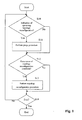
- FIG. 1 A basic embodiment for controlling the reconfiguration of a data unit network comprising bridge nodes is shown in Fig. 1 .
- the term "data unit” is used generically for describing any subdivision of data to be sent into portions, and such data units have different names depending on the protocol and the technical context, such as packet, frame, cell, protocol data unit, segment, etc.
- the term “data unit” is intended to describe any such subdivision of sending data.
- a network control procedure as shown in Fig. 1 can be conducted.
- a step S10 it is determined whether an indication of an upcoming topology reconfiguration is present.
- Conditions for a topology reconfiguration can e.g. be failure (such as a hardware or software failure of a node, or communication disruption of an interconnecting transport system) of a component (a component can be a single node or a group of nodes, with or without interconnecting transport systems, up to an entire network part) of the data unit communication network, and/or shut-down of a component of the data unit communication network.
- failure such as a hardware or software failure of a node, or communication disruption of an interconnecting transport system
- a component can be a single node or a group of nodes, with or without interconnecting transport systems, up to an entire network part
- shut-down of a component of the data unit communication network e.g. be failure (such as a hardware or software failure of a node, or communication disruption of an interconnecting transport system) of a component (a component can be a single node or a group of nodes, with or without interconnecting transport systems, up to an entire network part) of the
- an indication of an upcoming topology reconfiguration of the data unit communication network can be one or more of: signal quality degradation, a a maintenance indication, and a system update indication.
- An example of a signal quality degradation as an indication for an upcoming topology change can be the observation of the signal-to-noise ratio (SNR) on a link that is prone to interruptions due to periodic interferences, e.g. observing the SNR on a wireless link in order to conclude that when the SNR falls below a certain threshold, some form of fading is occurring (e.g. rain fading) and that a complete disconnection (i.e.
- SNR signal-to-noise ratio
- a maintenance indication can e.g. be a message from a central control entity that a node is going to be serviced. The maintenance indication may also be input at a node by service engineer.
- an update indication for informing of an upcoming software update in a bridge node or a transport system can be a message provided by a central control entity or by a maintenance engineer at the update location.
- step S10 If the outcome of step S10 is "YES", then a dedicated purge procedure S11 is conducted for purging the records of at least those nodes that will be affected by the upcoming topology change.
- the purging can consist in the complete deletion of all entries pertaining to an association of data unit address information and port identification information for all ports in the affected bridge nodes, or it can be more limited, e.g. only deleting the entries of affected ports.
- the bridge nodes involved continue to handle data units, i.e. they do not cease to operate as data unit routers and filters. This can be accomplished e.g. by letting the bridge nodes handle data units like in a default mode in which no record is available.
- a default mode is e.g. a flooding mode, i.e. a mode in which received data units are simply sent to all ports of the bridge node.
- a flooding mode i.e. a mode in which received data units are simply sent to all ports of the bridge node.
- Such a default mode is not as efficient as operating with a well established record or data base that associates port identification information with data unit address information, it is better than no operation at all. The difference in effectiveness will also depend on certain factors in the network, i.e. the momentary traffic load.
- step S10 determines whether a topology reconfiguration condition is present, e.g. one of the above mentioned conditions. If the outcome is "YES”, then a topology reconfiguration procedure S13 for the network is conducted. If the outcome is "NO” then step S13 is skipped. The procedure continues until an exit step S14 is conducted.
- a topology reconfiguration condition e.g. one of the above mentioned conditions. If the outcome is "YES”, then a topology reconfiguration procedure S13 for the network is conducted. If the outcome is "NO” then step S13 is skipped. The procedure continues until an exit step S14 is conducted.
- the procedure S13 can be done as is known from the prior art.
- the process of topology change and convergence to a new topology requires stopping the routing and filtering operation of the bridge nodes.
- the procedure S13 may or may not comprise a step of purging the records of the affected bridge nodes at the end. If a possibility for omitting a purging or flushing step at the end of the reconfiguration procedure S13 is desired, then it should be conditional on whether or not the dedicated flushing procedure S11 was previously performed. If S11 was performed, then the purging step in procedure S13 may be omitted, but if no dedicated purging S11 occurred previously, then a purging step should be executed at the end of S13.
- topology reconfiguration condition in S12 does not necessarily mean that an indication of an upcoming topology change was detected in step S10.
- topology reconfiguration conditions that can not be foreseen, e.g. in a protection case after hardware defects.
- control signalling for controlling the individual affected bridge nodes can be done in any suitable and desirable way. For example, it can be accomplished by a central control entity that communicates with all of the bridge nodes of the network. The control can also be accomplished with the help of one or more topology control protocols, where each of the bridge nodes implements the protocol(s) and runs one or more instances. These topology control protocols use dedicated control data units. Examples of such protocol are STP (Spanning Tree Protocol), RSTP (Rapid Spanning Tree Protocol) and MSPT (Multiple Spanning Tree Protocol) known from the IEEE 802 standard family. These protocols use so-called BPDUs (Bridge Protocol Data Units) as dedicated control data units. Examples of systems using a control protocol will be discussed further on with reference to Figures 7 and 8 .
- the present invention achieves the advantage of potentially reducing the purge time in the reconfiguration procedure S13, because even if such a purge time is still present in S13, it is typically much shorter than in prior art situations, because the records in the affected bridge nodes have already been purged previously in the dedicated purge procedure S11.
- the records or data bases can be quite extensive, such that the process of deleting can take several seconds for each record. Therefore, the concept of the invention provides the effect of enabling a reduction of the total recovery time.
- Such a learning procedure can also be conducted as a part of the designated purge procedure (S11) of the present invention. It is noted that the associations that will be learned during the designated purge procedure will generally not be useful for the future, due to the expected reconfiguration. But as long as the topology reconfiguration procedure (S13) comprises its own purge step at the end, the newly recorded association during the dedicated purge procedure will be deleted after reconfiguration. The effects of the present concept can still be achieved, because the amount of data built up in the records or data bases of the bridge nodes during such a learning procedure in the dedicated purge procedure will generally be small, such that the process of deletion at the end of the topology reconfiguration procedure will still be very quick compared to the deletion of a record that was built up over a long period of time.
- the dedicated purge procedure comprises disabling the learning state for one or more of the ports of the bridge nodes.
- the dedicated purge procedure comprises disabling the learning state for one or more of the ports of the bridge nodes.
- the topology reconfiguration procedure may comprise a step of enabling the learning state after reconfiguration for those ports of the bridge nodes that had the learning state disabled during the dedicated purge procedure.
- each bridge node may be controlled to set the learning state of its ports back to "on" after the final purge step P shown in the figure at the bottom.
- the entire control procedure may comprise a step of enabling said learning state for ports of said bridge nodes whose learning state had been disabled upon expiration of a timer.
- the timer may be triggered in any suitable way, e.g. when the disablement of the learning state occurs, or when the purging begins, or when then purging ends.
- Fig. 3 shows a loop arrangement of bridge nodes which could be a complete network or a part of a larger network, as explained previously.
- the topology control protocol e.g. STP, RSTP, MSTP
- STP Secure Transfer Protocol
- RSTP RSTP
- MSTP Mobile Broadband Protocol
- this is a logical block designated by the protocol operation, in order to avoid a topological loop.
- the lower port of node 35 is logically blocked in order to avoid loop traffic in the physical loop structure.
- L1 to L7 represent transport systems that are bridged by the bridge nodes 31 to 37.
- L1 to L7 can be proper networks themselves, such as LANs.
- the transport systems are nor shown in Fig. 3 for simplicity. It is noted that the concept of the invention is particularly well applicable when the transport systems are point-to-point LANs.
- Fig. 6 shows a topology reconfiguration procedure according to the prior art, as it would e.g. be performed by instances of one of the above mentioned protocols STP, RSTP or MSTP.
- Bridge nodes 31 and 32 detect a shut-off of transport system L1 (e.g. a LAN) that connects these nodes, see disruption 601. As a consequence, nodes 31 and 32 purge their records or data bases (see P in the Figure) and node 32 initiates the reconfiguration procedure for the affected network nodes.
- L1 e.g. a LAN
- the double line arrows signify special control messages that carry an indicator of a topology change.
- purging symbol on the left-hand side of a line symbolizes the purging of the record with respect to entries relating to the port on the left-hand side of the respective bridge node
- topology convergence time A extends from the detection of the disruption 601 to the arrival of the control message at node 31 that was sent by node 37.
- the purging of all records requires the additional period B, such that the total recovery time is A+B.
- FIG. 7 shows a first embodiment of the present invention, in which each bridge node runs a first and a second instance of the topology control protocol in parallel.
- the first instance is arranged to conduct steps for the topology reconfiguration procedure in each respective bridge node and the second instance is arranged to conduct steps for the purge procedure in each respective bridge node.
- nodes 31 and 32 receive an indication 700 of the upcoming shut-down of transport system L1 in a predetermined number of second, e.g. a maintenance message.
- the nodes are running a second instance of the topology control protocol, which second instances conduct the purge procedure described as S11 in connection with Fig. 1 .
- the topology reconfiguration procedure (S13 in Fig. 1 ) is like in Fig. 6 , such that no further explanation is necessary.
- the appropriate control messages are sent.
- the second instances can be arranged to mimic the action of the first instances, except for the actual reconfiguration.
- the second instances can perform a similar signalling in response to the indication 700 as the first instances perform in response to disturbance 601, but the second instances do not reconfigure the topology.
- the control messages sent according to the topology control protocol can contain markers or flags that allow distinguishing between the different instances. For example, the MSTP can distinguish up to 64 instances.
- the second instances perform a purging P of the records in the affected nodes. Consequently, when later the purging P is conducted in the topology reconfiguration procedure by the first instances, this purging is very quick, as the records had already been purged previously. Consequently, there is virtually no supplementary time B and the total recovery time is determined by A, i.e. shorter than in the example of Fig. 6 .
- Fig. 8 shows another example, which can be conducted alternatively or together with the functionality described in connection with Fig. 7 .
- the indication 700 leads to a cascade of simple control messages that contain a special marking or flag that informs the receiver to purge its record with respect to the port at which the control message arrived and to send a corresponding control message out of its other ports.
- the dedicated purge procedure ends when the enacting nodes 31 and 32 receive this type of control message back from the neighbouring nodes. In this example, no second instance of the topology control protocol is necessary.
- the purging time at the end of the topology reconfiguration procedure is short, such that the total recovery time is shorter than in the case of Fig. 6 .
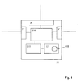
- Figure 5 shows a schematic example of a bridge node 51 according to an embodiment of the invention. It comprises ports P, a data unit buffer 510, a controller 511, such as a processor, and a memory 512, which comprises a record 5120.
- the record can comprise a filtering data base (FDB) as known from IEEE 802.1.
- the record 5120 is for associating data unit address information with port identification information.
- the controller 511 is for controlling the bridge node and processing of received data units, and is capable of querying the record 5120 for determining which of the ports P to forward a received data unit to.
- the bridge node 51 is arranged to initiate the previously described topology reconfiguration procedure for the data unit communication network when detecting an occurrence of any one of one or more topology reconfiguration conditions, and it is furthermore arranged to initiate the previously described dedicated purge procedure of the records of said bridge nodes when detecting an occurrence of an indication of an upcoming topology reconfiguration of said data unit communication network, and to continue handling data units during said purge procedure.
- the initiating of the procedure can be done in any suitable or desirable way, e.g. by notifying a central control entity or by sending out appropriate control messages as regulated by a topology control protocol, see the examples of nodes 31 and 32 in Figures 7 and 8 .
- Fig. 4 shows a flow chart of a method for controlling a bridge node such as node 51.
- step S40 it is determined whether an indication of an upcoming topology reconfiguration is present. If so (YES), then the dedicated purge procedure is initiated, see step S41. If no indication is present (NO at S40), the procedure passes to step S42, in which it is determined whether a topology reconfiguration condition is present. If such a condition is present (YES), then the topology reconfiguration procedure is initiated, otherwise (NO at S42) step S43 is skipped. The procedure continues until an exit step S44 is conducted.
- the just described method of controlling a bridge node can also be embodied as a computer program comprising computer program parts arranged to conduct this method when loaded and executed on a programmable bridge node for a data unit communication network.
- the controller 511 shown in Fig. 5 can be a programmable processor.
- the invention can also be embodied as a computer program product comprising such a computer program, e.g. a data carrier comprising the program.
- a computer program comprising computer program parts arranged to conduct the method of one of claims 9 to 15 when loaded and executed on a programmable bridge node such as e.g. node 51 for a data unit communication network is disclosed.
- a computer program product comprising said aforementioned computer program may be further disclosed.
Landscapes
- Engineering & Computer Science (AREA)
- Computer Networks & Wireless Communication (AREA)
- Signal Processing (AREA)
- Data Exchanges In Wide-Area Networks (AREA)
Claims (17)
- Verfahren zum Umkonfigurieren eines Dateneinheitskommunikationsnetzes, das Brückenknoten (51) umfasst, wobei jeder Brückenknoten (51) umfasst:- zwei oder mehr Anschlüsse zum Empfangen und Senden von Dateneinheiten,- eine Steuerung (511) zum Steuern des Brückenknotens (51) und zum Verarbeiten von empfangenen Dateneinheiten, und- einen Datensatz (5120) zum Assoziieren von Dateneinheitsadressinformationen mit Anschlussidentifikationsinformationen, wobei die Steuerung (511) zum Abfragen des Datensatzes (5120) in der Lage ist, um zu bestimmen, an welchen einen oder welche mehrere Anschlüsse (P) eine empfangene Dateneinheit weitergeleitet werden soll,
wobei das Verfahren umfasst:- Durchführen einer Topologieumkonfigurationsprozedur (S13) für das Dateneinheitskommunikationsnetz bei Erkennen eines Auftretens einer beliebigen von einer oder mehreren Topologieumkonfigurationsbedingungen,
gekennzeichnet durch:- Durchführen einer Bereinigungsprozedur (S11) der Datensätze der Brückenknoten (51) bei Erkennen eines Auftretens einer Anzeige einer bevorstehenden Topologieumkonfiguration des Dateneinheitskommunikationsnetzes, wobei die Anzeige von allen der Topologieumkonfigurationsbedingungen verschieden ist, und Fortfahren mit der Verarbeitung der Dateneinheiten in den Brückenknoten (51) während der Bereinigungsprozedur. - Verfahren nach Anspruch 1, wobei jeder Brückenknoten (51) so steuerbar ist, dass er mindestens einen seiner Anschlüsse (P) mit einem Lernzustand assoziiert, gemäß dem der Datensatz (5120) des Brückenknotens auf der Basis von Informationen aktualisiert wird, die in Dateneinheiten enthalten sind, die an einem Anschluss (P) empfangen werden, der mit dem Lernzustand assoziiert ist, wobei die Bereinigungsprozedur ein Deaktivieren des Lernzustands für einen oder mehrere der Anschlüsse (P) der Brückenknoten (51) umfasst.
- Verfahren nach Anspruch 2, wobei die Topologieumkonfigurationsprozedur einen Schritt des Aktivierens des Lernzustands für den einen oder die mehreren der Anschlüsse (P) der Brückenknoten (51) nach der Umkonfiguration umfasst.
- Verfahren nach Anspruch 2, wobei die Topologieumkonfigurationsprozedur einen Schritt des Aktivierens des Lernzustands für den einen oder die mehreren der Anschlüsse (P) der Brückenknoten (51) nach Ablauf eines Zeitgebers umfasst.
- Verfahren nach einem der vorhergehenden Anschlüsse, wobei die Brückenknoten (51) ein Topologiesteuerungsprotokoll implementieren, das assoziierte Topologiesteuerungsdateneinheiten zur Signalisierung zwischen den Brückenknoten (51) verwendet.
- Verfahren nach Anspruch 5, wobei jeder Brückenknoten (51) eine erste und eine zweite Instanz des Topologiesteuerungsprotokolls parallel ausführt, wobei die erste Instanz so ausgelegt ist, dass sie Schritte für die Topologieumkonfigurationsprozedur in jedem entsprechenden Brückenknoten (51) ausführt, und die zweite Instanz so ausgelegt ist, dass sie Schritte für die Bereinigungsprozedur in jedem entsprechenden Brückenknoten (51) ausführt.
- Verfahren nach Anspruch 5 oder 6, wobei die Bereinigungsprozedur ein Senden von dedizierten Topologiesteuerungsdateneinheiten umfasst, die eine Bereinigungsbenachrichtigung an die Brückenknoten (51) umfassen.
- Verfahren nach einem der vorhergehenden Ansprüche, wobei das Verfahren mindestens eines von Folgendem umfasst:- die eine oder die mehreren Topologieumkonfigurationsbedingungen umfassen einen Ausfall einer Komponente des Dateneinheitskommunikationsnetzes,- die eine oder die mehreren Topologieumkonfigurationsbedingungen umfassen eine Abschaltung einer Komponente des Dateneinheitskommunikationsnetzes,- die Anzeige einer bevorstehenden Topologieumkonfiguration des Dateneinheitskommunikationsnetzes umfasst eine Verschlechterung der Signalqualität,- die Anzeige einer bevorstehenden Topologieumkonfiguration des Dateneinheitskommunikationsnetzes umfasst eine Wartungsanzeige,- die Anzeige einer bevorstehenden
Topologieumkonfiguration des Dateneinheitskommunikationsnetzes umfasst eine Systemaktualisierungsanzeige,- die Brückenknoten (51) sind Medienzugriffssteuerungsknoten, die sich auf der OSI-Schicht 2 befinden, die lokale Netzwerke miteinander verbindet. - Verfahren zur Steuerung eines Brückenknotens (51) für ein Dateneinheitskommunikationsnetz, wobei der Brückenknoten (51) umfasst:- zwei oder mehr Anschlüsse (P) zum Empfangen und Senden von Dateneinheiten,- eine Steuerung (511) zum Steuern des Brückenknotens (51) und zum Verarbeiten von empfangenen Dateneinheiten, und- einen Datensatz (5120) zum Assoziieren von Dateneinheitsadressinformationen mit Anschlussidentifikationsinformationen, wobei die Steuerung 511) zum Abfragen des Datensatzes (5120) in der Lage ist, um zu bestimmen, an welchen einen oder welche mehrere Anschlüsse (P) eine Dateneinheit weiterleitet werden soll, wobei das Verfahren umfasst:- Einleiten (S43) einer Topologieumkonfigurationsprozedur für das Dateneinheitskommunikationsnetz bei Erkennen eines Auftretens einer beliebigen von einer oder mehreren Topologieumkonfigurationsbedingungen,
gekennzeichnet durch:- Einleiten (S41) einer Bereinigungsprozedur der Datensätze der Brückenknoten (51) im Dateneinheitskommunikationsnetz bei Erkennen eines Auftretens einer Anzeige einer bevorstehenden Topologieumkonfiguration des Dateneinheitskommunikationsnetzes, wobei die Anzeige von allen der Topologieumkonfigurationsbedingungen verschieden ist, und Fortfahren mit der Verarbeitung von Dateneinheiten während der Bereinigungsprozedur. - Verfahren nach Anspruch 9, wobei der Brückenknoten (51) so steuerbar ist, dass er mindestens einen seiner Anschlüsse (P) mit einem Lernzustand assoziiert, gemäß dem der Datensatz (5120) des Brückenknotens auf der Basis von Informationen aktualisiert wird, die in Dateneinheiten enthalten sind, die an einem Port (P) empfangen werden, der mit dem Lernzustand assoziiert ist, wobei die Bereinigungsprozedur ein Deaktivieren des Lernzustands für einen oder mehrere der Anschlüsse (P) der Brückenknoten (51) umfasst.
- Verfahren nach Anspruch 10, wobei der Brückenknoten (51) den Lernzustand für den einen oder die mehreren Anschlüsse (P) nach der Umkonfiguration aktiviert.
- Verfahren nach Anspruch 10 oder 11, wobei der Brückenknoten (51) den Lernzustand für den einen oder die mehreren Anschlüsse (P) nach Ablauf eines Zeitgebers aktiviert.
- Verfahren nach einem der Ansprüche 9 bis 12,
wobei der Brückenknoten (51) ein Topologiesteuerungsprotokoll implementiert, das assoziierte Topologiesteuerungsdateneinheiten zur Signalisierung zwischen den Brückenknoten des Dateneinheitskommunikationsnetzes verwendet. - Verfahren nach Anspruch 13, wobei jeder Brückenknoten (51) eine erste und eine zweite Instanz des Topologiesteuerungsprotokolls parallel ausführt, wobei die erste Instanz so ausgelegt ist, dass sie Schritte für die Topologieumkonfigurationsprozedur ausführt, und die zweite Instanz so ausgelegt ist, dass sie Schritte für die Bereinigungsprozedur ausführt.
- Verfahren nach Anspruch 13 oder 14, wobei der Brückenknoten (51) dedizierte Topologiesteuerungsdateneinheiten sendet, die eine Bereinigungsbenachrichtigung an andere Brückenknoten des Dateneinheitskommunikationsnetzes umfassen.
- Brückenknoten (51) für ein Dateneinheitskommunikationsnetz, wobei der Brückenknoten (51) umfasst:- zwei oder mehr Anschlüsse (P) zum Empfangen und Senden von Dateneinheiten,- eine Steuerung (511) zum Steuern des Brückenknotens (51) und zum Verarbeiten von empfangenen Dateneinheiten, und- einen Datensatz (5120) zum Assoziieren von Dateneinheitsadressinformationen mit Anschlussidentifikationsinformationen, wobei die Steuerung (511) zum Abfragen des Datensatzes (5120) in der Lage ist, um zu bestimmen, an welchen einen oder welche mehrere Anschlüsse (P) eine empfangene Dateneinheit weitergeleitet werden soll, und der Brückenknoten (51) so ausgelegt ist, dass er bei Erkennen eines Auftretens einer beliebigen von einer oder mehreren Topologieumkonfigurationsbedingungen eine Topologieumkonfigurationsprozedur für das Dateneinheitskommunikationsnetz einleitet,
dadurch gekennzeichnet, dass
der Brückenknoten (51) außerdem so ausgelegt ist, dass er bei Erkennen eines Auftretens einer Anzeige einer bevorstehenden Topologieumkonfiguration des Dateneinheitskommunikationsnetzes eine Bereinigungsprozedur der Datensätze der Brückenknoten (51) einleitet, wobei die Anzeige von allen der Topologieumkonfigurationsbedingungen verschieden ist, und mit der Verarbeitung von Dateneinheiten während der Bereinigungsprozedur fortfährt. - Brückenknoten nach Anspruch 16, der so ausgelegt ist, dass er das Verfahren nach einem der Ansprüche 10 bis 15 ausführt.
Applications Claiming Priority (1)
| Application Number | Priority Date | Filing Date | Title |
|---|---|---|---|
| PCT/EP2007/058403 WO2009021554A1 (en) | 2007-08-14 | 2007-08-14 | Network reconfiguration method |
Publications (2)
| Publication Number | Publication Date |
|---|---|
| EP2183885A1 EP2183885A1 (de) | 2010-05-12 |
| EP2183885B1 true EP2183885B1 (de) | 2012-06-06 |
Family
ID=39473349
Family Applications (1)
| Application Number | Title | Priority Date | Filing Date |
|---|---|---|---|
| EP07802598A Not-in-force EP2183885B1 (de) | 2007-08-14 | 2007-08-14 | Netzwerkumkonfigurationsverfahren |
Country Status (3)
| Country | Link |
|---|---|
| US (1) | US8743741B2 (de) |
| EP (1) | EP2183885B1 (de) |
| WO (1) | WO2009021554A1 (de) |
Families Citing this family (4)
| Publication number | Priority date | Publication date | Assignee | Title |
|---|---|---|---|---|
| US8159936B2 (en) | 2009-03-31 | 2012-04-17 | Extreme Networks, Inc. | Network convergence in response to a topology change |
| US9383989B1 (en) | 2014-06-16 | 2016-07-05 | Symantec Corporation | Systems and methods for updating applications |
| CN113158557B (zh) * | 2021-03-31 | 2024-06-07 | 清华大学 | 二元度特性网络重构方法、装置、设备及存储介质 |
| CN117255007B (zh) * | 2022-03-28 | 2025-12-16 | 安科讯(福建)科技有限公司 | 一种变电所无线网桥的故障恢复方法及终端 |
Family Cites Families (10)
| Publication number | Priority date | Publication date | Assignee | Title |
|---|---|---|---|---|
| US5790808A (en) * | 1995-07-06 | 1998-08-04 | 3 Com | Active topology maintenance in reconfiguring bridged local area networks with state transition with forgetting interval |
| US6330229B1 (en) * | 1998-11-09 | 2001-12-11 | 3Com Corporation | Spanning tree with rapid forwarding database updates |
| JP4021841B2 (ja) * | 2003-10-29 | 2007-12-12 | 富士通株式会社 | スパニングツリープロトコルにおける制御パケット処理装置および方法 |
| US6717922B2 (en) * | 2002-03-04 | 2004-04-06 | Foundry Networks, Inc. | Network configuration protocol and method for rapid traffic recovery and loop avoidance in ring topologies |
| US7379429B1 (en) * | 2002-12-20 | 2008-05-27 | Foundry Networks, Inc. | Optimizations and enhancements to the IEEE RSTP 802.1w implementation |
| NO318311B1 (no) * | 2003-02-04 | 2005-02-28 | Ontime Networks As | Fremgangsmate og apparat for rask rekonfigurering av en nettverkstopologi |
| WO2006065795A2 (en) | 2004-12-14 | 2006-06-22 | Alcatel Lucent | Ring rapid spanning tree protocol |
| US7564779B2 (en) * | 2005-07-07 | 2009-07-21 | Alcatel Lucent | Ring rapid spanning tree protocol |
| US7804778B1 (en) * | 2005-11-30 | 2010-09-28 | At&T Intellectual Property Ii, L.P. | Method and apparatus for monitoring link diversity |
| US7903586B2 (en) * | 2006-11-01 | 2011-03-08 | Alcatel Lucent | Ring rapid multiple spanning tree protocol system and method |
-
2007
- 2007-08-14 US US12/673,544 patent/US8743741B2/en not_active Expired - Fee Related
- 2007-08-14 WO PCT/EP2007/058403 patent/WO2009021554A1/en not_active Ceased
- 2007-08-14 EP EP07802598A patent/EP2183885B1/de not_active Not-in-force
Also Published As
| Publication number | Publication date |
|---|---|
| US8743741B2 (en) | 2014-06-03 |
| WO2009021554A1 (en) | 2009-02-19 |
| EP2183885A1 (de) | 2010-05-12 |
| US20130194972A1 (en) | 2013-08-01 |
Similar Documents
| Publication | Publication Date | Title |
|---|---|---|
| US8699380B2 (en) | Port table flushing in ethernet networks | |
| US7518988B2 (en) | Ring switchover method | |
| US6717922B2 (en) | Network configuration protocol and method for rapid traffic recovery and loop avoidance in ring topologies | |
| US7564779B2 (en) | Ring rapid spanning tree protocol | |
| CN102045229B (zh) | 一种以太多环网的拓扑管理方法和系统 | |
| EP2178251B1 (de) | Verfahren, Vorrichtung und System zum Ringschutz | |
| US8654673B2 (en) | Configuring networks including spanning trees | |
| US6697339B1 (en) | High availability spanning tree with rapid reconfiguration with alternate port selection | |
| CN101232428B (zh) | 一种以太网环保护方法及装置 | |
| US8203932B2 (en) | Method and system for protection switching in ethernet ring | |
| EP1768319A1 (de) | Verfahren zur Redundanzbereitstellung in Brücken zwischen RPR-Ringen | |
| EP1469639B1 (de) | Verfahren, Softwareprodukt, Speichermedium und Ethernetswitch zur Verbesserung des STP Protokolls in VLAN Ethernet Netzwerken | |
| CN101252503B (zh) | 环网的业务倒换方法和装置 | |
| US7821920B2 (en) | Flushing processing unit and method of switching device in network using spanning tree protocol | |
| EP2020782A1 (de) | Verfahren und Vorrichtung zum Schutz eines Ringes und System mit einer derartigen Vorrichtung | |
| US8743741B2 (en) | Network reconfiguration method | |
| US20030161275A1 (en) | Spanning tree method | |
| EP1672847B1 (de) | Ring Rapid Spanning Tree Protokoll | |
| EP2479942B1 (de) | Verfahren und system zur erkennung von ringnetzwerk-schutzinformationen | |
| AU2012390581B2 (en) | Method for running a computer network | |
| US11025527B2 (en) | Topology change processing in bridged networks using a spanning tree protocol | |
| JP2010283679A (ja) | レイヤ2ノード冗長システムと方法 | |
| JP2015136079A (ja) | 通信ノード装置及びネットワークシステム |
Legal Events
| Date | Code | Title | Description |
|---|---|---|---|
| PUAI | Public reference made under article 153(3) epc to a published international application that has entered the european phase |
Free format text: ORIGINAL CODE: 0009012 |
|
| 17P | Request for examination filed |
Effective date: 20100305 |
|
| AK | Designated contracting states |
Kind code of ref document: A1 Designated state(s): AT BE BG CH CY CZ DE DK EE ES FI FR GB GR HU IE IS IT LI LT LU LV MC MT NL PL PT RO SE SI SK TR |
|
| AX | Request for extension of the european patent |
Extension state: AL BA HR MK RS |
|
| RIN1 | Information on inventor provided before grant (corrected) |
Inventor name: THE OTHER INVENTORS HAVE AGREED TO WAIVE THEIR ENT Inventor name: ALBERTY, THOMAS Inventor name: LEUWER, HERBERT Inventor name: KAISER, THORSTEN |
|
| 17Q | First examination report despatched |
Effective date: 20101004 |
|
| DAX | Request for extension of the european patent (deleted) | ||
| GRAP | Despatch of communication of intention to grant a patent |
Free format text: ORIGINAL CODE: EPIDOSNIGR1 |
|
| GRAS | Grant fee paid |
Free format text: ORIGINAL CODE: EPIDOSNIGR3 |
|
| GRAA | (expected) grant |
Free format text: ORIGINAL CODE: 0009210 |
|
| AK | Designated contracting states |
Kind code of ref document: B1 Designated state(s): AT BE BG CH CY CZ DE DK EE ES FI FR GB GR HU IE IS IT LI LT LU LV MC MT NL PL PT RO SE SI SK TR |
|
| REG | Reference to a national code |
Ref country code: GB Ref legal event code: FG4D |
|
| REG | Reference to a national code |
Ref country code: AT Ref legal event code: REF Ref document number: 561470 Country of ref document: AT Kind code of ref document: T Effective date: 20120615 Ref country code: CH Ref legal event code: EP |
|
| REG | Reference to a national code |
Ref country code: IE Ref legal event code: FG4D |
|
| REG | Reference to a national code |
Ref country code: DE Ref legal event code: R096 Ref document number: 602007023191 Country of ref document: DE Effective date: 20120802 |
|
| REG | Reference to a national code |
Ref country code: NL Ref legal event code: VDEP Effective date: 20120606 |
|
| PG25 | Lapsed in a contracting state [announced via postgrant information from national office to epo] |
Ref country code: LT Free format text: LAPSE BECAUSE OF FAILURE TO SUBMIT A TRANSLATION OF THE DESCRIPTION OR TO PAY THE FEE WITHIN THE PRESCRIBED TIME-LIMIT Effective date: 20120606 Ref country code: FI Free format text: LAPSE BECAUSE OF FAILURE TO SUBMIT A TRANSLATION OF THE DESCRIPTION OR TO PAY THE FEE WITHIN THE PRESCRIBED TIME-LIMIT Effective date: 20120606 Ref country code: SE Free format text: LAPSE BECAUSE OF FAILURE TO SUBMIT A TRANSLATION OF THE DESCRIPTION OR TO PAY THE FEE WITHIN THE PRESCRIBED TIME-LIMIT Effective date: 20120606 Ref country code: CY Free format text: LAPSE BECAUSE OF FAILURE TO SUBMIT A TRANSLATION OF THE DESCRIPTION OR TO PAY THE FEE WITHIN THE PRESCRIBED TIME-LIMIT Effective date: 20120606 |
|
| REG | Reference to a national code |
Ref country code: AT Ref legal event code: MK05 Ref document number: 561470 Country of ref document: AT Kind code of ref document: T Effective date: 20120606 |
|
| REG | Reference to a national code |
Ref country code: LT Ref legal event code: MG4D Effective date: 20120606 |
|
| PG25 | Lapsed in a contracting state [announced via postgrant information from national office to epo] |
Ref country code: LV Free format text: LAPSE BECAUSE OF FAILURE TO SUBMIT A TRANSLATION OF THE DESCRIPTION OR TO PAY THE FEE WITHIN THE PRESCRIBED TIME-LIMIT Effective date: 20120606 Ref country code: SI Free format text: LAPSE BECAUSE OF FAILURE TO SUBMIT A TRANSLATION OF THE DESCRIPTION OR TO PAY THE FEE WITHIN THE PRESCRIBED TIME-LIMIT Effective date: 20120606 |
|
| PG25 | Lapsed in a contracting state [announced via postgrant information from national office to epo] |
Ref country code: SK Free format text: LAPSE BECAUSE OF FAILURE TO SUBMIT A TRANSLATION OF THE DESCRIPTION OR TO PAY THE FEE WITHIN THE PRESCRIBED TIME-LIMIT Effective date: 20120606 Ref country code: CZ Free format text: LAPSE BECAUSE OF FAILURE TO SUBMIT A TRANSLATION OF THE DESCRIPTION OR TO PAY THE FEE WITHIN THE PRESCRIBED TIME-LIMIT Effective date: 20120606 Ref country code: BE Free format text: LAPSE BECAUSE OF FAILURE TO SUBMIT A TRANSLATION OF THE DESCRIPTION OR TO PAY THE FEE WITHIN THE PRESCRIBED TIME-LIMIT Effective date: 20120606 Ref country code: AT Free format text: LAPSE BECAUSE OF FAILURE TO SUBMIT A TRANSLATION OF THE DESCRIPTION OR TO PAY THE FEE WITHIN THE PRESCRIBED TIME-LIMIT Effective date: 20120606 Ref country code: EE Free format text: LAPSE BECAUSE OF FAILURE TO SUBMIT A TRANSLATION OF THE DESCRIPTION OR TO PAY THE FEE WITHIN THE PRESCRIBED TIME-LIMIT Effective date: 20120606 Ref country code: RO Free format text: LAPSE BECAUSE OF FAILURE TO SUBMIT A TRANSLATION OF THE DESCRIPTION OR TO PAY THE FEE WITHIN THE PRESCRIBED TIME-LIMIT Effective date: 20120606 Ref country code: IS Free format text: LAPSE BECAUSE OF FAILURE TO SUBMIT A TRANSLATION OF THE DESCRIPTION OR TO PAY THE FEE WITHIN THE PRESCRIBED TIME-LIMIT Effective date: 20121006 Ref country code: NL Free format text: LAPSE BECAUSE OF FAILURE TO SUBMIT A TRANSLATION OF THE DESCRIPTION OR TO PAY THE FEE WITHIN THE PRESCRIBED TIME-LIMIT Effective date: 20120606 |
|
| PG25 | Lapsed in a contracting state [announced via postgrant information from national office to epo] |
Ref country code: PT Free format text: LAPSE BECAUSE OF FAILURE TO SUBMIT A TRANSLATION OF THE DESCRIPTION OR TO PAY THE FEE WITHIN THE PRESCRIBED TIME-LIMIT Effective date: 20121008 Ref country code: PL Free format text: LAPSE BECAUSE OF FAILURE TO SUBMIT A TRANSLATION OF THE DESCRIPTION OR TO PAY THE FEE WITHIN THE PRESCRIBED TIME-LIMIT Effective date: 20120606 Ref country code: IT Free format text: LAPSE BECAUSE OF FAILURE TO SUBMIT A TRANSLATION OF THE DESCRIPTION OR TO PAY THE FEE WITHIN THE PRESCRIBED TIME-LIMIT Effective date: 20120606 |
|
| REG | Reference to a national code |
Ref country code: CH Ref legal event code: PL |
|
| PG25 | Lapsed in a contracting state [announced via postgrant information from national office to epo] |
Ref country code: MC Free format text: LAPSE BECAUSE OF NON-PAYMENT OF DUE FEES Effective date: 20120831 |
|
| PLBE | No opposition filed within time limit |
Free format text: ORIGINAL CODE: 0009261 |
|
| STAA | Information on the status of an ep patent application or granted ep patent |
Free format text: STATUS: NO OPPOSITION FILED WITHIN TIME LIMIT |
|
| PG25 | Lapsed in a contracting state [announced via postgrant information from national office to epo] |
Ref country code: CH Free format text: LAPSE BECAUSE OF NON-PAYMENT OF DUE FEES Effective date: 20120831 Ref country code: LI Free format text: LAPSE BECAUSE OF NON-PAYMENT OF DUE FEES Effective date: 20120831 Ref country code: DK Free format text: LAPSE BECAUSE OF FAILURE TO SUBMIT A TRANSLATION OF THE DESCRIPTION OR TO PAY THE FEE WITHIN THE PRESCRIBED TIME-LIMIT Effective date: 20120606 Ref country code: ES Free format text: LAPSE BECAUSE OF FAILURE TO SUBMIT A TRANSLATION OF THE DESCRIPTION OR TO PAY THE FEE WITHIN THE PRESCRIBED TIME-LIMIT Effective date: 20120917 |
|
| 26N | No opposition filed |
Effective date: 20130307 |
|
| REG | Reference to a national code |
Ref country code: FR Ref legal event code: ST Effective date: 20130430 |
|
| REG | Reference to a national code |
Ref country code: IE Ref legal event code: MM4A |
|
| GBPC | Gb: european patent ceased through non-payment of renewal fee |
Effective date: 20120906 |
|
| REG | Reference to a national code |
Ref country code: DE Ref legal event code: R097 Ref document number: 602007023191 Country of ref document: DE Effective date: 20130307 |
|
| PG25 | Lapsed in a contracting state [announced via postgrant information from national office to epo] |
Ref country code: IE Free format text: LAPSE BECAUSE OF NON-PAYMENT OF DUE FEES Effective date: 20120814 Ref country code: BG Free format text: LAPSE BECAUSE OF FAILURE TO SUBMIT A TRANSLATION OF THE DESCRIPTION OR TO PAY THE FEE WITHIN THE PRESCRIBED TIME-LIMIT Effective date: 20120906 Ref country code: GB Free format text: LAPSE BECAUSE OF NON-PAYMENT OF DUE FEES Effective date: 20120906 |
|
| PG25 | Lapsed in a contracting state [announced via postgrant information from national office to epo] |
Ref country code: FR Free format text: LAPSE BECAUSE OF NON-PAYMENT OF DUE FEES Effective date: 20120831 |
|
| PG25 | Lapsed in a contracting state [announced via postgrant information from national office to epo] |
Ref country code: MT Free format text: LAPSE BECAUSE OF FAILURE TO SUBMIT A TRANSLATION OF THE DESCRIPTION OR TO PAY THE FEE WITHIN THE PRESCRIBED TIME-LIMIT Effective date: 20120606 |
|
| PG25 | Lapsed in a contracting state [announced via postgrant information from national office to epo] |
Ref country code: TR Free format text: LAPSE BECAUSE OF FAILURE TO SUBMIT A TRANSLATION OF THE DESCRIPTION OR TO PAY THE FEE WITHIN THE PRESCRIBED TIME-LIMIT Effective date: 20120606 |
|
| PG25 | Lapsed in a contracting state [announced via postgrant information from national office to epo] |
Ref country code: LU Free format text: LAPSE BECAUSE OF NON-PAYMENT OF DUE FEES Effective date: 20120814 |
|
| PG25 | Lapsed in a contracting state [announced via postgrant information from national office to epo] |
Ref country code: HU Free format text: LAPSE BECAUSE OF FAILURE TO SUBMIT A TRANSLATION OF THE DESCRIPTION OR TO PAY THE FEE WITHIN THE PRESCRIBED TIME-LIMIT Effective date: 20070814 |
|
| PG25 | Lapsed in a contracting state [announced via postgrant information from national office to epo] |
Ref country code: GR Free format text: LAPSE BECAUSE OF FAILURE TO SUBMIT A TRANSLATION OF THE DESCRIPTION OR TO PAY THE FEE WITHIN THE PRESCRIBED TIME-LIMIT Effective date: 20120606 |
|
| PGFP | Annual fee paid to national office [announced via postgrant information from national office to epo] |
Ref country code: DE Payment date: 20190828 Year of fee payment: 13 |
|
| REG | Reference to a national code |
Ref country code: DE Ref legal event code: R119 Ref document number: 602007023191 Country of ref document: DE |
|
| PG25 | Lapsed in a contracting state [announced via postgrant information from national office to epo] |
Ref country code: DE Free format text: LAPSE BECAUSE OF NON-PAYMENT OF DUE FEES Effective date: 20210302 |