EP2184009A2 - Stimulateur cardiaque à une chambre - Google Patents
Stimulateur cardiaque à une chambre Download PDFInfo
- Publication number
- EP2184009A2 EP2184009A2 EP09172867A EP09172867A EP2184009A2 EP 2184009 A2 EP2184009 A2 EP 2184009A2 EP 09172867 A EP09172867 A EP 09172867A EP 09172867 A EP09172867 A EP 09172867A EP 2184009 A2 EP2184009 A2 EP 2184009A2
- Authority
- EP
- European Patent Office
- Prior art keywords
- ventricular
- electrode
- detection unit
- unit
- heart
- Prior art date
- Legal status (The legal status is an assumption and is not a legal conclusion. Google has not performed a legal analysis and makes no representation as to the accuracy of the status listed.)
- Withdrawn
Links
- 230000002861 ventricular Effects 0.000 claims abstract description 113
- 238000001514 detection method Methods 0.000 claims abstract description 52
- 208000003734 Supraventricular Tachycardia Diseases 0.000 claims abstract description 36
- 230000000747 cardiac effect Effects 0.000 claims abstract description 34
- 230000009471 action Effects 0.000 claims abstract description 27
- 230000001746 atrial effect Effects 0.000 claims abstract description 20
- 208000001871 Tachycardia Diseases 0.000 claims description 36
- 230000006794 tachycardia Effects 0.000 claims description 35
- 230000035939 shock Effects 0.000 claims description 27
- 239000011159 matrix material Substances 0.000 claims description 12
- 238000012935 Averaging Methods 0.000 claims description 8
- 230000033764 rhythmic process Effects 0.000 claims description 7
- 210000002620 vena cava superior Anatomy 0.000 claims description 3
- 208000003663 ventricular fibrillation Diseases 0.000 claims description 2
- 206010047302 ventricular tachycardia Diseases 0.000 abstract description 7
- 230000000694 effects Effects 0.000 abstract description 2
- 230000000638 stimulation Effects 0.000 description 23
- 238000011156 evaluation Methods 0.000 description 7
- 210000002837 heart atrium Anatomy 0.000 description 5
- 210000005242 cardiac chamber Anatomy 0.000 description 4
- 230000034225 regulation of ventricular cardiomyocyte membrane depolarization Effects 0.000 description 3
- 238000012360 testing method Methods 0.000 description 3
- 206010003658 Atrial Fibrillation Diseases 0.000 description 2
- 206010003668 atrial tachycardia Diseases 0.000 description 2
- 238000010586 diagram Methods 0.000 description 2
- 230000002349 favourable effect Effects 0.000 description 2
- 230000006872 improvement Effects 0.000 description 2
- 238000001615 p wave Methods 0.000 description 2
- 230000035945 sensitivity Effects 0.000 description 2
- 230000000213 tachycardiac effect Effects 0.000 description 2
- 230000007704 transition Effects 0.000 description 2
- 206010015856 Extrasystoles Diseases 0.000 description 1
- 208000000418 Premature Cardiac Complexes Diseases 0.000 description 1
- 208000007888 Sinus Tachycardia Diseases 0.000 description 1
- 208000001122 Superior Vena Cava Syndrome Diseases 0.000 description 1
- RTAQQCXQSZGOHL-UHFFFAOYSA-N Titanium Chemical compound [Ti] RTAQQCXQSZGOHL-UHFFFAOYSA-N 0.000 description 1
- 230000008901 benefit Effects 0.000 description 1
- 238000010276 construction Methods 0.000 description 1
- 230000008602 contraction Effects 0.000 description 1
- 230000005284 excitation Effects 0.000 description 1
- 238000003384 imaging method Methods 0.000 description 1
- 230000013011 mating Effects 0.000 description 1
- 238000005259 measurement Methods 0.000 description 1
- 229910052751 metal Inorganic materials 0.000 description 1
- 239000002184 metal Substances 0.000 description 1
- 238000000034 method Methods 0.000 description 1
- 230000000877 morphologic effect Effects 0.000 description 1
- 210000004165 myocardium Anatomy 0.000 description 1
- 230000037081 physical activity Effects 0.000 description 1
- 208000014321 polymorphic ventricular tachycardia Diseases 0.000 description 1
- 238000012545 processing Methods 0.000 description 1
- 238000000718 qrs complex Methods 0.000 description 1
- 210000005245 right atrium Anatomy 0.000 description 1
- 238000013112 stability test Methods 0.000 description 1
- 238000012430 stability testing Methods 0.000 description 1
- 230000004936 stimulating effect Effects 0.000 description 1
- 238000002560 therapeutic procedure Methods 0.000 description 1
- 239000010936 titanium Substances 0.000 description 1
- 229910052719 titanium Inorganic materials 0.000 description 1
- 238000012546 transfer Methods 0.000 description 1
- 230000001960 triggered effect Effects 0.000 description 1
Images


Classifications
-
- A—HUMAN NECESSITIES
- A61—MEDICAL OR VETERINARY SCIENCE; HYGIENE
- A61B—DIAGNOSIS; SURGERY; IDENTIFICATION
- A61B5/00—Measuring for diagnostic purposes; Identification of persons
- A61B5/24—Detecting, measuring or recording bioelectric or biomagnetic signals of the body or parts thereof
- A61B5/316—Modalities, i.e. specific diagnostic methods
- A61B5/318—Heart-related electrical modalities, e.g. electrocardiography [ECG]
- A61B5/346—Analysis of electrocardiograms
- A61B5/349—Detecting specific parameters of the electrocardiograph cycle
- A61B5/363—Detecting tachycardia or bradycardia
-
- A—HUMAN NECESSITIES
- A61—MEDICAL OR VETERINARY SCIENCE; HYGIENE
- A61B—DIAGNOSIS; SURGERY; IDENTIFICATION
- A61B5/00—Measuring for diagnostic purposes; Identification of persons
- A61B5/72—Signal processing specially adapted for physiological signals or for diagnostic purposes
- A61B5/7235—Details of waveform analysis
- A61B5/7264—Classification of physiological signals or data, e.g. using neural networks, statistical classifiers, expert systems or fuzzy systems
-
- A—HUMAN NECESSITIES
- A61—MEDICAL OR VETERINARY SCIENCE; HYGIENE
- A61N—ELECTROTHERAPY; MAGNETOTHERAPY; RADIATION THERAPY; ULTRASOUND THERAPY
- A61N1/00—Electrotherapy; Circuits therefor
- A61N1/18—Applying electric currents by contact electrodes
- A61N1/32—Applying electric currents by contact electrodes alternating or intermittent currents
- A61N1/36—Applying electric currents by contact electrodes alternating or intermittent currents for stimulation
- A61N1/362—Heart stimulators
- A61N1/3621—Heart stimulators for treating or preventing abnormally high heart rate
- A61N1/3622—Heart stimulators for treating or preventing abnormally high heart rate comprising two or more electrodes co-operating with different heart regions
-
- G—PHYSICS
- G16—INFORMATION AND COMMUNICATION TECHNOLOGY [ICT] SPECIALLY ADAPTED FOR SPECIFIC APPLICATION FIELDS
- G16H—HEALTHCARE INFORMATICS, i.e. INFORMATION AND COMMUNICATION TECHNOLOGY [ICT] SPECIALLY ADAPTED FOR THE HANDLING OR PROCESSING OF MEDICAL OR HEALTHCARE DATA
- G16H50/00—ICT specially adapted for medical diagnosis, medical simulation or medical data mining; ICT specially adapted for detecting, monitoring or modelling epidemics or pandemics
- G16H50/20—ICT specially adapted for medical diagnosis, medical simulation or medical data mining; ICT specially adapted for detecting, monitoring or modelling epidemics or pandemics for computer-aided diagnosis, e.g. based on medical expert systems
Definitions
- the invention relates to a single-chamber cardiac stimulator, in particular an implantable cardiac pacemaker or an implantable cardioverter / defibrillator, with a right-ventricular electrode lead.
- a right-ventricular sensing electrode and one right-ventricular stimulation electrode are mounted on this electrode lead, which in individual cases can also be formed by a single electrode pole, which then serves both as a stimulation electrode and as a sensing electrode.
- a single-chamber cardiac stimulator is understood here as meaning a cardiac stimulator which, according to customary nomenclature, is capable of receiving an intracardiac electrocardiogram via a corresponding sensing electrode in only one cardiac chamber and only delivering stimulation pulses to this cardiac chamber via a corresponding stimulation electrode. Stimulation and Sensingelektrode can be different from each other or be formed by the same Elektrodenpol.
- a single-chamber cardiac stimulator should also be understood here to mean a cardiac stimulator, which in principle can also be connected to sensing electrodes in a plurality of cardiac chambers and thus serve as a multi-chamber cardiac stimulator, but which in operation is only connected to an electrode lead for sensing and for stimulation in a cardiac chamber ,
- One advantage of such a single-chamber cardiac stimulator is its basically simple construction coupled with the fact that only a single electrode lead needs to be implanted in the heart of a patient.
- the object of the invention is to provide a single-chamber cardiac stimulator which allows for improved VT / SVT discrimination.
- a single-chamber cardiac stimulator having an at least partially electrically conductive housing, as well as a ventricular sensing unit, a further detection unit and a VT / SVT discrimination unit.
- the ventricular sensing unit is connected or connected as a first detection unit via a ventricular electrode lead to at least one ventricular sensing electrode pair and is designed to perceive and classify ventricular cardiac actions by means of a first electrocardiogram signal recorded bipolarly via a ventricular sensing electrode pair, ie to detect ventricular cardiac actions. This happens, for example, in that QRS complexes are detected by threshold value comparison in the recorded electrocardiogram signal.
- the further detection unit is connected or connected via a ventricular electrode line to at least one electrode of this ventricular electrode line on the one hand and to the electrically conductive housing of the single-chamber heart stimulator on the other hand.
- the further detection unit is designed to detect characteristic signal features in a second electrocardiogram signal recorded for atrial heart actions via these electrodes. Such signal features characteristic of atrial cardiac actions are known as P-waves.
- the VT / SVT discrimination unit is connected to the ventricular sensing unit and the further detection unit and is designed to perform a distinction between ventricular and superventricular tachycardias based on the ventricular heart actions detected via the ventricular sensing unit and atrial heart actions detected via the further detection unit. if the rate of sensed ventricular heart actions exceeds a threshold (VT zone threshold).
- the further detection unit is designed to detect characteristic signal features, ie P-waves, for atrial heart actions before and during a tachycardia.
- the further detection unit is designed to determine characteristic signal characteristics for atrial heart actions by signal detection over several cardiac cycles.
- the further detection unit is preferably connected to a shock coil on a ventricular electrode line and to the electrically conductive housing of the heart stimulator. If the ventricular lead has two such shock coils, for example a distal shock coil intended for placement in the ventricle and a proximal shock coil for placement in the superior vena cava, the further sensing unit can optionally use one of these two shock coils and the electrically conductive housing of the heart stimulator be connected. Alternatively, the further detection unit may also be connected to a ventricular tip electrode or a ventricular ring electrode on the ventricular electrode lead as a first electrode and the electrically conductive housing of the cardiac stimulator as a second electrode.
- the further detection unit is connected via a switching matrix optionally with at least one of a plurality of electrodes of a ventricular electrode lead or is to be connected.
- a switching matrix optionally with at least one of a plurality of electrodes of a ventricular electrode lead or is to be connected.
- a selection unit is preferably provided, which is connected to the switching matrix and which is designed to automatically switch the switching matrix based on an ECG signal quality test so that the further detection unit is automatically connected to that electrode of the ventricular electrode line which delivers the most suitable electrocardiogram signal.
- the further detection unit can also be designed to simultaneously receive and to average a number of second electrocardiogram signals.
- a preferred single chamber cardiac stimulator also has a time measuring unit configured to determine the time interval of consecutive ventricular heart actions as the respective RR interval or its reciprocal as the respective ventricular rate, and to supply the thus determined value to the VT / SVT discrimination unit.
- the VT / SVT discrimination unit is configured to compare a respective RR interval or a respective ventricular rate with at least one VT zone threshold value and in the event that a respective RR interval is shorter than the corresponding VT interval.
- Zone Limit or a respective ventricular rate is greater than the corresponding VT Zone Limit to detect a tachycardia and in the event that a respective RR interval is longer than the corresponding VT Zone Limit or a respective ventricular rate less is the appropriate VT zone limit to detect a normal rhythm.
- the heart stimulator is able to further discriminate the heart rhythm by allowing the discrimination unit to compare a respective RR interval or a respective ventricular rate with at least two VT zone threshold values and to detect a tachycardia if the respective RR interval or ventricular rate between the two VT zone limits, and to detect ventricular fibrillation if the respective RR interval is shorter than both VT zone limits and the ventricular rate is greater than both VT zones limits.
- the VT / SVT discriminating unit is also preferably adapted to perform a comparison of signal characteristics characteristic of atrial cardiac actions, recorded on the one hand at normal rhythm and, on the other hand, recorded during a tachycardia.
- FIG. 1 shows a ventricular cardiac stimulator 10 having a housing 12 and a header 14.
- the housing 12 is hollow and at least partially has an electrically conductive surface, typically the housing 12 is made of a biocompatible metal such as titanium.
- the housing 12 is a battery and electronic components of the heart stimulator 10.
- the header 14 contains connection sockets, for example for an electrode lead.
- the heart stimulator 10 is connected to a flexible, implantable electrode lead 20.
- the depicted electrode lead 20 is a ventricular lead electrode having at its distal end a ventricular tip electrode 22 and a ventricular ring electrode 24 which together form a bipolar sensing and pacing pole.
- the ventricular tip electrode 22 serves as a stimulation electrode.
- the ventricular tip electrode 22 and the ventricular ring electrode 24 together form a pair of electrodes for bipolar sensing of ventricular events.
- the ventricular tip electrode 22 and the ventricular ring electrode 24 are connected to a ventricular stimulation unit and a ventricular sensing unit in the interior of the housing 12 of the heart stimulator 10 (for more details refer to FIG Fig. 2 described).
- the ventricular lead 20 has a ventricular shock coil 26 as a distal shock coil and a proximal shock coil 28.
- the ventricular shock coil 26 is disposed on the ventricular lead 20 such that when inserted into a heart 30 it is inserted in the ventricle 32 of the heart Heart is arranged.
- the ventricular tip electrode 22 is then located in the apex of the ventricle 32 of the heart 30.
- the proximal shock coil 28 is located in the vena cava superior of the heart 30 with implanted ventricular electrode lead 20.
- a special electrode lead for stimulation of the right atrium 34 of the heart 30th is not scheduled.
- the heart stimulator 10 does without any atrial electrode lead and yet provides the functionality of such cardiac stimulators connected to an atrial electrode lead. This will be explained in more detail below.
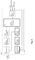
- FIG. 2 shows in a schematic block diagram components of the heart stimulator 10, which are arranged in the interior of the housing 12. The presentation is not necessarily exhaustive. In particular, in Fig. 2 Components shown in dashed lines, in a heart stimulator 10 off Fig. 1 not realized.
- the cardiac stimulator 10 has in its header 14 connection contacts for the connection of corresponding mating contacts of an electrode lead connector at the proximal end of the electrode lead 20. These contacts serve for electrical connection to the electrodes of the electrode lead 20.
- the proximal shock coil 38 is in contact with the contact SVC coil connected, the ventricular (distal) shock coil 26 with the RV coil connection, the right ventricular tip electrode 22 with the RV Tip connector and the right ventricular ring electrode with the RV ring connector.
- the right-ventricular tip electrode 22 and the right-ventricular ring electrode 24 are each connected to a right-ventricular stimulation unit 50 and a right-ventricular sensing unit 52 via the connections RV tip and RV ring.
- the right-ventricular sensing unit 52 is connected on the output side to a stimulation control unit 54, which in turn has an output which is connected to the right-ventricular stimulation unit 50.
- the right ventricular stimulation unit 50 is designed to respond to a corresponding control signal of the stimulation control unit 54 generate a ventricular stimulation pulse and deliver at least over the contact RV Tip.
- the right-ventricular sensing unit 52 is basically designed to evaluate the course of a signal that results from the difference between the potentials present at the terminals RV tip and RV ring.
- This waveform typically includes signal peaks that occur in the case of ventricular depolarizations. Ventricular depolarizations precede contraction of the ventricular myocardium and thus identify ventricular sense events. These can be detected from the signal curve by comparing the potentials with a threshold value. This is set so that the signal peaks associated with ventricular depolarizations exceed the threshold, so that the ventricular sensing unit 52 can detect ventricular sense events by thresholding threshold comparisons.
- Shock generators 56 and 58 are also provided to generate and deliver defibrillation shocks, which are connected to the proximal shock coil 28 via the SVC coil terminal and to the distal shock coil 26 via the RV coil terminal, respectively.
- the two defibrillation shock generators 56 and 58 are each likewise connected to the stimulation control unit 54.
- Further features of the heart stimulator 10 are a timer 60, which is used, for example, for interval measurement and heart rate determination, and an activity sensor 62, which is designed to detect a physical activity of a patient, for example by motion detection, in order to enable the stimulation control unit 54 Stimulation rate to fit the physiological needs of a patient.
- the heart stimulator 10 has a memory 64 for storing control parameters as well as physiological parameters which are obtained, for example, by evaluating the various signals recorded by the heart stimulator 10.
- the heart stimulator 10 also has a telemetry unit 66, via which the heart stimulator 10 can wirelessly transmit acquired and stored physiological parameters to an external device or via which the heart stimulator 10 can receive control parameters that control the operation of the heart stimulator 10.
- the heart stimulator 10 also has a far-field electrocardiogram detection unit 70, which is connected on the input side to a switching matrix 72 via which the far-field electrocardiogram detection unit 70 either with the electrically conductive housing 12 of the heart stimulator 10 and on the other hand via the SVC coil connection with the proximal shock coil 28 or via the connector RV coil with the distal shock coil 26 or via the connector RV ring with the right ventricular ring electrode 24 or via the connector RV tip with the right ventricular tip electrode 22 is to connect.
- the preferred derivatives are variant D, if a proximal shock coil is present, and variant C, if no proximal shock coil is present, since in these derivatives the imaging of the atrial excitation (P-wave) is most favorable.
- the switching matrix 72 is provided in the embodiment, either manually programmable by the user, or automatically selects the most favorable derivative for P-wave determination based on electrode impedances and signal quality.
- a selection unit 78 is provided which evaluates the far-field electrocardiogram signals generated by the far-field electrocardiogram detection unit 70 and actuates the switching matrix 72 accordingly.
- the selection unit 78 is connected on the input side to the far field electrocardiogram detection unit 70 and on the output side to the switching matrix 72.
- a far-field electrocardiogram is obtained, amplified, A / D converted and filtered by far-field electrocardiogram detection unit 70, as described with reference to FIGS FIG. 3 will be explained in more detail.
- the thus obtained and processed far-field electrocardiogram is applied to an output of the far-field electrocardiogram detection unit 70.
- This output is connected to an input of a far-field electrocardiogram evaluation unit 74.
- This far-field electrocardiogram evaluation unit 74 also has an input connected to the right-ventricular sensing unit 52 and to another input connected to the right-ventricular stimulation unit 50.
- a single input of the far-field electrocardiogram evaluation unit 74 which is connected to the stimulation control unit 54, may also be provided.
- the far field electrocardiogram evaluation unit 74 serves to supply the far field electrocardiogram evaluation unit 74 with signals which characterize ventricular sensing events or ventricular stimulation events.
- the far field electrocardiogram evaluation unit 74 is configured to evaluate the far field electrocardiogram formed by the far field electrocardiogram detection unit 70 in consideration of ventricular sensing events and stimulating events of characterizing signals to detect signal features in the far field electrocardiogram that characterize atrial (sense) events. Such signal characteristics are referred to as P-waves.
- the far-field electrocardiogram evaluation unit 74 is connected on the output side to a VT / SVT discrimination unit 76 as part of the stimulation control unit 54.
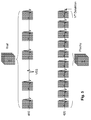
- FIG. 3 those components of a single-chamber ICD are shown which cause a VT / SVT discrimination according to the invention.
- the ICD is connected to a right ventricular electrode lead 20 as a sense and stimulation electrode.
- the intracardiac electrogram derived by means of the electrodes 22 and 24 of this electrode lead 20 is analyzed in a conventional ICD sensing stage 52 and the ventricular intervals (RR interval) are measured. These RR intervals are then classified in an interval classification unit 330 according to their cycle length and assigned to at least one tachycardia zone. If a RR interval falls within a tachycardia zone, a counter is incremented in the tachycardia detection unit 340 accordingly. If a predetermined counter criterion for tachycardia detection in a zone is met, the subsequent VT / SVT discrimination unit 76 is activated.
- the shock electrodes 26 and 28 connected to the shock generator 56/58 of the ICD and the electrically conductive housing 12 are additionally connected to a Far Field ECG selection switching matrix 72/78.
- This select switch matrix 72/78 determines which of the electrodes will be used to derive a far-field electrocardiogram signal for VT / SVT discrimination. The selection is made either manually by programming by the doctor or automatically by a signal quality analysis carried out in the ICD ("Signal Quality Check"). a far-field electrocardiogram signal obtained in this way is subsequently preprocessed (amplified, digitized, filtered) in an electrocardiogram signal processing unit 360 and then supplied to a mean value generator 370.
- This averager performs signal averaging triggered on a ventricular heart action detected by the sensing unit 52 and analyzes the electrocardiogram signal portion before the detected ventricular heart action so as to recognize and classify a P-wave as a signal characteristic characteristic of atrial heart actions.
- the thus-detected P-wave - separated by reference P-wave and P-wave at the time of tachycardia detection (tachycardia P-wave) - is supplied to the VT / SVT disc eliminating unit 76.
- the rhythm corresponding to the in FIG. 6 classified hereby a comparison between the recorded before the tachycardia P-wave and the recorded during tachycardia P-wave (see FIG. 5 ) takes place.
- FIG. 4 shows the results of averaging to detect a P-wave in the Far Field electrogram.
- the first upper curve (210) shows an input signal with an amplitude of 0.1 mV to simulate a very small P-wave.
- the input signal is somewhat noisy to simulate the real conditions of the far-field ECG lead.
- the second, middle curve (220) shows the derivative of these P-waves in the Far Field electrogram, derived with an ICD between the proximal shock coil and the housing of the ICD.
- the noise signals shown next to the P-wave to be detected do not permit automatic P-wave detection by the ICD.
- the third lower curve (230) shows the signal after it has been averaged over 24 cardiac cycles. This signal quality is sufficient to realize an automatic detection of the P-wave in the ICD.
- FIG. 5 the recording of the reference P-wave and the tachycardia P-wave is shown.
- the reference P-waves are recorded as a moving average over a fixed number of intervals (eg 24) so as to always have a current reference template of a P-wave available.
- Extrasystoles (VES) or stimulated events are not included in averaging.
- the averaging is done in a separate averager for intervals within the tachycardia zone so that at the time a tachycardia detection is completed, an averaged P-wave record is available for the VT / SVT classification.
- VT / SVT discrimination algorithm performed a "normal" single-chamber discrimination.
- FIG. 5 is a flowchart illustrating a possible VT / SVT discrimination algorithm based on P-wave averaging before and during a tachycardia.
- test (520) is performed as to whether, in comparison to the reference P-wave (see Figure 4 ) the P-wave, averaged during the Tachycardia either the reference P-wave corresponds to or is inhibited (polarity swapped) or is no longer detectable.
- tachycardia is rated SVT. It is then either sinus tachycardia or atrial tachycardia with a fixed conduction ratio (N: 1) in the ventricle (540).
- tachycardia is rated VT. It is then a monomorphic ventricular tachycardia with a retrograde transition into the atrium (550).
- the tachycardia is rated as VT. It is then a monomorphic ventricular tachycardia without retrograde conduction into the atrium (560).
- the test is made as to whether, in comparison to the reference P-wave (see Figure 4 ) the P-wave, averaged during tachycardia, either corresponds to the reference P-wave or is inhibited (polarity exchanged) or is no longer detectable.
- tachycardia is rated SVT. It is then an atrial tachycardia with a 1: 1 transfer into the ventricle (570).
- tachycardia is rated VT. This is a polymorphic ventricular tachycardia with a retrograde transition into the atrium (580).
- tachycardia is rated SVT. It is then an atrial fibrillation with tachycardiac conduction (590). Alternatively, a classification can also take place in this decision path as VT. In this case, a polymorphic VT would be assumed.
Landscapes
- Health & Medical Sciences (AREA)
- Life Sciences & Earth Sciences (AREA)
- Engineering & Computer Science (AREA)
- Cardiology (AREA)
- Physics & Mathematics (AREA)
- Biophysics (AREA)
- Surgery (AREA)
- Artificial Intelligence (AREA)
- Veterinary Medicine (AREA)
- Public Health (AREA)
- General Health & Medical Sciences (AREA)
- Animal Behavior & Ethology (AREA)
- Molecular Biology (AREA)
- Pathology (AREA)
- Biomedical Technology (AREA)
- Heart & Thoracic Surgery (AREA)
- Medical Informatics (AREA)
- Evolutionary Computation (AREA)
- Mathematical Physics (AREA)
- Fuzzy Systems (AREA)
- Signal Processing (AREA)
- Psychiatry (AREA)
- Physiology (AREA)
- Computer Vision & Pattern Recognition (AREA)
- Electrotherapy Devices (AREA)
Applications Claiming Priority (1)
| Application Number | Priority Date | Filing Date | Title |
|---|---|---|---|
| DE102008043480A DE102008043480A1 (de) | 2008-11-05 | 2008-11-05 | Einkammer-Herzstimulator |
Publications (2)
| Publication Number | Publication Date |
|---|---|
| EP2184009A2 true EP2184009A2 (fr) | 2010-05-12 |
| EP2184009A3 EP2184009A3 (fr) | 2013-12-18 |
Family
ID=41692878
Family Applications (1)
| Application Number | Title | Priority Date | Filing Date |
|---|---|---|---|
| EP09172867.5A Withdrawn EP2184009A3 (fr) | 2008-11-05 | 2009-10-13 | Stimulateur cardiaque à une chambre |
Country Status (3)
| Country | Link |
|---|---|
| US (1) | US8682427B2 (fr) |
| EP (1) | EP2184009A3 (fr) |
| DE (1) | DE102008043480A1 (fr) |
Families Citing this family (3)
| Publication number | Priority date | Publication date | Assignee | Title |
|---|---|---|---|---|
| US8903490B2 (en) * | 2010-03-03 | 2014-12-02 | Cardiac Pacemakers, Inc. | Methods and systems for recognizing arrhythmias using neural stimulation |
| EP2510975A1 (fr) | 2011-04-14 | 2012-10-17 | BIOTRONIK SE & Co. KG | Stimulateur cardiaque |
| US10629308B1 (en) | 2014-11-03 | 2020-04-21 | Shahriar Iravanian | Cardiac electrophysiology simulator |
Family Cites Families (19)
| Publication number | Priority date | Publication date | Assignee | Title |
|---|---|---|---|---|
| US4024574A (en) * | 1975-02-26 | 1977-05-17 | Teleglobe Pay Tv System Inc. | Validation method and apparatus for pay television systems |
| US5354316A (en) * | 1993-01-29 | 1994-10-11 | Medtronic, Inc. | Method and apparatus for detection and treatment of tachycardia and fibrillation |
| US6101417A (en) * | 1998-05-12 | 2000-08-08 | Pacesetter, Inc. | Implantable electrical device incorporating a magnetoresistive magnetic field sensor |
| US6449503B1 (en) * | 1999-07-14 | 2002-09-10 | Cardiac Pacemakers, Inc. | Classification of supraventricular and ventricular cardiac rhythms using cross channel timing algorithm |
| US6567691B1 (en) * | 2000-03-22 | 2003-05-20 | Medtronic, Inc. | Method and apparatus diagnosis and treatment of arrhythias |
| DE10149776B4 (de) | 2001-10-09 | 2006-06-29 | Robert Bosch Gmbh | Sensorvorrichtung zur Messung von Magnetfeldern und Herstellungsverfahren derselben |
| US7330757B2 (en) * | 2001-11-21 | 2008-02-12 | Cameron Health, Inc. | Method for discriminating between ventricular and supraventricular arrhythmias |
| US6941168B2 (en) * | 2001-12-12 | 2005-09-06 | Cardiac Pacemakers, Inc. | System and method for treating an adverse cardiac condition using combined pacing and drug delivery |
| US6937906B2 (en) * | 2002-01-29 | 2005-08-30 | Medtronic, Inc. | Method and apparatus for detecting static magnetic fields |
| US6928324B2 (en) * | 2002-02-14 | 2005-08-09 | Pacesetter, Inc. | Stimulation device for sleep apnea prevention, detection and treatment |
| US7103404B2 (en) * | 2003-02-27 | 2006-09-05 | Medtronic,Inc. | Detection of tachyarrhythmia termination |
| US7242981B2 (en) | 2003-06-30 | 2007-07-10 | Codman Neuro Sciences Sárl | System and method for controlling an implantable medical device subject to magnetic field or radio frequency exposure |
| US7299086B2 (en) * | 2004-03-05 | 2007-11-20 | Cardiac Pacemakers, Inc. | Wireless ECG in implantable devices |
| US7212849B2 (en) * | 2004-10-28 | 2007-05-01 | Cardiac Pacemakers, Inc. | Methods and apparatuses for arrhythmia detection and classification using wireless ECG |
| US8005544B2 (en) * | 2004-12-20 | 2011-08-23 | Cardiac Pacemakers, Inc. | Endocardial pacing devices and methods useful for resynchronization and defibrillation |
| US7474916B2 (en) * | 2005-04-28 | 2009-01-06 | Medtronic, Inc. | Method and apparatus for discriminating ventricular and supraventricular tachyarrhythmias |
| US20060293591A1 (en) | 2005-05-12 | 2006-12-28 | Wahlstrand John D | Implantable medical device with MRI and gradient field induced capture detection methods |
| DE102005049009A1 (de) * | 2005-10-11 | 2007-04-12 | Biotronik Crm Patent Ag | Implantierbare Vorrichtung zur Herzvektor-Bestimmung |
| US20080154342A1 (en) * | 2006-12-21 | 2008-06-26 | Dennis Digby | Implantable medical device comprising magnetic field detector |
-
2008
- 2008-11-05 DE DE102008043480A patent/DE102008043480A1/de not_active Withdrawn
-
2009
- 2009-10-08 US US12/575,499 patent/US8682427B2/en not_active Expired - Fee Related
- 2009-10-13 EP EP09172867.5A patent/EP2184009A3/fr not_active Withdrawn
Also Published As
| Publication number | Publication date |
|---|---|
| DE102008043480A1 (de) | 2010-05-06 |
| US20100114213A1 (en) | 2010-05-06 |
| US8682427B2 (en) | 2014-03-25 |
| EP2184009A3 (fr) | 2013-12-18 |
Similar Documents
| Publication | Publication Date | Title |
|---|---|---|
| DE60222071T2 (de) | Implantierbares Herzschrittmachersystem mit Kalibrierung für automatische Erregungsbestätigung | |
| DE60122820T2 (de) | Vorrichtung zur Verringerung der Effekte von evozierten Potentialen bei Polarisationsmessungen in einem Herzschrittmachersystem mit automatischer Erfassung des Einfanges | |
| DE60020514T2 (de) | Verfahren zur Unterscheidung von im Herzen erfassten elektrischen Ereignissen und entsprechendes System | |
| DE69921441T2 (de) | Vorhof-kardiovertierer sowie anordnung zur anzeige von vorhof-tachyarrythmie mittels fensterdiskriminator | |
| DE60026477T2 (de) | Implantierbarer Herzschrittmacher und Verfahren zur Unterscheidung zwischen atrialen und ventrikulären Arrhythmien | |
| DE69700748T2 (de) | Egm aufzeichnungssystem für implantierbare medizinische vorrichtung | |
| US8386024B2 (en) | Method and apparatus for identifying oversensing using far-field intracardiac electrograms and marker channels | |
| DE60132407T2 (de) | Implantierbarer Herzschrittmacher mit automatischer Auswahl der Elektrodenanordnung zur Detektion der evozierten Reaktion | |
| DE69306785T2 (de) | Vorrichtung zur unterscheidung von ventrikulärer und supraventrikulärer tachykardie, sowie vorrichtung zur unterscheidung von schnellem herzrhythmus aus sinus- und nicht-sinus-ursprung | |
| DE60319223T2 (de) | Vorrichtung zur verhütung von arrhythmie-häufungen unter verwendung von schnellgang-impulsgebung | |
| EP2353644B1 (fr) | Cardioverteur/défibrillateur et dispositif de traitement de signal pour la classification de signaux intra-cardiaux | |
| DE102007054178A1 (de) | Biventrikulärer Herzstimulator | |
| DE60031640T2 (de) | Vorrichtung zur Erkennung einer natürlichen elektrischen Kohärenz im Herz und zur Verabreichung einer darauf basierenden Therapie | |
| EP2676697B1 (fr) | Capteur de dislocation | |
| EP2181648B1 (fr) | Stimulateur cardiaque à une chambre | |
| EP2111892B1 (fr) | Stimulateur cardiaque contre la tachychardie | |
| EP1302158B1 (fr) | Appareil de prédiction de tachyarythmie | |
| EP2184009A2 (fr) | Stimulateur cardiaque à une chambre | |
| EP2111893A1 (fr) | Stimulateur cardiaque ventriculaire | |
| EP2140910B1 (fr) | Stimulateur cardiaque destiné au traitement des rythmes tachycardiques | |
| EP2111894B1 (fr) | Stimulateur cardiaque doté d'un contrôle de la réussite de la stimulation | |
| EP2135641A1 (fr) | Stimulateur cardiaque contre la tachycardie | |
| EP2826524B1 (fr) | Appareil de traitement cardiaque destiné à détecter des tachycardies ou fibrillations ventriculaires | |
| EP2250962B1 (fr) | Détecteur de dispersion à ondes P implantable | |
| DE10361143A1 (de) | Intrakardiale Impedanzmessanordnung |
Legal Events
| Date | Code | Title | Description |
|---|---|---|---|
| PUAI | Public reference made under article 153(3) epc to a published international application that has entered the european phase |
Free format text: ORIGINAL CODE: 0009012 |
|
| AK | Designated contracting states |
Kind code of ref document: A2 Designated state(s): AT BE BG CH CY CZ DE DK EE ES FI FR GB GR HR HU IE IS IT LI LT LU LV MC MK MT NL NO PL PT RO SE SI SK SM TR |
|
| AX | Request for extension of the european patent |
Extension state: AL BA RS |
|
| PUAL | Search report despatched |
Free format text: ORIGINAL CODE: 0009013 |
|
| AK | Designated contracting states |
Kind code of ref document: A3 Designated state(s): AT BE BG CH CY CZ DE DK EE ES FI FR GB GR HR HU IE IS IT LI LT LU LV MC MK MT NL NO PL PT RO SE SI SK SM TR |
|
| AX | Request for extension of the european patent |
Extension state: AL BA RS |
|
| RIC1 | Information provided on ipc code assigned before grant |
Ipc: A61N 1/362 20060101ALI20131113BHEP Ipc: A61B 5/00 20060101ALI20131113BHEP Ipc: A61B 5/0464 20060101AFI20131113BHEP |
|
| STAA | Information on the status of an ep patent application or granted ep patent |
Free format text: STATUS: THE APPLICATION IS DEEMED TO BE WITHDRAWN |
|
| 18D | Application deemed to be withdrawn |
Effective date: 20140619 |