EP2184010A1 - Vorrichtung zur verstärkung der weissen substanz, verfahren zur verstärkung der weissen substanz und programm - Google Patents
Vorrichtung zur verstärkung der weissen substanz, verfahren zur verstärkung der weissen substanz und programm Download PDFInfo
- Publication number
- EP2184010A1 EP2184010A1 EP08777674A EP08777674A EP2184010A1 EP 2184010 A1 EP2184010 A1 EP 2184010A1 EP 08777674 A EP08777674 A EP 08777674A EP 08777674 A EP08777674 A EP 08777674A EP 2184010 A1 EP2184010 A1 EP 2184010A1
- Authority
- EP
- European Patent Office
- Prior art keywords
- white
- brain
- matter
- image
- enhanced
- Prior art date
- Legal status (The legal status is an assumption and is not a legal conclusion. Google has not performed a legal analysis and makes no representation as to the accuracy of the status listed.)
- Granted
Links
Images










Classifications
-
- A—HUMAN NECESSITIES
- A61—MEDICAL OR VETERINARY SCIENCE; HYGIENE
- A61B—DIAGNOSIS; SURGERY; IDENTIFICATION
- A61B5/00—Measuring for diagnostic purposes; Identification of persons
- A61B5/05—Detecting, measuring or recording for diagnosis by means of electric currents or magnetic fields; Measuring using microwaves or radio waves
- A61B5/055—Detecting, measuring or recording for diagnosis by means of electric currents or magnetic fields; Measuring using microwaves or radio waves involving electronic [EMR] or nuclear [NMR] magnetic resonance, e.g. magnetic resonance imaging
-
- A—HUMAN NECESSITIES
- A61—MEDICAL OR VETERINARY SCIENCE; HYGIENE
- A61B—DIAGNOSIS; SURGERY; IDENTIFICATION
- A61B5/00—Measuring for diagnostic purposes; Identification of persons
- A61B5/103—Measuring devices for testing the shape, pattern, colour, size or movement of the body or parts thereof, for diagnostic purposes
- A61B5/107—Measuring physical dimensions, e.g. size of the entire body or parts thereof
-
- G—PHYSICS
- G01—MEASURING; TESTING
- G01R—MEASURING ELECTRIC VARIABLES; MEASURING MAGNETIC VARIABLES
- G01R33/00—Arrangements or instruments for measuring magnetic variables
- G01R33/20—Arrangements or instruments for measuring magnetic variables involving magnetic resonance
- G01R33/44—Arrangements or instruments for measuring magnetic variables involving magnetic resonance using nuclear magnetic resonance [NMR]
- G01R33/48—NMR imaging systems
- G01R33/54—Signal processing systems, e.g. using pulse sequences ; Generation or control of pulse sequences; Operator console
- G01R33/56—Image enhancement or correction, e.g. subtraction or averaging techniques, e.g. improvement of signal-to-noise ratio and resolution
- G01R33/5608—Data processing and visualization specially adapted for MR, e.g. for feature analysis and pattern recognition on the basis of measured MR data, segmentation of measured MR data, edge contour detection on the basis of measured MR data, for enhancing measured MR data in terms of signal-to-noise ratio by means of noise filtering or apodization, for enhancing measured MR data in terms of resolution by means for deblurring, windowing, zero filling, or generation of gray-scaled images, colour-coded images or images displaying vectors instead of pixels
-
- G—PHYSICS
- G06—COMPUTING OR CALCULATING; COUNTING
- G06T—IMAGE DATA PROCESSING OR GENERATION, IN GENERAL
- G06T5/00—Image enhancement or restoration
- G06T5/90—Dynamic range modification of images or parts thereof
-
- A—HUMAN NECESSITIES
- A61—MEDICAL OR VETERINARY SCIENCE; HYGIENE
- A61B—DIAGNOSIS; SURGERY; IDENTIFICATION
- A61B2576/00—Medical imaging apparatus involving image processing or analysis
- A61B2576/02—Medical imaging apparatus involving image processing or analysis specially adapted for a particular organ or body part
- A61B2576/026—Medical imaging apparatus involving image processing or analysis specially adapted for a particular organ or body part for the brain
-
- G—PHYSICS
- G01—MEASURING; TESTING
- G01R—MEASURING ELECTRIC VARIABLES; MEASURING MAGNETIC VARIABLES
- G01R33/00—Arrangements or instruments for measuring magnetic variables
- G01R33/20—Arrangements or instruments for measuring magnetic variables involving magnetic resonance
- G01R33/44—Arrangements or instruments for measuring magnetic variables involving magnetic resonance using nuclear magnetic resonance [NMR]
- G01R33/48—NMR imaging systems
- G01R33/54—Signal processing systems, e.g. using pulse sequences ; Generation or control of pulse sequences; Operator console
- G01R33/56—Image enhancement or correction, e.g. subtraction or averaging techniques, e.g. improvement of signal-to-noise ratio and resolution
- G01R33/5602—Image enhancement or correction, e.g. subtraction or averaging techniques, e.g. improvement of signal-to-noise ratio and resolution by filtering or weighting based on different relaxation times within the sample, e.g. T1 weighting using an inversion pulse
-
- G—PHYSICS
- G06—COMPUTING OR CALCULATING; COUNTING
- G06T—IMAGE DATA PROCESSING OR GENERATION, IN GENERAL
- G06T2207/00—Indexing scheme for image analysis or image enhancement
- G06T2207/10—Image acquisition modality
- G06T2207/10072—Tomographic images
- G06T2207/10088—Magnetic resonance imaging [MRI]
-
- G—PHYSICS
- G06—COMPUTING OR CALCULATING; COUNTING
- G06T—IMAGE DATA PROCESSING OR GENERATION, IN GENERAL
- G06T2207/00—Indexing scheme for image analysis or image enhancement
- G06T2207/30—Subject of image; Context of image processing
- G06T2207/30004—Biomedical image processing
- G06T2207/30016—Brain
-
- G—PHYSICS
- G16—INFORMATION AND COMMUNICATION TECHNOLOGY [ICT] SPECIALLY ADAPTED FOR SPECIFIC APPLICATION FIELDS
- G16H—HEALTHCARE INFORMATICS, i.e. INFORMATION AND COMMUNICATION TECHNOLOGY [ICT] SPECIALLY ADAPTED FOR THE HANDLING OR PROCESSING OF MEDICAL OR HEALTHCARE DATA
- G16H30/00—ICT specially adapted for the handling or processing of medical images
- G16H30/40—ICT specially adapted for the handling or processing of medical images for processing medical images, e.g. editing
Definitions
- the present invention relates to an apparatus for white-matter-enhancement processing, and a method and a program for white-matter-enhancement processing; it particularly concerns an apparatus for white-matter-enhancement processing and a method and program for white-matter-enhancement processing that utilize contrast images of the brain of a living body obtained by means of a magnetic resonance imaging (MRI) apparatus.
- MRI magnetic resonance imaging
- CT computed tomography scanning
- MRI apparatus and the like are generally known as apparatus for imaging the shape of the brain.
- a CT apparatus is an apparatus that uses the method of computed tomographic imaging: a device for outputting x-ray radiation rotates around a living body and irradiates it from multiple directions, and a computer performs calculations on the detected data to create images.
- An MRI apparatus is an apparatus that uses the method of magnetic resonance imaging: the spin of atomic nuclei of the body tissue of a subject placed in a static magnetic field is excited by high wavelength signals for the particular Larmor frequency for those nuclei, and images are created from magnetic resonance signals that are given off accompanying this excitation.
- Each of these apparatus -- CT and MRI -- has been developed with the goal of detecting brain structure, brain lesions, and the like.
- the CT apparatus can clearly distinguish between the skull and the brain matter, it is used for preoperative examination before brain surgery. It is also capable of rendering blood vessels as small as 1 mm.
- CT is not performed on healthy persons as a rule, and it is only selected as a last option and used when there is a suspicion of illness.
- a CT scan of the lungs might be performed in a regularly scheduled physical examination, but this would be to find a small tumor in the lungs, or the like.
- the use of CT apparatus is restricted in brain structural imaging because of radiation exposure.
- images can be obtained distinguishing the cortex and the white matter of the brain, they have not been as clear as could be desired.
- the MRI apparatus With the MRI apparatus, on the other hand, there are no constraints on its use in brain structural imaging because there is no fear of radiation exposure, and images can be obtained as easily and freely as photographs of the brain. Currently, because it can even detect brain lesions of around 1 mm, it is used even in regularly scheduled physical examinations. Three-dimensional (3D) MRI is also commonly used, and it has become possible to investigate the structure of the brain in detail by reconstructing it from any angle. In addition, the MRI apparatus does an excellent job of visualizing the brain structure at the corticomedullary junction, which divides the cortex and the white matter.
- T1-weighted imaging Five types of imaging methods are normally used in brain MRI: T1-weighted imaging, proton-weighted imaging, T2-weighted imaging, FLAIR imaging and diffusion-weighted imaging.
- T1-weighted images the white matter is rendered in white, and the cortex, in gray. Lesions are mainly rendered in shades of black.
- T2-weighted images and FLAIR images the white matter is, conversely, rendered in black, and the cortex, in gray. Lesions are mainly rendered in white.
- Patent Reference 1 proposes a magnetic resonance imaging method and apparatus in which, in a magnetic resonance imaging method wherein a subject body placed in a static magnetic field is subjected first to an inversion sequence including inversion pulses, and after the inversion sequence, to an imaging sequence for collecting magnetic resonance signals from the subject body, the frequency band width of the inversion pulses is set wider than previously used bandwidths.
- This magnetic resonance imaging method and apparatus makes it possible, in magnetic resonance imaging using an IR series sequence including inversion pulses, to perform imaging that actively utilizes the phenomena of chemical exchange and/or cross relaxation among a pool of a plurality of kinds of atomic nuclei; and it is stated, for example, that contrast is improved between white matter and gray matter and the like, and that the S/N ratio is improved, thus improving, for example, its ability to render brain neural tissue, and making it possible to obtain MRI images of previously unobtainable high quality.
- Previous Example 1 This technology will be referred to below as Previous Example 1.
- Patent Reference 2 proposes a magnetic resonance imaging apparatus in which, in a magnetic resonance imaging apparatus provided with an acquisition means, whereby a nuclear magnetic resonance signal is generated at the subject body under specified conditions of image acquisition and then detected, a reconstruction means for reconstructing tomographic images of the subject body based on nuclear magnetic resonance signals, a display means for displaying tomographic images of the subject body, and a control means for controlling the image acquisition means, the reconstruction means and the display means; the control means continuously displays at least 2 types of contrast images on the same screen or on a plurality of screens.
- 2 types of contrast images such as a proton density-weighted image and a T2-weighted image, a T1-weighted image and a T2-weighted image, or a fat-water synthetic image and a fat-suppressed image can be selected according to the lesion being targeted.
- This magnetic resonance imaging apparatus is said to make it possible to advance a puncture needle, biopsy needle or the like to a lesion site in a subject body with an image corresponding to the lesion and rendered with higher contrast as a guide. (This technology will be referred to below as Previous Example 2.)
- Previous Example 1 and Previous Example 2 were technologies for the purpose of improving the rendering of contrast images in order to specify the range, size, location and the like of a lesion; they were not technologies for the purpose of analyzing distinguishing characteristics of the brain of a living body, such as degree of growth and development, left/right brain dominance, identification of areas of strength and weakness, and personality traits of the brain of the living body.
- the apparatus for white-matter-enhancement processing of the present invention comprises means for creating a white-matter-enhanced image for enhancing white matter, based on a contrast image of the brain of a living body obtained by means of an MRI apparatus, in which the white matter is enhanced by adjusting the contrast image in such a way that the white matter stands out and the cortex does not stand out, and means for displaying the white-matter-enhanced image that was created.
- the contrast image is, for example, a T1-weighted image, a proton density-weighted image, a T2-weighted image, a FLAIR image or a diffusion-weighted image, or an image that is a combination thereof.
- the white-matter-enhanced image may be created by adjusting the window width and window level.
- the invention may have a means for analyzing distinguishing characteristics of a brain of a living body, based on the number, thickness, length, location, intensity, shape or size, or a combination of these characteristics, of the branches in the white-matter-enhanced image that was created.
- the analysis means may create and analyze a plurality of types of classifications based on characteristics of the white-matter-enhanced images of brains of living bodies.
- the method for white-matter-enhancement processing of the present invention comprises the steps of:
- the program of the present invention makes the computer execute the processes of:
- the present invention by creating white-matter-enhanced images in which the brain white matter is enhanced from contrast images of the brain of a living body obtained from an MRI apparatus, makes it possible to analyze distinguishing characteristics of the brain of a living body, such as degree of growth and development of the brain of the living body, left/right brain dominance, identification of areas of strength and weakness, and personality traits of the living body.
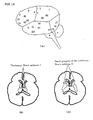
- FIG. 1 is a block diagram showing the constitution of a white-matter-enhancement processing apparatus of an example of an embodiment of the present invention.
- white-matter-enhancement processing apparatus A of an example of an embodiment of the present invention has an input part 1 constituting a keyboard, a mouse and the like for inputting various data, an output part (display part) 2 constituting a display and the like, and a control part 3, which controls input part 1 and display part 2; and it is connected to MRI apparatus B through an interface part 4.
- Control part 3 has a memory part 5 for inputting and storing contrast images of the brain of a living body, obtained by means of MRI apparatus B; a white-matter-enhanced image-creating part 6 for creating white-matter-enhanced images based on contrast images stored in recording part 5, in which the white matter is enhanced by adjusting the images in such a way that the white matter stands out and the cortex does not stand out; a display processing part 7 for displaying on output part 2 the white-matter-enhanced images created by means of white-matter-enhanced image-creating part 6; and a branching analysis part 8 for analyzing distinguishing characteristics of the brain of the living body, based on any one of or a combination of the characteristics of branches in the white-matter-enhanced images that are created: their number, thickness, length, location, intensity, shape and/or size.
- Contrast images input from MRI apparatus B can be any of T1-weighted images, proton-weighted images, T2-weighted images or diffusion-weighted images, or a combination thereof.
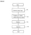
- Figure 2 is a flow chart for explaining the operation of a white-matter-enhancement processing apparatus of an example of an embodiment of the present invention.
- a contrast image of the brain of a living body obtained by means of MRI apparatus B is input (Step S1).
- the imaging parameters repetition time (TR) and echo time (TE) are adjusted to enhance the contrast between the cortex and the white matter.
- TR repetition time
- TE echo time
- TR is set at around 4000 ms
- TE at 20-200 ms.
- a horizontal cross-section, or a coronal cross-section is preferable to a sagittal cross-section.
- a white-matter-enhanced image is created based on the input contrast image, in which the white matter is enhanced by adjusting the image in such a way that the white matter stands out and the cortex does not stand out (Step S2).
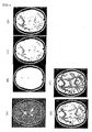
- FIG 3 are explanatory views for explaining the process of creating a white-matter-enhanced image.
- a white-matter-enhanced image is created by the operation of input part 1 by an operator to adjust the window width and window level.
- the contrast image is a T2-weighted image ( Figure 3(A) )
- the window width is set to zero or around zero to make the cortex white ( Figure 3(B) ) and the window level is gradually increased from zero to 200-300 to make all the white matter black ( Figure 3, (B)-(E) ), and a white-matter-enhanced image ( Figure 3(F) ) is thus obtained.
- the white-matter-enhanced image created is subsequently displayed by means of output part 2 (Step S3).
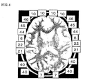
- addresses for demarcating regions of the brain which are assigned demarcating sites where specified functions and roles are performed in the brain of a living body (called "brain addresses” in Japanese, nou banchi: registered trademark by the inventor), may also be displayed together with the white-matter-enhanced image.
- Figure 4 is an explanatory view showing an example in which addresses for demarcating regions of the brain are displayed together with a white-matter-enhanced image.
- addresses for demarcating regions of the brain are explained.
- the present inventor has already applied for a patent for the invention of these addresses for demarcating regions of the brain (Japan Patent Application No. 2006-194357 .
- Figure 5 is an explanatory view in which brain addresses are applied to a 2-dimensional drawing of the brain seen from the outside;
- Figure 6 is an explanatory view in which brain addresses are applied to a 2-dimensional drawing of the brain seen from the inside;
- Figure 7 is an explanatory view in which brain addresses are applied to a 2-dimensional drawing of the brain seen from straight above;
- Figure 8 is an explanatory view in which brain addresses are applied to a 2-dimensional drawing of the brain seen from the front;
- Figure 9 is an explanatory view in which brain addresses are applied to a 3-dimensional drawing of the brain seen from the left back;
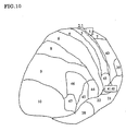
- Figure 10 is an explanatory view in which brain addresses are applied to a 3-dimensional drawing of the brain seen from the left front;
- Figure 11 (A) is an explanatory view in which brain addresses are applied to an external side view, and (B) is an explanatory view in which brain addresses are applied to a horizontal cross-sectional view.
- addresses for demarcating regions of the brain are numbers applied to demarcate sites that perform given functions and roles in the brain.
- numbers (1-47) are assigned following the distribution map of brain cell structure according to Brodmann (1907).
- Brain addresses 4 and 3 form the boundary between the frontal lobe and the parietal lobe; numbers 1 and 2 are in a higher position in the head (see Figure 7 ), and numbers are assigned to the front and back around these numbers.
- Numbers 13-16 form the insular cortex (see Figure 11 ).
- FIG 12 (A) is a brain cell distribution map of a monkey brain, seen from the outside; (B) is a brain cell distribution map of a monkey brain, seen from the inside; (C) is a brain cell distribution diagram of a human brain, seen from the outside; and (D) is a brain cell distribution map of a human brain, seen from the inside;
- Figure 13 is an explanatory view showing the "super-brain areas"; and
- Figure 14 is an explanatory view showing the relationship between the super-brain areas and the brain addresses.
- these 3 regions were found to correspond to the regions that are the latest to develop. Accordingly, as shown in Figures 13 and 14 , the present inventor has named these regions the "super-brain areas”, and named each of these 3 regions, in the frontal lobe, the parietal lobe and the temporal lobes, the "super-frontal area”, the “super-parietal area”, and the "super-temporal areas”, respectively.
- “super-frontal area” applies to the brain addresses 9, 10 and 11; “super-parietal area” applies to brain addresses 39 and 40; and “super-temporal area” applies to 34, 35, 36, 37, 38 and part of 20.
- Figure 15(A) is an example of a brain address map showing the hippocampus (H brain address), the amygdaloid complex (A brain address), the cerebellum (C brain address) and the brain stem (S brain address).
- Figure 15(B) shows the thalamus (T brain address), and
- Figure 15(C) shows the basal ganglia of the cerebrum (G brain address).
- the brain is divided up into areas, taking into consideration simultaneously the sites (regions) of the brain and their functions/roles, and while referencing the classification according to Brodmann, and the brain addresses are the numbers and letters given to each of these areas.
- these brain addresses because they are demarcated based on the shape of the brain and take into consideration not only the different types of cells, but also brain development and growth, and differences between monkeys and humans, it becomes possible to roughly identify localized functional regions of the cerebrum, even if examination of the shape of the brain by MRI and the like cannot differentiate between different types of brain cells.
- the brain address list (invention of Japan patent application no. 2006-194357 , applied for by the present inventor) is matched to the brain addresses of the subject; and because well-developed branches and underdeveloped branches can be distinguished from the branching of the brain, the functions of those branches can be judged to be strengths and weaknesses of the subject. In addition, this is not necessarily limited to single brain addresses, and networking between relevant brain addresses can thus be judged to be well developed if the blackest branches are interconnected.
- Step S4 the distinguishing characteristics of the brain of the living body are analyzed (Step S4), based on the branching of the white-matter-enhanced images created (for example, the number, thickness, length, location, intensity, shape or size of the branches, or a combination thereof).
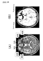
- Figure 16 (A) shows a T2-weighted image
- (B) shows the corresponding white-matter-enhanced image.
- FIG 16 (B) because the corpus callosum and left and right brain address nos. 10 are taken as a benchmark, left/right frontal lobe dominance can be decided both qualitatively and quantitatively. Namely, because the branches in no. 10 of the right brain are thick and dark, while the branches in no. 10 of the left brain have already turned white at this window level, the right brain can be seen to be dominant.
- brain addresses 46 and 45 are dominant on the right and thinner and lighter-colored on the left, we can judge that the subject is better at non-verbal work than at language-related work.
- Figure 17 (A) and (B) are explanatory views for explaining a quantitative measurement method for use in white-matter-enhanced images.
- Branch length L as shown in figure 17 (A) , is measured for each of nos. 10, 46 and 45, left and right.
- Branch width (thickness) H as shown in figure 17 (B) , is also measured for each of nos. 10, 46 and 45, left and right.
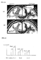
- Figure 18 (A) and (B) are explanatory views for explaining a method for quantitative measurement in white-matter-enhanced images.
- the number of black pixels is counted for each or all addresses, divided by the centerline, as shown in figure 18 (A) , to calculate the surface area or, taking the image thickness into consideration, the volume of the left and right white matter.
- the black/white density is calculated for the surface area or, taking the image thickness into consideration, the volume of white matter, for an arbitrary left/right facing region, divided by the centerline, as shown in figure 18 (B) .
- Figure 19 is a graph showing the number of voxels (volumetric pixels) in the white matter portion of the right and left brain for brain mapping addresses in a white-matter-enhanced image.
- a Laterality Index LI
- R / L / R + L LI LI moves between -1 and +1. If LI is negative, left brain dominance is strong, and if it is positive, right brain dominance is strong.
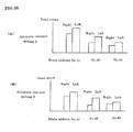
- Figure 20 is a graph showing the number of voxels in the white matter portion of the left and right brain in a white-matter-enhanced image for brain mapping addresses; in (A), the contrast is set at arbitrary contrast A, and in (B), at arbitrary contrast B.
- the contrast ratio ( W / C ) E
- W the contrast ratio between the cortex ( C ) and the white matter ( W )
- WW window width
- WL window level
- Figure 21 is an explanatory view showing an example in which brain branching from two contrast MRI images obtained at different times is compared quantitatively. As shown in figure 21 , the thickness and shape, etc. of the corpus callosum 9 have changed with growth, but by making the corpus callosum 9, located medially between the left and right brain, the same color, it becomes possible to compare other brain addresses.
- Figure 22 is an explanatory view for explaining an example of an image showing left/right brain address dominance. As shown in figure 22 , it can also be made possible to immediately recognize left/right brain address dominance, as in left dominance for address no. 45 and right dominance for address no. 21, by taking either the left or the right of an arbitrary brain address as a benchmark.
- Figure 23 is an explanatory view for explaining an example of an image displaying brain branching contours.
- by a similar method by comparing 2 MRIs from the same person at different times, the growth in area and volume of brain address branches can be measured, thus differentiating between branches showing marked growth and branches without growth.
- Figures 24 (A) through (D) are explanatory views for explaining an example of classification of brain branching into stages in the process of development and growth of the brain gyrus, and (E) is an explanatory view for explaining an example of mapping those stages.
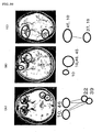
- 10 corresponds to white matter fibers, and 11, the cortex. Tips of brain branches are classified as stages 1-4, as shown in figures 24 (A) through (D) , and by mapping the stages of growth that correspond to that template, as shown in figure 24 (E) , it is possible to convert the state of growth of the branching the entire brain into numerical values.
- the stage of each branch is determined, and then the pixel count (image area) or the voxel count (volume), are calculated from the MRI brain image, and the pixel count (or voxel count) is multiplied by the stage number to give a numerical value.
- the brain branching growth age can be calculated. For example, if the stages of the gyrus development/growth process are set at 10-year intervals, as shown below, stages are mapped for each brain address and those average values are defined as brain branching growth ages:
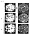
- Figure 25 (A) is a T2-weighted image showing a sagittal cross-section of a brain; (B) and (C) are images that make visible the differences between branching in the corpus callosum.
- the connections between the branching of the different lobes can be seen in figure 25 (C) : the genu 12 of the corpus callosum connects between the brain addresses of the frontal regions in the front of the head, the splenium 13 connects between the brain addresses of the occipital lobe, and the body of the corpus callosum connects brain addresses of the frontal lobe and the parietal lobe.
- Figure 26 (A) and (B) are explanatory views showing white-matter-enhanced images that show the growth of brain branching.
- the cerebral basal ganglia and the thalamus are taken as a benchmark, it becomes easy to differentiate brain branching growth, even between different individuals, as shown in figures 26 (A) and (B) .
- Figure 27 is explanatory views showing (A), a T1-weighted image with a lesion, and (B), an enhanced image in which the lesion is white, the cortex is black and the white matter branching is white.
- FIG 27 (B) by making the lesion white as a benchmark, distortion of the branches becomes visible at a glance. In addition, the lesion can be seen to be pressing on the white matter branches.
- Figure 28 is explanatory views showing (A), a FLAIR-weighted image with a lesion, and (B), a branching-enhanced image in which the lesion is white, the cortex is white and the white matter is made black.
- FIG 28 (B) by making the lesion white as a benchmark, distortion of the branches becomes visible at a glance. In addition, the lesion can be seen to be pressing on the white matter branches.
- Figure 29 is an explanatory view for explaining the determination of proximal lobe dominance utilizing white-matter-enhanced (branching-enhanced) images of the brain; the images in the bottom row are T2-weighted images; and those in the upper row, white-matter-enhanced images: in (A), the left and right hemispheres are symmetrical; in (B), the right brain is dominant; and in (C), the left brain is dominant.
- the present inventor does not examine left/right brain differences utilizing the sulci of the cortical matter, but has investigated healthy subjects, using branching of the white matter of the brain as an index. In doing so, this inventor found that there was individual variation in the branching of the left and right super-frontal regions. Furthermore, after looking at the brains of as many as 50 healthy subjects, this inventor discovered the existence of three types, as shown in figure 29 : right brain dominant super-frontal region branching, left/right symmetrical branching, and left brain dominant super-frontal region branching. This shows that even without injury to a part of the brain addresses, there is individuality in the growth of the brain branches in the growth process.
- Figure 30 (A) through (C) are explanatory views showing brain address mapping utilizing brain branching images.
- Figure 30 (A) shows a left/right frontal lobe right brain dominant network
- (B) shows a right frontal lobe dominant network
- (C) shows a left brain dominant network.
- Figure 33 is explanatory views: (A) shows a T2-weighted image, and (B), a brain branching image. As shown by the arrows in figure 33 , the image of small moth-holes in the branches, namely, lacunar infarcts in the cerebral white matter 18 are found to be clearly displayed.
- the embodiment of the present invention displays excellent effects, such as the following:
- the strongest brain addresses and lowest brain addresses can be distinguished and extracted from branching that is color-coded. The difference between developed brain addresses and weakened brain addresses can be seen visually.
- Branching characteristics such as the strongest addresses and left/right differences, can be quickly extracted from contour images. They can be displayed as maps to brain addresses, contour maps with brain addresses, and so on.
- brain branching growth begins to occur actively. This is around 2 months before a child is born and enters the world outside.
- brain branching growth occurs, the branches run unrestrainedly within the confines of the brain.
- this growth process is observed with MRI and followed closely over the years, different things become apparent from when this narrow world was observed with a microscope.
- One difference is vectors of branching growth that advance in 3 directions inside the brain.
- the brain addresses related to touch, hearing and sight are located divided in 3 directions, much like Fleming's rule.
- Figure 34 is an explanatory view showing brain branching growth vectors. As shown in figure 34 , if you feel the occipital area from outside the scalp, there is a protruding part known as the occipital protuberance in the occipital lobe. Inside this protruding part are the sight-related brain addresses, the location of "seeing”. Sight-related addresses are located perpendicular to the hearing-related brain addresses, which are right near the right and left ears, in a horizontal plane.
- the sensory-related brain address 3, which is involved in the sense of touch, such as skin touch, and motor-related brain address 4, which moves the body, are located parallel to each other, as if drawn in arcs from the left and right ears.
- the motor-related brain address is not included in the senses, it is contiguous with the sensory-related brain address and grows together with it. This locational relationship suggests that not only the senses, but also the ability to move the body are essential to building the foundation of brain growth. In this way, branches growing from the deep regions of the brain, such as the thalamus, are built up solidly from around birth through infancy towards the motor/sensory-related addresses, vision-related addresses and hearing-related addresses.
- the sight-related addresses spread their branches from the optic radiation
- the hearing-related addresses spread their branches from the auditory radiation
- the motor/sensory-related addresses spread their branches from the pyramidal tract.
- t-related addresses develop intricately as the frontal lobe white matter spreads its branches.
- branching can be displayed in such a way that it is possible to determine which of the brain addresses -- vision-related, hearing-related, motor/sensory-related or thought-related - is growing dominantly, also including left/right dominance for those branches. That is, it is possible to extract the characteristics of each of these systems even within the entire brain, and view the individuality of the brain from its branching.
- the present invention creates white-matter-enhanced images in which the brain white matter is enhanced from contrast images of the brain of a living body obtained from an MRI apparatus, it can be used for analyzing distinguishing characteristics of the brain of a living body, such as degree of growth and development, left/right brain dominance, identification of areas of strength and weakness, group analysis of white matter growth types, and personality traits of the brain of the living body.
Landscapes
- Health & Medical Sciences (AREA)
- Physics & Mathematics (AREA)
- Life Sciences & Earth Sciences (AREA)
- Engineering & Computer Science (AREA)
- General Health & Medical Sciences (AREA)
- Nuclear Medicine, Radiotherapy & Molecular Imaging (AREA)
- Heart & Thoracic Surgery (AREA)
- Animal Behavior & Ethology (AREA)
- Radiology & Medical Imaging (AREA)
- High Energy & Nuclear Physics (AREA)
- Veterinary Medicine (AREA)
- Public Health (AREA)
- Surgery (AREA)
- Molecular Biology (AREA)
- Medical Informatics (AREA)
- Biophysics (AREA)
- Pathology (AREA)
- Biomedical Technology (AREA)
- General Physics & Mathematics (AREA)
- Artificial Intelligence (AREA)
- Computer Vision & Pattern Recognition (AREA)
- Oral & Maxillofacial Surgery (AREA)
- Dentistry (AREA)
- Signal Processing (AREA)
- Condensed Matter Physics & Semiconductors (AREA)
- Theoretical Computer Science (AREA)
- Magnetic Resonance Imaging Apparatus (AREA)
Applications Claiming Priority (2)
| Application Number | Priority Date | Filing Date | Title |
|---|---|---|---|
| JP2007173550 | 2007-06-29 | ||
| PCT/JP2008/061762 WO2009005013A1 (ja) | 2007-06-29 | 2008-06-27 | 白質強調処理装置、白質強調処理方法及びプログラム |
Publications (3)
| Publication Number | Publication Date |
|---|---|
| EP2184010A1 true EP2184010A1 (de) | 2010-05-12 |
| EP2184010A4 EP2184010A4 (de) | 2013-10-02 |
| EP2184010B1 EP2184010B1 (de) | 2019-05-08 |
Family
ID=40226059
Family Applications (1)
| Application Number | Title | Priority Date | Filing Date |
|---|---|---|---|
| EP08777674.6A Not-in-force EP2184010B1 (de) | 2007-06-29 | 2008-06-27 | Verfahren zur hervorhebung der weissen substanz |
Country Status (5)
| Country | Link |
|---|---|
| US (1) | US9247894B2 (de) |
| EP (1) | EP2184010B1 (de) |
| JP (2) | JP5266220B2 (de) |
| CN (1) | CN101742963B (de) |
| WO (1) | WO2009005013A1 (de) |
Cited By (1)
| Publication number | Priority date | Publication date | Assignee | Title |
|---|---|---|---|---|
| CN112906701A (zh) * | 2021-02-08 | 2021-06-04 | 重庆兆光科技股份有限公司 | 一种基于多注意力神经网络的细粒度图像识别方法及系统 |
Families Citing this family (20)
| Publication number | Priority date | Publication date | Assignee | Title |
|---|---|---|---|---|
| CN101742963B (zh) * | 2007-06-29 | 2012-04-25 | 加藤俊德 | 白质强调处理装置以及白质强调处理方法 |
| DE102009027448A1 (de) * | 2009-07-03 | 2011-01-05 | Forschungszentrum Jülich GmbH | Wissensbasierte Segmentierung schwächungsrelevanter Regionen des Kopfes |
| WO2012032940A1 (ja) * | 2010-09-07 | 2012-03-15 | 株式会社 日立メディコ | 認知症診断支援装置及び認知症診断支援方法 |
| US20120271147A1 (en) * | 2011-04-22 | 2012-10-25 | New York University | Apparatus, method, and computer-accessible medium for b1-insensitive high resolution 2d t1 mapping in magnetic resonance imaging |
| JP2014522283A (ja) * | 2011-06-09 | 2014-09-04 | ウェイク・フォレスト・ユニヴァーシティ・ヘルス・サイエンシズ | エージェントベース脳モデル及び関連方法 |
| JP5804663B2 (ja) * | 2012-12-07 | 2015-11-04 | 国立研究開発法人国立精神・神経医療研究センター | 性向判別装置、タスク実行支援装置、性向判別コンピュータプログラムおよびタスク実行支援コンピュータプログラム |
| JP6510170B2 (ja) * | 2012-12-26 | 2019-05-08 | キヤノンメディカルシステムズ株式会社 | 医用画像診断装置 |
| TW201438666A (zh) * | 2013-04-12 | 2014-10-16 | ming-xun Zhong | 腦區域活化程度的分析及評估方法 |
| JP5641629B1 (ja) * | 2013-10-31 | 2014-12-17 | 株式会社アラヤ・ブレイン・イメージング | 個人特性予測システム、個人特性予測方法及びプログラム |
| WO2015075604A1 (en) * | 2013-11-22 | 2015-05-28 | Koninklijke Philips N.V. | System for measuring cortical thickness from mr scan information |
| TWI525635B (zh) * | 2013-12-17 | 2016-03-11 | 慧榮科技股份有限公司 | 資料儲存裝置及其資料維護方法 |
| CN107110944B (zh) * | 2014-10-17 | 2019-11-22 | 圣纳普医疗(巴巴多斯)公司 | 连接性制图之系统及方法 |
| KR101676789B1 (ko) | 2014-10-21 | 2016-11-16 | 삼성전자주식회사 | 자기 공명 영상 장치 및 자기 공명 영상을 처리하는 방법 |
| JP2017023457A (ja) * | 2015-07-23 | 2017-02-02 | 東芝メディカルシステムズ株式会社 | 医用画像処理装置 |
| CN110177499A (zh) * | 2016-11-21 | 2019-08-27 | 西门子医疗有限公司 | 通过磁共振设备记录头部的诊断测量数据的方法 |
| CN109843157A (zh) * | 2017-05-22 | 2019-06-04 | 艾德脑科技股份有限公司 | 脑波检测装置与方法 |
| JP6705528B2 (ja) * | 2019-04-08 | 2020-06-03 | 大日本印刷株式会社 | 医用画像表示処理方法、医用画像表示処理装置およびプログラム |
| CN110123324B (zh) * | 2019-05-28 | 2020-05-12 | 浙江大学 | 一种婴儿大脑t1加权磁共振成像优化方法 |
| CN112890832A (zh) * | 2021-01-15 | 2021-06-04 | 褚明礼 | 一种基于脑电信息的脑区发育评估及功能评估分析方法 |
| WO2023278288A1 (en) * | 2021-06-27 | 2023-01-05 | Inteneural Networks Inc. | A system and a method for determining cognitive capabilities based on brain image |
Family Cites Families (23)
| Publication number | Priority date | Publication date | Assignee | Title |
|---|---|---|---|---|
| JP3725234B2 (ja) | 1996-03-19 | 2005-12-07 | 株式会社東芝 | 磁気共鳴イメージング装置 |
| JP4343345B2 (ja) | 1999-09-09 | 2009-10-14 | 株式会社日立メディコ | 磁気共鳴イメージング装置 |
| US6584216B1 (en) * | 1999-11-23 | 2003-06-24 | The Trustees Of The University Of Pennsylvania | Method for standardizing the MR image intensity scale |
| US6751495B2 (en) * | 2000-03-31 | 2004-06-15 | Brigham & Womens' Hospital | Method of fast and reliable tissue differentiation using diffusion-weighted magnetic resonance imaging |
| DE60041893D1 (de) * | 2000-11-24 | 2009-05-07 | Kent Ridge Digital Labs | Verfahren und vorrichtungen zur verarbeitung medizinischer bilder |
| DE10100830B4 (de) * | 2001-01-10 | 2006-02-16 | Jong-Won Park | Verfahren zum Segmentieren der Bereiche der weißen Substanz, der grauen Substanz und der Zerebrospinalflüssigkeit in den Bildern des menschlichen Gehirns, und zum Berechnen der dazugehörigen Volumina |
| JP2002209867A (ja) * | 2001-01-10 | 2002-07-30 | Sogen Boku | 脳の磁気共鳴映像から白質と灰白質および脳脊髄液を分離し体積を算出する方法 |
| US20050283053A1 (en) * | 2002-01-30 | 2005-12-22 | Decharms Richard C | Methods for physiological monitoring, training, exercise and regulation |
| US6956373B1 (en) * | 2002-01-02 | 2005-10-18 | Hugh Keith Brown | Opposed orthogonal fusion system and method for generating color segmented MRI voxel matrices |
| US7218763B2 (en) * | 2003-02-27 | 2007-05-15 | Eastman Kodak Company | Method for automated window-level settings for magnetic resonance images |
| JP4885457B2 (ja) | 2005-01-13 | 2012-02-29 | バンドー化学株式会社 | 摩擦伝動ベルト |
| SG125132A1 (en) * | 2005-02-07 | 2006-09-29 | Agency Science Tech & Res | Medical image processing |
| WO2007023522A1 (ja) * | 2005-08-22 | 2007-03-01 | National Center Of Neurology And Psychiatry | 脳疾患の診断支援方法及び装置 |
| JP2007068852A (ja) * | 2005-09-08 | 2007-03-22 | Hitachi Medical Corp | 医用画像表示方法及び医用画像診断装置 |
| US9101282B2 (en) * | 2005-09-22 | 2015-08-11 | Brainlab Ag | Brain tissue classification |
| EP1768041B1 (de) * | 2005-09-22 | 2016-04-13 | Brainlab AG | Klassifikation von Gehirngewebe |
| CN1947655A (zh) * | 2005-10-13 | 2007-04-18 | 中国科学院自动化研究所 | 三维脑磁共振数据处理中的皮层复杂性定量分析方法 |
| JP4838845B2 (ja) | 2006-07-14 | 2011-12-14 | 俊徳 加藤 | 脳区分用番地を用いた教材、育脳装置及びプログラム |
| KR100900258B1 (ko) * | 2006-08-09 | 2009-05-29 | 재단법인서울대학교산학협력재단 | 사람 지능측정을 위한 신경생물학적 방법 |
| US8600135B2 (en) * | 2007-06-28 | 2013-12-03 | Mayo Foundation For Medical Education And Research | System and method for automatically generating sample points from a series of medical images and identifying a significant region |
| CN101742963B (zh) * | 2007-06-29 | 2012-04-25 | 加藤俊德 | 白质强调处理装置以及白质强调处理方法 |
| JP2009050615A (ja) * | 2007-08-29 | 2009-03-12 | Ge Medical Systems Global Technology Co Llc | 磁気共鳴イメージング装置および磁気共鳴画像表示方法 |
| WO2010048438A1 (en) * | 2008-10-22 | 2010-04-29 | The Trustees Of Columbia University In The City Of New York | Images of language-sensitive neurocircuitry as a diagnostic for autism |
-
2008
- 2008-06-27 CN CN2008800227022A patent/CN101742963B/zh not_active Expired - Fee Related
- 2008-06-27 EP EP08777674.6A patent/EP2184010B1/de not_active Not-in-force
- 2008-06-27 WO PCT/JP2008/061762 patent/WO2009005013A1/ja not_active Ceased
- 2008-06-27 JP JP2009521617A patent/JP5266220B2/ja active Active
-
2009
- 2009-12-24 US US12/647,208 patent/US9247894B2/en active Active
-
2013
- 2013-03-22 JP JP2013060941A patent/JP5458453B2/ja active Active
Cited By (2)
| Publication number | Priority date | Publication date | Assignee | Title |
|---|---|---|---|---|
| CN112906701A (zh) * | 2021-02-08 | 2021-06-04 | 重庆兆光科技股份有限公司 | 一种基于多注意力神经网络的细粒度图像识别方法及系统 |
| CN112906701B (zh) * | 2021-02-08 | 2023-07-14 | 重庆兆光科技股份有限公司 | 一种基于多注意力神经网络的细粒度图像识别方法及系统 |
Also Published As
| Publication number | Publication date |
|---|---|
| US20110004092A1 (en) | 2011-01-06 |
| JP5266220B2 (ja) | 2013-08-21 |
| JPWO2009005013A1 (ja) | 2010-08-26 |
| EP2184010A4 (de) | 2013-10-02 |
| CN101742963A (zh) | 2010-06-16 |
| CN101742963B (zh) | 2012-04-25 |
| WO2009005013A1 (ja) | 2009-01-08 |
| JP5458453B2 (ja) | 2014-04-02 |
| US9247894B2 (en) | 2016-02-02 |
| JP2013126576A (ja) | 2013-06-27 |
| EP2184010B1 (de) | 2019-05-08 |
Similar Documents
| Publication | Publication Date | Title |
|---|---|---|
| EP2184010B1 (de) | Verfahren zur hervorhebung der weissen substanz | |
| Derntl et al. | Multidimensional assessment of empathic abilities: neural correlates and gender differences | |
| CN105188528B (zh) | 脑活动训练装置以及脑活动训练系统 | |
| Van der Haegen et al. | Colateralization of Broca’s area and the visual word form area in left-handers: fMRI evidence | |
| Saur et al. | Combining functional and anatomical connectivity reveals brain networks for auditory language comprehension | |
| Volz et al. | What neuroscience can tell about intuitive processes in the context of perceptual discovery | |
| JP6875054B2 (ja) | 脳活動訓練装置、脳活動訓練方法および脳活動訓練プログラム | |
| US20190159712A1 (en) | Brain function decoding process and system | |
| Wright et al. | Neural correlates of novelty and face–age effects in young and elderly adults | |
| US20100249573A1 (en) | Brain function decoding process and system | |
| US20170238879A1 (en) | Method of Analyzing the Brain Activity of a Subject | |
| Wager et al. | Principles of fMRI | |
| Mazard et al. | Neural impact of the semantic content of visual mental images and visual percepts | |
| Shinohara et al. | Population-wide principal component-based quantification of blood–brain-barrier dynamics in multiple sclerosis | |
| Schmitz | Sex, gender, and the brain–biological determinism versus socio-cultural constructivism | |
| Bogen | Epistemological custard pies from functional brain imaging | |
| Obeid et al. | 3D modeling for multimodal visualization of medical data | |
| KR102293945B1 (ko) | 플로우 포화 펄스를 사용하여 뉴로멜라닌 콘트라스트 정보를 획득할 수 있는 장치 및 방법 | |
| Ivantchev | Foundations of Neuroeconomics as an Academic Field in Bulgaria | |
| JP2001037733A (ja) | 脳機能計測システム | |
| deBettencourt et al. | Functional neuroimaging. | |
| Vandeleene | Characterization of multiple sclerosis lesioned brain tissues using quantitative MRI | |
| Rosenke | The Inter-Subject Variability of Ventral Visual Cortex | |
| Bloomfield | Linking the cortical microstructure to oscillatory dynamics through in vivo imaging | |
| Kirubakar | One Size Does Not Fit All: Functional Localizer As Applied to the N400 ERP Component |
Legal Events
| Date | Code | Title | Description |
|---|---|---|---|
| PUAI | Public reference made under article 153(3) epc to a published international application that has entered the european phase |
Free format text: ORIGINAL CODE: 0009012 |
|
| 17P | Request for examination filed |
Effective date: 20091229 |
|
| AK | Designated contracting states |
Kind code of ref document: A1 Designated state(s): AT BE BG CH CY CZ DE DK EE ES FI FR GB GR HR HU IE IS IT LI LT LU LV MC MT NL NO PL PT RO SE SI SK TR |
|
| AX | Request for extension of the european patent |
Extension state: AL BA MK RS |
|
| DAX | Request for extension of the european patent (deleted) | ||
| A4 | Supplementary search report drawn up and despatched |
Effective date: 20130903 |
|
| RIC1 | Information provided on ipc code assigned before grant |
Ipc: G01R 33/56 20060101ALI20130828BHEP Ipc: G06T 5/00 20060101ALI20130828BHEP Ipc: A61B 5/055 20060101AFI20130828BHEP |
|
| 17Q | First examination report despatched |
Effective date: 20160627 |
|
| STAA | Information on the status of an ep patent application or granted ep patent |
Free format text: STATUS: EXAMINATION IS IN PROGRESS |
|
| GRAP | Despatch of communication of intention to grant a patent |
Free format text: ORIGINAL CODE: EPIDOSNIGR1 |
|
| STAA | Information on the status of an ep patent application or granted ep patent |
Free format text: STATUS: GRANT OF PATENT IS INTENDED |
|
| INTG | Intention to grant announced |
Effective date: 20181123 |
|
| GRAS | Grant fee paid |
Free format text: ORIGINAL CODE: EPIDOSNIGR3 |
|
| GRAA | (expected) grant |
Free format text: ORIGINAL CODE: 0009210 |
|
| STAA | Information on the status of an ep patent application or granted ep patent |
Free format text: STATUS: THE PATENT HAS BEEN GRANTED |
|
| AK | Designated contracting states |
Kind code of ref document: B1 Designated state(s): AT BE BG CH CY CZ DE DK EE ES FI FR GB GR HR HU IE IS IT LI LT LU LV MC MT NL NO PL PT RO SE SI SK TR |
|
| REG | Reference to a national code |
Ref country code: GB Ref legal event code: FG4D |
|
| REG | Reference to a national code |
Ref country code: CH Ref legal event code: EP Ref country code: AT Ref legal event code: REF Ref document number: 1128911 Country of ref document: AT Kind code of ref document: T Effective date: 20190515 |
|
| REG | Reference to a national code |
Ref country code: DE Ref legal event code: R096 Ref document number: 602008060018 Country of ref document: DE Ref country code: IE Ref legal event code: FG4D |
|
| REG | Reference to a national code |
Ref country code: NL Ref legal event code: FP |
|
| REG | Reference to a national code |
Ref country code: LT Ref legal event code: MG4D |
|
| PG25 | Lapsed in a contracting state [announced via postgrant information from national office to epo] |
Ref country code: FI Free format text: LAPSE BECAUSE OF FAILURE TO SUBMIT A TRANSLATION OF THE DESCRIPTION OR TO PAY THE FEE WITHIN THE PRESCRIBED TIME-LIMIT Effective date: 20190508 Ref country code: PT Free format text: LAPSE BECAUSE OF FAILURE TO SUBMIT A TRANSLATION OF THE DESCRIPTION OR TO PAY THE FEE WITHIN THE PRESCRIBED TIME-LIMIT Effective date: 20190908 Ref country code: HR Free format text: LAPSE BECAUSE OF FAILURE TO SUBMIT A TRANSLATION OF THE DESCRIPTION OR TO PAY THE FEE WITHIN THE PRESCRIBED TIME-LIMIT Effective date: 20190508 Ref country code: NO Free format text: LAPSE BECAUSE OF FAILURE TO SUBMIT A TRANSLATION OF THE DESCRIPTION OR TO PAY THE FEE WITHIN THE PRESCRIBED TIME-LIMIT Effective date: 20190808 Ref country code: SE Free format text: LAPSE BECAUSE OF FAILURE TO SUBMIT A TRANSLATION OF THE DESCRIPTION OR TO PAY THE FEE WITHIN THE PRESCRIBED TIME-LIMIT Effective date: 20190508 Ref country code: ES Free format text: LAPSE BECAUSE OF FAILURE TO SUBMIT A TRANSLATION OF THE DESCRIPTION OR TO PAY THE FEE WITHIN THE PRESCRIBED TIME-LIMIT Effective date: 20190508 Ref country code: LT Free format text: LAPSE BECAUSE OF FAILURE TO SUBMIT A TRANSLATION OF THE DESCRIPTION OR TO PAY THE FEE WITHIN THE PRESCRIBED TIME-LIMIT Effective date: 20190508 |
|
| PG25 | Lapsed in a contracting state [announced via postgrant information from national office to epo] |
Ref country code: LV Free format text: LAPSE BECAUSE OF FAILURE TO SUBMIT A TRANSLATION OF THE DESCRIPTION OR TO PAY THE FEE WITHIN THE PRESCRIBED TIME-LIMIT Effective date: 20190508 Ref country code: BG Free format text: LAPSE BECAUSE OF FAILURE TO SUBMIT A TRANSLATION OF THE DESCRIPTION OR TO PAY THE FEE WITHIN THE PRESCRIBED TIME-LIMIT Effective date: 20190808 Ref country code: GR Free format text: LAPSE BECAUSE OF FAILURE TO SUBMIT A TRANSLATION OF THE DESCRIPTION OR TO PAY THE FEE WITHIN THE PRESCRIBED TIME-LIMIT Effective date: 20190809 |
|
| REG | Reference to a national code |
Ref country code: AT Ref legal event code: MK05 Ref document number: 1128911 Country of ref document: AT Kind code of ref document: T Effective date: 20190508 |
|
| PG25 | Lapsed in a contracting state [announced via postgrant information from national office to epo] |
Ref country code: CZ Free format text: LAPSE BECAUSE OF FAILURE TO SUBMIT A TRANSLATION OF THE DESCRIPTION OR TO PAY THE FEE WITHIN THE PRESCRIBED TIME-LIMIT Effective date: 20190508 Ref country code: SK Free format text: LAPSE BECAUSE OF FAILURE TO SUBMIT A TRANSLATION OF THE DESCRIPTION OR TO PAY THE FEE WITHIN THE PRESCRIBED TIME-LIMIT Effective date: 20190508 Ref country code: DK Free format text: LAPSE BECAUSE OF FAILURE TO SUBMIT A TRANSLATION OF THE DESCRIPTION OR TO PAY THE FEE WITHIN THE PRESCRIBED TIME-LIMIT Effective date: 20190508 Ref country code: EE Free format text: LAPSE BECAUSE OF FAILURE TO SUBMIT A TRANSLATION OF THE DESCRIPTION OR TO PAY THE FEE WITHIN THE PRESCRIBED TIME-LIMIT Effective date: 20190508 Ref country code: AT Free format text: LAPSE BECAUSE OF FAILURE TO SUBMIT A TRANSLATION OF THE DESCRIPTION OR TO PAY THE FEE WITHIN THE PRESCRIBED TIME-LIMIT Effective date: 20190508 Ref country code: RO Free format text: LAPSE BECAUSE OF FAILURE TO SUBMIT A TRANSLATION OF THE DESCRIPTION OR TO PAY THE FEE WITHIN THE PRESCRIBED TIME-LIMIT Effective date: 20190508 |
|
| REG | Reference to a national code |
Ref country code: CH Ref legal event code: PL |
|
| REG | Reference to a national code |
Ref country code: DE Ref legal event code: R097 Ref document number: 602008060018 Country of ref document: DE |
|
| PG25 | Lapsed in a contracting state [announced via postgrant information from national office to epo] |
Ref country code: IT Free format text: LAPSE BECAUSE OF FAILURE TO SUBMIT A TRANSLATION OF THE DESCRIPTION OR TO PAY THE FEE WITHIN THE PRESCRIBED TIME-LIMIT Effective date: 20190508 Ref country code: MC Free format text: LAPSE BECAUSE OF FAILURE TO SUBMIT A TRANSLATION OF THE DESCRIPTION OR TO PAY THE FEE WITHIN THE PRESCRIBED TIME-LIMIT Effective date: 20190508 |
|
| PLBE | No opposition filed within time limit |
Free format text: ORIGINAL CODE: 0009261 |
|
| STAA | Information on the status of an ep patent application or granted ep patent |
Free format text: STATUS: NO OPPOSITION FILED WITHIN TIME LIMIT |
|
| REG | Reference to a national code |
Ref country code: BE Ref legal event code: MM Effective date: 20190630 |
|
| PG25 | Lapsed in a contracting state [announced via postgrant information from national office to epo] |
Ref country code: TR Free format text: LAPSE BECAUSE OF FAILURE TO SUBMIT A TRANSLATION OF THE DESCRIPTION OR TO PAY THE FEE WITHIN THE PRESCRIBED TIME-LIMIT Effective date: 20190508 |
|
| 26N | No opposition filed |
Effective date: 20200211 |
|
| GBPC | Gb: european patent ceased through non-payment of renewal fee |
Effective date: 20190808 |
|
| PG25 | Lapsed in a contracting state [announced via postgrant information from national office to epo] |
Ref country code: IE Free format text: LAPSE BECAUSE OF NON-PAYMENT OF DUE FEES Effective date: 20190627 Ref country code: PL Free format text: LAPSE BECAUSE OF FAILURE TO SUBMIT A TRANSLATION OF THE DESCRIPTION OR TO PAY THE FEE WITHIN THE PRESCRIBED TIME-LIMIT Effective date: 20190508 |
|
| PG25 | Lapsed in a contracting state [announced via postgrant information from national office to epo] |
Ref country code: CH Free format text: LAPSE BECAUSE OF NON-PAYMENT OF DUE FEES Effective date: 20190630 Ref country code: SI Free format text: LAPSE BECAUSE OF FAILURE TO SUBMIT A TRANSLATION OF THE DESCRIPTION OR TO PAY THE FEE WITHIN THE PRESCRIBED TIME-LIMIT Effective date: 20190508 Ref country code: BE Free format text: LAPSE BECAUSE OF NON-PAYMENT OF DUE FEES Effective date: 20190630 Ref country code: LU Free format text: LAPSE BECAUSE OF NON-PAYMENT OF DUE FEES Effective date: 20190627 Ref country code: LI Free format text: LAPSE BECAUSE OF NON-PAYMENT OF DUE FEES Effective date: 20190630 |
|
| PG25 | Lapsed in a contracting state [announced via postgrant information from national office to epo] |
Ref country code: FR Free format text: LAPSE BECAUSE OF NON-PAYMENT OF DUE FEES Effective date: 20190708 |
|
| PG25 | Lapsed in a contracting state [announced via postgrant information from national office to epo] |
Ref country code: GB Free format text: LAPSE BECAUSE OF NON-PAYMENT OF DUE FEES Effective date: 20190808 |
|
| PG25 | Lapsed in a contracting state [announced via postgrant information from national office to epo] |
Ref country code: CY Free format text: LAPSE BECAUSE OF FAILURE TO SUBMIT A TRANSLATION OF THE DESCRIPTION OR TO PAY THE FEE WITHIN THE PRESCRIBED TIME-LIMIT Effective date: 20190508 |
|
| PG25 | Lapsed in a contracting state [announced via postgrant information from national office to epo] |
Ref country code: IS Free format text: LAPSE BECAUSE OF FAILURE TO SUBMIT A TRANSLATION OF THE DESCRIPTION OR TO PAY THE FEE WITHIN THE PRESCRIBED TIME-LIMIT Effective date: 20190908 |
|
| PG25 | Lapsed in a contracting state [announced via postgrant information from national office to epo] |
Ref country code: HU Free format text: LAPSE BECAUSE OF FAILURE TO SUBMIT A TRANSLATION OF THE DESCRIPTION OR TO PAY THE FEE WITHIN THE PRESCRIBED TIME-LIMIT; INVALID AB INITIO Effective date: 20080627 Ref country code: MT Free format text: LAPSE BECAUSE OF FAILURE TO SUBMIT A TRANSLATION OF THE DESCRIPTION OR TO PAY THE FEE WITHIN THE PRESCRIBED TIME-LIMIT Effective date: 20190508 |
|
| PGFP | Annual fee paid to national office [announced via postgrant information from national office to epo] |
Ref country code: NL Payment date: 20221229 Year of fee payment: 15 |
|
| REG | Reference to a national code |
Ref country code: NL Ref legal event code: MM Effective date: 20230701 |
|
| PG25 | Lapsed in a contracting state [announced via postgrant information from national office to epo] |
Ref country code: NL Free format text: LAPSE BECAUSE OF NON-PAYMENT OF DUE FEES Effective date: 20230701 |
|
| PGFP | Annual fee paid to national office [announced via postgrant information from national office to epo] |
Ref country code: DE Payment date: 20240710 Year of fee payment: 17 |
|
| REG | Reference to a national code |
Ref country code: DE Ref legal event code: R119 Ref document number: 602008060018 Country of ref document: DE |
|
| PG25 | Lapsed in a contracting state [announced via postgrant information from national office to epo] |
Ref country code: DE Free format text: LAPSE BECAUSE OF NON-PAYMENT OF DUE FEES Effective date: 20260101 |