EP2184104A1 - Katalysator für die herstellung von wasserstoff bei niedriger temperatur, verfahren zur herstellung des katalysators und verfahren zur herstellung von wasserstoff - Google Patents
Katalysator für die herstellung von wasserstoff bei niedriger temperatur, verfahren zur herstellung des katalysators und verfahren zur herstellung von wasserstoff Download PDFInfo
- Publication number
- EP2184104A1 EP2184104A1 EP07832125A EP07832125A EP2184104A1 EP 2184104 A1 EP2184104 A1 EP 2184104A1 EP 07832125 A EP07832125 A EP 07832125A EP 07832125 A EP07832125 A EP 07832125A EP 2184104 A1 EP2184104 A1 EP 2184104A1
- Authority
- EP
- European Patent Office
- Prior art keywords
- reaction
- catalyst
- temperature
- oxide
- catalyst precursor
- Prior art date
- Legal status (The legal status is an assumption and is not a legal conclusion. Google has not performed a legal analysis and makes no representation as to the accuracy of the status listed.)
- Withdrawn
Links
Images

Classifications
-
- B—PERFORMING OPERATIONS; TRANSPORTING
- B01—PHYSICAL OR CHEMICAL PROCESSES OR APPARATUS IN GENERAL
- B01J—CHEMICAL OR PHYSICAL PROCESSES, e.g. CATALYSIS OR COLLOID CHEMISTRY; THEIR RELEVANT APPARATUS
- B01J37/00—Processes, in general, for preparing catalysts; Processes, in general, for activation of catalysts
- B01J37/02—Impregnation, coating or precipitation
- B01J37/0201—Impregnation
-
- B—PERFORMING OPERATIONS; TRANSPORTING
- B01—PHYSICAL OR CHEMICAL PROCESSES OR APPARATUS IN GENERAL
- B01J—CHEMICAL OR PHYSICAL PROCESSES, e.g. CATALYSIS OR COLLOID CHEMISTRY; THEIR RELEVANT APPARATUS
- B01J23/00—Catalysts comprising metals or metal oxides or hydroxides, not provided for in group B01J21/00
- B01J23/38—Catalysts comprising metals or metal oxides or hydroxides, not provided for in group B01J21/00 of noble metals
- B01J23/54—Catalysts comprising metals or metal oxides or hydroxides, not provided for in group B01J21/00 of noble metals combined with metals, oxides or hydroxides provided for in groups B01J23/02 - B01J23/36
- B01J23/56—Platinum group metals
- B01J23/63—Platinum group metals with rare earths or actinides
-
- B—PERFORMING OPERATIONS; TRANSPORTING
- B01—PHYSICAL OR CHEMICAL PROCESSES OR APPARATUS IN GENERAL
- B01J—CHEMICAL OR PHYSICAL PROCESSES, e.g. CATALYSIS OR COLLOID CHEMISTRY; THEIR RELEVANT APPARATUS
- B01J23/00—Catalysts comprising metals or metal oxides or hydroxides, not provided for in group B01J21/00
- B01J23/70—Catalysts comprising metals or metal oxides or hydroxides, not provided for in group B01J21/00 of the iron group metals or copper
- B01J23/76—Catalysts comprising metals or metal oxides or hydroxides, not provided for in group B01J21/00 of the iron group metals or copper combined with metals, oxides or hydroxides provided for in groups B01J23/02 - B01J23/36
- B01J23/83—Catalysts comprising metals or metal oxides or hydroxides, not provided for in group B01J21/00 of the iron group metals or copper combined with metals, oxides or hydroxides provided for in groups B01J23/02 - B01J23/36 with rare earths or actinides
-
- C—CHEMISTRY; METALLURGY
- C01—INORGANIC CHEMISTRY
- C01B—NON-METALLIC ELEMENTS; COMPOUNDS THEREOF; METALLOIDS OR COMPOUNDS THEREOF NOT COVERED BY SUBCLASS C01C
- C01B3/00—Hydrogen; Gaseous mixtures containing hydrogen; Separation of hydrogen from mixtures containing it; Purification of hydrogen; Reversible storage of hydrogen
- C01B3/02—Production of hydrogen; Production of gaseous mixtures containing hydrogen
- C01B3/32—Production of hydrogen; Production of gaseous mixtures containing hydrogen by reaction of gaseous or liquid organic compounds with gasifying agents, e.g. water, carbon dioxide or air
- C01B3/34—Production of hydrogen; Production of gaseous mixtures containing hydrogen by reaction of gaseous or liquid organic compounds with gasifying agents, e.g. water, carbon dioxide or air by reaction of hydrocarbons with gasifying agents
- C01B3/38—Production of hydrogen; Production of gaseous mixtures containing hydrogen by reaction of gaseous or liquid organic compounds with gasifying agents, e.g. water, carbon dioxide or air by reaction of hydrocarbons with gasifying agents using catalysts
- C01B3/40—Production of hydrogen; Production of gaseous mixtures containing hydrogen by reaction of gaseous or liquid organic compounds with gasifying agents, e.g. water, carbon dioxide or air by reaction of hydrocarbons with gasifying agents using catalysts characterised by the catalyst
-
- C—CHEMISTRY; METALLURGY
- C01—INORGANIC CHEMISTRY
- C01B—NON-METALLIC ELEMENTS; COMPOUNDS THEREOF; METALLOIDS OR COMPOUNDS THEREOF NOT COVERED BY SUBCLASS C01C
- C01B3/00—Hydrogen; Gaseous mixtures containing hydrogen; Separation of hydrogen from mixtures containing it; Purification of hydrogen; Reversible storage of hydrogen
- C01B3/02—Production of hydrogen; Production of gaseous mixtures containing hydrogen
- C01B3/32—Production of hydrogen; Production of gaseous mixtures containing hydrogen by reaction of gaseous or liquid organic compounds with gasifying agents, e.g. water, carbon dioxide or air
- C01B3/34—Production of hydrogen; Production of gaseous mixtures containing hydrogen by reaction of gaseous or liquid organic compounds with gasifying agents, e.g. water, carbon dioxide or air by reaction of hydrocarbons with gasifying agents
- C01B3/46—Production of hydrogen; Production of gaseous mixtures containing hydrogen by reaction of gaseous or liquid organic compounds with gasifying agents, e.g. water, carbon dioxide or air by reaction of hydrocarbons with gasifying agents using discontinuously preheated non-moving solid materials, e.g. blast and run
-
- H—ELECTRICITY
- H01—ELECTRIC ELEMENTS
- H01M—PROCESSES OR MEANS, e.g. BATTERIES, FOR THE DIRECT CONVERSION OF CHEMICAL ENERGY INTO ELECTRICAL ENERGY
- H01M8/00—Fuel cells; Manufacture thereof
- H01M8/06—Combination of fuel cells with means for production of reactants or for treatment of residues
- H01M8/0606—Combination of fuel cells with means for production of reactants or for treatment of residues with means for production of gaseous reactants
- H01M8/0612—Combination of fuel cells with means for production of reactants or for treatment of residues with means for production of gaseous reactants from carbon-containing material
-
- C—CHEMISTRY; METALLURGY
- C01—INORGANIC CHEMISTRY
- C01B—NON-METALLIC ELEMENTS; COMPOUNDS THEREOF; METALLOIDS OR COMPOUNDS THEREOF NOT COVERED BY SUBCLASS C01C
- C01B2203/00—Integrated processes for the production of hydrogen or synthesis gas
- C01B2203/02—Processes for making hydrogen or synthesis gas
- C01B2203/0205—Processes for making hydrogen or synthesis gas containing a reforming step
- C01B2203/0227—Processes for making hydrogen or synthesis gas containing a reforming step containing a catalytic reforming step
- C01B2203/0233—Processes for making hydrogen or synthesis gas containing a reforming step containing a catalytic reforming step the reforming step being a steam reforming step
-
- C—CHEMISTRY; METALLURGY
- C01—INORGANIC CHEMISTRY
- C01B—NON-METALLIC ELEMENTS; COMPOUNDS THEREOF; METALLOIDS OR COMPOUNDS THEREOF NOT COVERED BY SUBCLASS C01C
- C01B2203/00—Integrated processes for the production of hydrogen or synthesis gas
- C01B2203/02—Processes for making hydrogen or synthesis gas
- C01B2203/025—Processes for making hydrogen or synthesis gas containing a partial oxidation step
- C01B2203/0261—Processes for making hydrogen or synthesis gas containing a partial oxidation step containing a catalytic partial oxidation step [CPO]
-
- C—CHEMISTRY; METALLURGY
- C01—INORGANIC CHEMISTRY
- C01B—NON-METALLIC ELEMENTS; COMPOUNDS THEREOF; METALLOIDS OR COMPOUNDS THEREOF NOT COVERED BY SUBCLASS C01C
- C01B2203/00—Integrated processes for the production of hydrogen or synthesis gas
- C01B2203/08—Methods of heating or cooling
- C01B2203/0805—Methods of heating the process for making hydrogen or synthesis gas
- C01B2203/0838—Methods of heating the process for making hydrogen or synthesis gas by heat exchange with exothermic reactions, other than by combustion of fuel
- C01B2203/0844—Methods of heating the process for making hydrogen or synthesis gas by heat exchange with exothermic reactions, other than by combustion of fuel the non-combustive exothermic reaction being another reforming reaction as defined in groups C01B2203/02 - C01B2203/0294
-
- C—CHEMISTRY; METALLURGY
- C01—INORGANIC CHEMISTRY
- C01B—NON-METALLIC ELEMENTS; COMPOUNDS THEREOF; METALLOIDS OR COMPOUNDS THEREOF NOT COVERED BY SUBCLASS C01C
- C01B2203/00—Integrated processes for the production of hydrogen or synthesis gas
- C01B2203/10—Catalysts for performing the hydrogen forming reactions
- C01B2203/1041—Composition of the catalyst
- C01B2203/1082—Composition of support materials
-
- Y—GENERAL TAGGING OF NEW TECHNOLOGICAL DEVELOPMENTS; GENERAL TAGGING OF CROSS-SECTIONAL TECHNOLOGIES SPANNING OVER SEVERAL SECTIONS OF THE IPC; TECHNICAL SUBJECTS COVERED BY FORMER USPC CROSS-REFERENCE ART COLLECTIONS [XRACs] AND DIGESTS
- Y02—TECHNOLOGIES OR APPLICATIONS FOR MITIGATION OR ADAPTATION AGAINST CLIMATE CHANGE
- Y02E—REDUCTION OF GREENHOUSE GAS [GHG] EMISSIONS, RELATED TO ENERGY GENERATION, TRANSMISSION OR DISTRIBUTION
- Y02E60/00—Enabling technologies; Technologies with a potential or indirect contribution to GHG emissions mitigation
- Y02E60/30—Hydrogen technology
- Y02E60/50—Fuel cells
-
- Y—GENERAL TAGGING OF NEW TECHNOLOGICAL DEVELOPMENTS; GENERAL TAGGING OF CROSS-SECTIONAL TECHNOLOGIES SPANNING OVER SEVERAL SECTIONS OF THE IPC; TECHNICAL SUBJECTS COVERED BY FORMER USPC CROSS-REFERENCE ART COLLECTIONS [XRACs] AND DIGESTS
- Y02—TECHNOLOGIES OR APPLICATIONS FOR MITIGATION OR ADAPTATION AGAINST CLIMATE CHANGE
- Y02P—CLIMATE CHANGE MITIGATION TECHNOLOGIES IN THE PRODUCTION OR PROCESSING OF GOODS
- Y02P20/00—Technologies relating to chemical industry
- Y02P20/50—Improvements relating to the production of bulk chemicals
- Y02P20/52—Improvements relating to the production of bulk chemicals using catalysts, e.g. selective catalysts
Definitions
- the present invention relates to a hydrogen production catalyst that operates even at a low temperature and a method of production thereof, as well as a method of production of hydrogen by a combustion-type reforming reaction of hydrocarbons.
- solid oxide fuel cells and molten carbonate fuel cells which operate at moderate and high temperatures, are characterized by allowing hydrocarbons to be used directly.
- a process for reforming the hydrocarbons is frequently still necessary for reasons such as tendency of hydrocarbons to carbon precipitation and the use of hydrogen rather than hydrocarbons facilitating power generation.
- methods for producing hydrogen by reforming hydrocarbons include methods that use a steam reforming reaction, carbonic acid gas reforming reaction and direct heat supply reforming reaction.
- the direct heat supply reforming reaction combines an exothermic reaction in the form of perfect combustion with an endothermic reaction in the form of a steam reforming reaction or carbonic acid gas reforming reaction, and consists of, for example, carrying out complete combustion in the first half of the catalyst layer of the reactor, after which the heat generation thereby propagates to the latter half of the catalyst layer of the reactor, thereby promoting the reforming reaction in the form of an endothermic reaction. Consequently, in comparison with the steam reforming reaction and carbonic acid gas reforming reaction that consist of endothermic reactions only, direct heat supply reforming is superior from the viewpoint of reducing the external supply of heat, and the hydrogen formation rate is also extremely fast.
- a catalyst in which oxygen vacancies are introduced into an oxide containing a rare earth element is prepared by carrying out reductive activation treatment at a high temperature on a catalyst precursor that contains an active metal and an oxide containing a rare earth element capable of changing oxygen number.
- a catalyst precursor that contains an active metal and an oxide containing a rare earth element capable of changing oxygen number.
- the inventors of the present invention determined that the use of a catalyst precursor containing an active metal, and a complex oxide of a rare earth element having a valence of +3 or +4 and capable of changing oxygen number and Zr or a complex oxide of Ce, Zr and Y, permits introduction of oxygen vacancies under extremely mild conditions, thereby leading to completion of the present invention.
- a hydrogen production reaction by direct heat supply reforming which was conventionally operable at temperatures of 200°C or higher, is operable at normal temperatures according to the present invention. Moreover, a catalyst was also found that enables repeated operation at normal temperatures without carrying out pretreatment at high temperatures.
- the low-temperature hydrogen production catalyst of the present invention refers to a catalyst in which oxygen vacancies are introduced into a so-called catalyst precursor composed of one or more active metals and an oxide containing a rare earth element capable of changing oxygen number for the support thereof.
- Production of the low-temperature hydrogen production catalyst of the present invention consists of introducing oxygen vacancies by carrying out activation treatment with a reducing gas at a high temperature on the aforementioned catalyst precursor.
- the present invention relates to the development of a method for producing hydrogen using a catalyst in which oxygen vacancies have been introduced, the catalyst being characterized by the oxygen vacancies reacting with hydrogen even at normal temperatures when a reaction gas containing hydrocarbon and oxygen is passed therethrough.
- Examples of this reaction include Formula 1: CeO 2-x + 0.5xO 2 ⁇ CeO 2 and Formula 2: Pr 6 O 11-y + 0.5y0 2 ⁇ Pr 6 O 11 . Since this reaction is an exothermic reaction, the heat serves as the driving force enabling the hydrocarbon combustion reaction of Formula 3 to proceed.
- Formula 3 C n H m + (n + 0.25m)O 2 ⁇ nCO 2 + 0.5mH 2 O
- the catalyst layer is heated further. Furthermore, generation of heat occurs due to similar oxidation of Ce 3+ or Pr 3+ and the like even in the case of complex oxides with Zr, Y and the like.
- the active metal in the present invention consists of at least one of precious metals in the form of Ru, Rh, Pd, Os, Ir and Pt or non-precious metals in the form of Ni, Co or Cu, or a mixture thereof, Rh, Pd, Ir, Pt, Ni, Co or Cu, which do not form volatile oxides in the presence of oxygen, are preferable, while Ni and Co are more preferable as a result of being inexpensive and having high hydrocarbon reforming capacity.
- the oxide is an oxide of at least one of rare earth elements (La, Ce, Pr, Nd, Sm, Eu, Gd, Tb, Dy, Ho, Er, Tm, Yb and Lu) or a mixture thereof, the oxide preferably containing La, Ce, Pr, Nd, Sm, Eu, Tb, Dy, Tm or Yb, which changes oxygen number and facilitates introduction of oxygen vacancies, and more preferably containing Ce, Pr or Tb, which facilitates introduction of oxygen vacancies due to a change in oxygen number between valences of +3 and +4.
- rare earth elements La, Ce, Pr, Nd, Sm, Eu, Gd, Tb, Dy, Ho, Er, Tm, Yb and Lu
- the crystal structure of the oxide is able to adopt a fluorite structure, pyrochlore structure, A-type rare earth structure, B-type rare earth structure of C-type rare earth structure characteristic of oxides of rare earth elements, oxygen vacancies are formed easily, thereby making it possible to contain elements other than rare earth elements.
- Pr since this element easily adopts an A-type rare earth structure if excessively reduced at a high temperature, compounds thereof are not suitable as indicated in the comparative examples.
- the oxide is preferably that of a rare earth element capable of changing oxygen number between valences of +3 and +4, more preferably a complex oxide containing Ce and Zr or a complex oxide of Ce, Zr and Y, and the complex oxides have a fluorite structure characteristic of oxides of rare earth elements.
- the oxide is able to adopt a perovskite structure, elements other than rare earth elements can also be contained since such oxides easily form oxygen vacancies.
- compounds having a perovskite structure include BaCeO 3 , SrCeO 3 , CeMnO 3 , CeNiO 3 , BaPrO 3 , SrPrO 3 , PrMnO 3 and PrNiO 3 .
- Activation treatment with a reducing gas in the present invention refers to treatment for obtaining a catalyst by reducing an oxide in a catalyst precursor and introducing oxygen lattice defects.
- Pure gases of H 2 the following hydrocarbons or CO, those that have been diluted with an inert gas, or inert gases such as Ar or N 2 can be used for the reducing gas.
- the use of pure H 2 , pure hydrocarbon or that diluted with an inert gas has the potential to cause reductive activation of the active metal, thereby making this preferable since it increases the ease of driving the reaction.
- pure H 2 or that diluted with an inert gas there are no problems attributable to carbon precipitation, thereby making this more preferable.
- hydrocarbons and oxygen, etc. react in hydrocarbon direct heat supply reforming reactions resulting in the formation of CO, H 2 and other reducing gases at high temperatures, and these can also be used to reduce the oxide.
- hydrocarbons mainly refer to propane gas, liquefied petroleum gas, gasoline, gas oil, petroleum, kerosene, naphtha and components thereof that consist mainly of hydrocarbons having 3 carbons or more, and are easily liquefied by compression near at room temperature, excluding methane and natural gas consisting mainly of methane.
- methane or natural gas consisting mainly of methane can also be used as a hydrocarbon.
- ethanol and other alcohols as well as dimethyl ether, expected to serve as a next-generation alternative fuel to gas oil can also be used.
- a desulfurization step is preferably included when being supplied to the catalyst to inhibit deterioration of the reforming catalyst by sulfur poisoning.
- the reforming reaction involves a reaction between hydrocarbon and steam, air, oxygen, carbon dioxide or a combination thereof.
- a reaction between hydrocarbon and air or oxygen referred to as a direct heat supply reforming reaction is carried out in order to use aerobic oxidation of a catalyst introduced with oxygen vacancies as the driving force of the combustion reaction and subsequent reforming reaction.
- Steam or CO 2 may also be present in the reaction system.
- O 2 in air is used for the oxygen source, a process for separating N 2 and O 2 required when obtaining pure O 2 can be omitted, thereby making this more preferable in terms of being able to reduce costs.
- Production of the low-temperature hydrogen production catalyst and the hydrogen production method of the present invention can be carried out according to the procedures described below, for example. However, the present invention is not limited thereto.
- rare earth element-containing oxide used for the support
- rare earth oxide powder may be used, or the oxide may be obtained by precipitating a salt containing a rare earth element (such as Ce(NO 3 ) 3 ⁇ 6H 2 O) in the form of CeO 2 or Ce(OH) 4 with a basic substance in an aqueous solution.
- a salt containing a rare earth element such as Ce(NO 3 ) 3 ⁇ 6H 2 O
- CeO 2 or Ce(OH) 4 a basic substance in an aqueous solution.
- the oxide may be precipitated in the form of a hydroxide in an aqueous solution containing salts of both. At this time, it is important to prepare a support composed of a single complex oxide phase.
- the support may be obtained by precipitating a salt containing a rare earth element (such as Ce(NO 3 ) 3 ⁇ 6H 2 O, Pr(NO 3 ) 3 ⁇ 6H 2 O or Tb(NO 3 ) 3 ⁇ 6H 2 O), a salt containing Zr (ZrO(NO 3 ) 2 ⁇ 2H 2 O) and a salt containing Y (Y(NO 3 ) 3 ⁇ 6H 2 O) in the form of a complex oxide or hydroxide in a basic aqueous solution containing ammonia or the like.
- a salt may also be precipitated by dropping a basic substance such as ammonia into an aqueous solution of a salt containing a rare earth element and Zr.
- the support may be prepared using a sol gel method or citric acid method.
- the rare earth element-containing oxide is preferably calcined at this time.
- the calcining atmosphere preferably consists of an air atmosphere in the presence or absence of a flowing gas such as air, O 2 or He (which may also be diluted with an inert gas, such as Ar).
- the calcining temperature is 400 to 1400°C and preferably 600 to 1200°C.
- any metal raw material may be used to load an active metal in the form of at least one precious metal or non-precious metal, or a mixture thereof, into the rare earth oxide obtained in (1) or the calcined rare earth oxide obtained in (2).
- the loaded amount of each active metal (weight ratio of each active metal to catalyst precursor) is 0.01 to 7% by weight, preferably 0.015 to 5% by weight and more preferably 0.02 to 3% by weight in the case of precious metals since they are extremely expensive, or 0.5 to 50% by weight, preferably 1 to 40% by weight and more preferably 10 to 30% by weight in the case of non-precious metals since they are inexpensive. Furthermore, if the loaded amount is excessively large, large metal particles form resulting in the problem of precipitation of carbon on the catalyst during the reaction.
- any substance may be used for these metal raw materials
- examples of substances that may be used include Ru(NO)(NO 3 )x(OH)y, Rh(NO 3 ) 3 ⁇ 2H 2 O, Pd(NO 3 ) 2 , C 15 H 21 IrO 6 , Pt(C 5 H 7 O 2 ) 2 , Ni(NO 3 ) 2 ⁇ 6H 2 O and Co(NO 3 ) 2 ⁇ 6H 2 O.
- methods for loading these active metals include impregnation, and more specifically, by use of evaporation drying method or incipient wetness method, the active metal raw material dissolved in a solvent is loaded into the rare earth metal-containing oxide.
- the loading order when loading a mixture of active metals in the case of a mixture of Ni and Co, for example, if these are loaded simultaneously, a catalyst can be prepared in which Ni and Co are mixed well at the atomic level, thereby making this preferable.
- the active metal raw material may be added and precipitated with the support. In this case, since the active metal is also dispersed within the support, it offers the advantage of ultimately being able to form active metal fine particles, although a portion of the active metal ends up remaining within the support.
- Anions, ligands and basic components in the form of NH 3 and the like contained in the sample obtained in (3) are removed by calcining. More specifically, the sample is heated to a temperature that allows the removal of anions and ligands (which can be confirmed by gravimetric analysis of other method) in an air atmosphere in the presence or absence of flowing gas such as air, O 2 or He (which may have been diluted with an inert gas such as Ar), followed by holding at that temperature until they are completely finished being removed. For example, this temperature was 450°C or higher in the case of Ni nitrate described in the following examples. These anions and ligands may also be removed in the following activation process without carrying out this treatment here. The catalyst obtained in this manner is then preferably shaped as necessary.
- the catalyst obtained after drying may be crushed or formed into tablets using a tablet press.
- a solid obtained at each of the steps of (1) to (4) may be dispersed in distilled water followed by charging therein a porous molded product for loading the solid into the porous molded product.
- the reductive activation temperature has a proper temperature range according to the type of rare earth oxide as previously described.
- the rare earth oxide may undergo a phase transition resulting in the formation of a stable oxide phase that prevents it from being oxidized by oxygen at low temperatures.
- the proper reductive activation temperature when using CeO 2 for the rare earth oxide is 500 to 1000°C.
- the proper reductive activation temperature of Pr 6 O 11 is 400 to 700°C.
- the proper reductive activation temperature of a complex oxide of Ce and Zr is 100 to 1000°C.
- the proper reductive activation temperature of a complex oxide of Ce, Zr and Y is 100 to 1000°C.
- the aforementioned catalyst may be used alone or a catalyst within the scope of the present invention may be used in combination with another catalyst. In addition, these catalysts may be used by mixing with a diluent such as alumina.
- the reforming reaction involves a reaction between hydrocarbon and steam, air, oxygen, carbon dioxide or combination thereof.
- a reaction between hydrocarbon and air or oxygen referred to as a direct heat supply reforming reaction is carried out in order to use heat generated from the reaction between the rare earth-containing oxide introduced with oxygen vacancies and oxygen as the driving force of the combustion reaction and subsequent reforming reaction.
- steam or CO 2 may also be present in the reaction system.
- reaction starting temperature is only required to be -40°C or higher, which is the ambient temperature in cold climate regions, since the amount of heat to serve as the driving force can be reduced the higher the catalyst layer temperature at the start of the reaction, the reaction starting temperature is preferably 0°C or higher, and more preferably 20°C or higher. A temperature of 0°C or higher allows water vapor to be present.
- the catalyst layer temperature at the start of the reaction may be high, it has been reported that if the temperature is 20°C or higher, direct heat supply reforming reactions can be driven without using heat generation.
- formed H 2 may be rapidly removed from the reaction system by using an H 2 separation membrane.
- the reaction pressure total pressure of supplied gases
- the reaction pressure is preferably 0.01 to 1 MPa and more preferably 0.02 to 0.5 MPa, and an inert gas may be used as a diluting gas.
- the catalyst bed can be selected from a fixed bed, moving bed or fluidized bed, a fixed bed is preferable.
- CeO 2 (Japan Reference Catalyst JRC-CEO-3) was used for the support. Using a furnace the CeO 2 was calcined in air for 5 hours at 800°C to obtain calcined CeO 2 . 13.3 g of nickel nitrate Ni(NO 3 ) 2 ⁇ 6H 2 O (Wako Pure Chemical Industries) were dissolved in distilled water in a 0.3 liter beaker and brought to a final volume of 0.15 liters. This was designated as Ni precursor aqueous solution (A). Next, 10 g of the calcined CeO 2 were weighed out and added to the beaker containing the Ni precursor aqueous solution (A).
- a catalyst precursor was obtained by drying in an oven at 60°C for 24 hours.
- the catalyst precursor was crushed in a porcelain mortar and placed in a Pyrex® glass container, and the glass container was placed in a horizontal tube furnace, heated to 450°C at a heating rate of 2°C/min in the presence of flowing air, held at that temperature for 5 hours and then air-cooled to room temperature.
- the discs were crushed into pellets measuring 0.18 to 0.25 mm using a metal mesh.
- a catalyst was prepared using the same procedure as that of Catalyst Precursor Preparation Example 1 with the exception of using 13.6 g of cobalt nitrate Co(NO 3 ) 2 ⁇ 6H 2 O (Wako Pure Chemical Industries) instead of nickel nitrate Ni(NO 3 ) 2 ⁇ 6H 2 O (Wako Pure Chemical Industries).
- a catalyst was prepared using the same procedure as that of Catalyst Precursor Preparation Example 1 with the exception of using 0.26 g of RhCl 3 ⁇ 3H 2 O (Soekawa Chemical) instead of nickel nitrate Ni(NO 3 ) 2 ⁇ 6H 2 O (Wako Pure Chemical Industries).
- a catalyst was prepared using the same procedure as that of Catalyst Precursor Preparation Example 1 with the exception of using 5 g of Pr 6 O 11 instead of CeO 2 (Japan Reference Catalyst JRC-CEO-3) and changing the amount of nickel nitrate Ni(NO 3 ) 2 ⁇ 6H 2 O (Wako Pure Chemical Industries) used to 6.6 g.
- the Pr 6 O 11 was prepared in the following manner. Pr(N0 3 ) 3 ⁇ 6H 2 O (Kanto Kagaku) was dissolved in distilled water in a 0.3 liter beaker and brought to a final volume of 0.3 liters. This was designated as Pr 6 O 11 precursor aqueous solution (B).
- aqueous ammonia solution C
- Pr 6 O 11 precursor aqueous solution (B) was dropped into the aqueous ammonia solution (C) at the ate of 2 mL/min using a microtube pump. This suspension was stirred overnight at room temperature. Subsequently, after suction filtration with an aspirator and washing with distilled water was repeated five times, the precipitate on the filter paper was transferred to a porcelain evaporation dish and dried for at least 8 hours at 60°C.
- the dried product was heated to 550°C at the rate of 2°C/min in an air atmosphere and calcined for 3 hours. Moreover, the dried product was further heated to 800°C at the rate of 2°C/min and calcined for 5 hours.
- a catalyst was prepared using the same procedure as that of Catalyst Precursor Preparation Example 1 with the exception of using 0.28 g of H 2 PtCl 6 ⁇ 6H 2 O (Kishida Chemical) instead of nickel nitrate Ni(NO 3 ) 2 ⁇ 6H 2 O (Wako Pure Chemical Industries).
- a support in the form of CeO 2 was prepared by the precipitation method.
- 53 g of cerium (III) nitrate hexahydrate (Wako Pure Chemical Industries) were dissolved in 0.3 liters of distilled water in a 0.5 liter beaker. This was designated as CeO 2 precursor aqueous solution (A).
- 0.2 liters of 25% aqueous NH 3 solution were placed in a 1 liter beaker and stirred with a stirrer.
- the CeO 2 precursor aqueous solution (A) was then dropped into the 25% aqueous NH 3 solution using a microtube pump. At this time, the dropping rate was about 2 ml/min, and the resulting solution was stirred overnight as is following completion of dropping.
- the precipitate was transferred to a porcelain evaporation dish and dried for at least 12 hours at 70°C. Subsequently, the dried product was pre- calcined by holding for 3 hours in an exhaust calcining furnace at 300°C. Moreover, after crushing in a mortar, the crushed product was calcined using a calcining furnace in air for 3 hours at 550°C and then for 5 hours at 800°C to obtain a calcined support.
- a catalyst was prepared using the same procedure as that of Catalyst Precursor Preparation Example 1 with the exception of using 0.30 g of Rh(NO 3 ) 3 ⁇ nH 2 O (Mitsuwa Chemicals) instead of nickel nitrate Ni(NO 3 ) 2 ⁇ 6H 2 O (Wako Pure Chemical Industries).
- the support was prepared using the same procedure as that of Catalyst Precursor Preparation Example 6 with the exception of using 43.2 g of cerium (III) nitrate hexahydrate (Wako Pure Chemical Industries) and 8.9 g of zirconyl nitrate dihydrate (Wako Pure Chemical Industries) instead of 53 g of cerium (III) nitrate hexahydrate (Wako Pure Chemical Industries).
- a catalyst was prepared using the same procedure as that of Catalyst Precursor Preparation Example 1 with the exception of using 0.30 g of Rh(NO 3 ) 3 ⁇ nH 2 O (Mitsuwa Chemicals) instead of nickel nitrate Ni(NO 3 ) 2 ⁇ 6H 2 O (Wako Pure Chemical Industries).
- the support was prepared using the same procedure as that of Catalyst Precursor Preparation Example 6 with the exception of using 53.1 g of cerium (III) nitrate hexahydrate (Wako Pure Chemical Industries) and 33 g of zirconyl nitrate dihydrate (Wako Pure Chemical Industries) instead of 53 g of cerium (III) nitrate hexahydrate (Wako Pure Chemical Industries).
- a catalyst was prepared using the same procedure as that of Catalyst Precursor Preparation Example 1 with the exception of using 0.30 g of Rh(NO 3 ) 3 ⁇ nH 2 O (Mitsuwa Chemicals) instead of nickel nitrate Ni(NO 3 ) 2 ⁇ 6H 2 O (Wako Pure Chemical Industries).
- the support was prepared using the same procedure as that of Catalyst Precursor Preparation Example 6 with the exception of using 16.6 g of cerium (III) nitrate hexahydrate (Wako Pure Chemical Industries) and 31 g of zirconyl nitrate dihydrate (Wako Pure Chemical Industries) instead of 53 g of cerium (III) nitrate hexahydrate (Wako Pure Chemical Industries).
- a catalyst was prepared using the same procedure as that of Catalyst Precursor Preparation Example 1 with the exception of using 0.30 g of Rh(NO 3 ) 3 ⁇ nH 2 O (Mitsuwa Chemicals) instead of nickel nitrate Ni(NO 3 ) 2 ⁇ 6H 2 O (Wako Pure Chemical Industries).
- a catalyst was prepared using the same procedure as that of Catalyst Precursor Preparation Example 1 with the exception of using 0.28 g of H 2 PtCl 6 ⁇ 6H 2 O (Kishida Chemical) instead of nickel nitrate Ni(NO 3 ) 2 ⁇ 6H 2 O (Wako Pure Chemical Industries).
- a catalyst was prepared using the same procedure as that of Catalyst Precursor Preparation Example 1 with the exception of using 13.6 g of cobalt nitrate Co(NO 3 ) 2 ⁇ 6H 2 O (Wako Pure Chemical Industries) instead of nickel nitrate Ni(NO 3 ) 2 ⁇ 6H 2 O (Wako Pure Chemical Industries).
- the support was prepared using the same procedure as that of Catalyst Precursor Preparation Example 6 with the exception of using 44.1 g of cerium (III) nitrate hexahydrate (Wako Pure Chemical Industries), 24.8 g of zirconyl nitrate dihydrate (Wako Pure Chemical Industries) and 3.8 g of yttrium nitrate hexahydrate (Kishida Chemical) instead of 53 g of cerium (III) nitrate hexahydrate (Wako Pure Chemical Industries).
- a catalyst was prepared using the same procedure as Catalyst Precursor Preparation Example 1 with the exception of using 0.30 g of Rh(NO 3 ) 3 ⁇ nH 2 O (Mitsuwa Chemicals) instead of nickel nitrate Ni(NO 3 ) 2 ⁇ 6H 2 O (Wako Pure Chemical Industries).
- a catalyst was prepared using the same procedure as that of Catalyst Precursor Preparation Example 1 with the exception of using 10 g of Al 2 O 3 (Japan Reference Catalyst JRC-ALO-3)instead of CeO 2 (Japan Reference Catalyst JRC-CEO-3).
- a catalyst was prepared using the same procedure as that of Catalyst Precursor Preparation Example 1 with the exception of using 10 g of TiO 2 (Japan Reference Catalyst JRC-TI04)instead of CeO 2 (Japan Reference Catalyst JRC-CEO-3).
- a catalyst was prepared using the same procedure as that of Catalyst Precursor Preparation Example 1 with the exception of using 10 g of MgO (Japan Reference Catalyst JRC-MGO-500A)instead of CeO 2 (Japan Reference Catalyst JRC-CEO-3).
- a support in the form of ZrO 2 was prepared by the precipitation method.
- the support was prepared using the same procedure as that of Catalyst Precursor Preparation Example 6 with the exception of using 44 g of zirconyl nitrate dihydrate (Wako Pure Chemical Industries) instead 53 g of cerium (III) nitrate hexahydrate (Wako Pure Chemical Industries).
- a catalyst was prepared using the same procedure as that of Catalyst Precursor Preparation Example 1 with the exception of using 0.30 g of Rh(NO 3 ) 3 ⁇ nH 2 O (Mitsuwa Chemicals) instead of nickel nitrate Ni(NO 3 ) 2 ⁇ 6H 2 O (Wako Pure Chemical Industries).
- the following reaction was carried out using an atmospheric pressure fixed bed flow reaction apparatus.
- 0.1 g of the Catalyst Precursor Preparation Example 1 was filled into a metal reaction tube having an outer diameter of 9.9 mm, inner diameter of 7 mm and subjected to deactivation treatment on the inside thereof.
- the temperature was raised to 800°C (10°C/min) in the presence of flowing pure H 2 (20 mL/min, 0.1 MPa), and the reaction tube was maintained at that temperature for 1 hour to carry out reductive activation treatment.
- the flow gas was then switched to Ar (50 ml/min) and the catalyst layer was cooled to 100°C at which steam is able to be supplied stably.
- Activity was then measured under conditions consisting of a catalyst layer inlet temperature of 100°C at the start of activity measurement, reaction pressure of 0.1 MPa, molar ratio of n-C 4 H 10 /O 2 /H 2 O/N 2 /Ar of 1/2/4/1/7, total gas feed rate of 555 mL/min and spatial velocity (SV) of 333 L/hr ⁇ g.
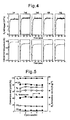
- a thermocouple was installed at the inlet of the catalyst layer and temperature changes were monitored after starting the flow of reaction gas. The time-based changes in catalyst layer inlet temperature following completion of flow of the reaction gas are shown in Fig. 1 , and the temperature of the catalyst layer after 30 minutes is shown in Table 1.
- reaction product at that time was analyzed with a gas chromatograph equipped with a TCD detector (6890N (Agilent Technologies), HP-PLOT Molesieve and HP-PLOT Q).
- TCD detector 6890N (Agilent Technologies), HP-PLOT Molesieve and HP-PLOT Q.
- N 2 was used as an internal standard when calculating n-C 4 H 10 conversion rate and H 2 formation rate. The calculation equations are as shown below (Equation 1).
- the catalysts, reductive activation temperatures, catalyst layer inlet temperatures during the reaction (at the start of the reaction and 30 minutes later) and n-C 4 H 10 conversion rates (after 30 minutes) are shown in Table 1.
- reaction gas was switched to Ar after measuring activity in Reaction Example 1.
- Reduction activation by H 2 was carried out for 1 hour at 800°C followed by cooling to 100°C in the presence of flowing Ar.
- Activity was then measured under conditions consisting of a catalyst layer inlet temperature of 100°C at the start of activity measurement, reaction pressure of 0.1 MPa, molar ratio of n-C 4 H 10 /O 2 /H 2 O/N 2 /Ar of 1/2/4/1/7, total gas feed rate of 555 mL/min and spatial velocity (SV) of 333 L/hr ⁇ g.
- Table 1 The results are shown in Table 1.
- reaction gas was switched to Ar after measuring activity in Reaction Example 2.
- Reduction activation by H 2 was carried out for 1 hour at 800°C followed by cooling to room temperature (36°C) in the presence of flowing Ar.
- Activity was then measured under conditions consisting of a catalyst layer inlet temperature of 36°C at the start of activity measurement, reaction pressure of 0.1 MPa, molar ratio of n-C 4 H 10 /O 2 /N 2 /Ar of 1/2/1/11, total gas feed rate of 555 mL/min and spatial velocity (GHSV) of 333 L/hr ⁇ g.
- Fig. 1 Time-based changes in catalyst layer inlet temperature after starting the flow of reaction gas are shown in Fig. 1 , while the results are shown in Table 1.
- Reactions were carried out using Catalyst Precursor Preparation Examples 1 to 5 in accordance with Reaction Example 1.
- the reductive activation temperature was either 600°C or 800°C.
- the catalyst layer inlet temperature at the start of measuring activity was 32 to 50°C.
- the molar ratio of n-C 4 H 10 /O 2 /N 2 /Ar of the reaction gas was 1/2/1/11, the total gas feed rate was 555 ml/min, and the spatial velocity (GHSV) was 333 L/hr-g.
- the reductive activation temperatures, catalyst layer inlet temperatures at the start of the reaction and the results are shown in Table 2.
- Reactions were carried out using Catalyst Precursor Preparation Example 4 or Catalyst Precursor Preparation Comparative Examples 1 or 2 in accordance with Reaction Example 1.
- the reductive activation temperature was either 600°C or 800°C.
- the catalyst layer inlet temperature at the start of measuring activity was 31 to 48°C.
- the molar ratio of n-C 4 H 10 /O 2 /N 2 /Ar of the reaction gas was 1/2/1/11, the total gas feed rate was 555 ml/min, and the spatial velocity (GHSV) was 333 L/hr-g.
- the reductive activation temperatures, catalyst layer inlet temperatures at the start of the reaction and the results are shown in Table 3.
- Reactions were carried out using Catalyst Precursor Preparation Comparative Examples 1 to 3 in accordance with Reaction Example 1.
- the reductive activation temperature was 800°C.
- Activity was then measured under conditions consisting of a catalyst layer inlet temperature of about 30°C at the start of activity measurement, reaction pressure of 0.1 MPa, molar ratio of n-C 4 H 10 /O 2 /N 2 /Ar of 1/2/4/11, total gas feed rate of 555 mL/min and spatial velocity (GHSV) of 333 L/hr-g.
- GHSV spatial velocity
- a hydrogen production reaction using reforming of hydrocarbon was clearly demonstrated to be able to be driven at normal temperatures or in the vicinity of normal temperatures.
- Catalyst Precursor Preparation Example 1 0.1 g of Catalyst Precursor Preparation Example 1 was filled into an atmospheric pressure fixed bed flow reaction apparatus followed by carrying out reductive activation with pure H 2 at 800°C. The flow gas was switched to Ar (50 mL/min) and the catalyst layer was cooled to room temperature (31°C). The catalyst was then allowed to react with O 2 under conditions consisting of a catalyst layer inlet temperature of 31°C at the start of activity measurement, reaction pressure of 0.1 MPa, molar ratio of O 2 /Ar of 1/4, total gas feed rate of 100 mL/min and spatial velocity (SV) of 60 L/hr-g. A thermocouple was installed at the inlet of the catalyst layer and temperature changes were monitored after starting the flow of reaction gas.
- the catalyst layer inlet temperatures at 0, 2, 4 and 6 minutes after the start of the reaction were 31, 63, 45 and 40°C, and heat was determined to be generated according to Equation 1.
- the following reaction was carried out using an atmospheric pressure fixed bed pulsed-flow reaction apparatus.
- 0.1 g of CeO 2 or Pr 6 O 11 not loaded with Catalyst Precursor Preparation Example 1, Catalyst Precursor Preparation Example 4 or Ni was filled into a metal reaction tube having an outer diameter of 9.9 mm, inner diameter of 7 mm and subjected to deactivation treatment on the inside thereof.
- the temperature was raised to 600 or 800°C (10°C/min) in the presence of flowing pure H 2 (30 mL/min, 0.1 MPa), and the reaction tube was maintained at that temperature for 1 hour to carry out reductive activation treatment.
- the flow gas was then switched to Ar (30 ml/min) and the catalyst layer was cooled to 50°C. 2.88 mL of pure O 2 were then pulsed at that temperature, and the amount of O 2 that remained without being absorbed by the catalyst was quantified with a TCD detector. Hardly any absorption of O 2 was observed by the time of the third pulse for each of the catalysts.
- the catalysts, reductive activation temperatures and total amount of O 2 absorbed up to the second pulse are shown in Table 5.
- Pr 2 O 3 is known to adopt a stable A-type rare earth structure.
- reductive activation was carried out at 600°C, a portion of the oxygen escaped from the Pr 6 O 11 and Pr 6 O 11-y was formed that retained its C-type rare earth structure, and this sample was susceptible to oxidation by oxygen.
- reduction was carried out at a high temperature of 800°C, a portion of the crystal structure changed to an A-type rare earth structure and became stabilized, thereby demonstrating that the n-C 4 H 10 combustion reaction (Reaction Formula 3) and its subsequent reforming reaction (Reaction Formula 4) were unable to be driven as a result of not being oxidized by oxygen at normal temperatures.
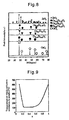
- Catalyst Precursor Preparation Example 1 Even after carrying out reductive activation at both temperatures of 600 and 800°C, metal Ni, NiO (600°C only) and fluorite CeO 2 were observed ( Fig. 3 ). In the case of this catalyst, regardless of which temperature reductive activation is carried out, it was suggested to return to its original structure (CeO 2 ) as a result of being oxidized by air when the sample was transferred to air. Oxygen absorption following the reductive activation at 800°C was further measured for other catalysts using CeO 2 as a support.
- Reactions were carried out using Catalyst Precursor Preparation Examples 2, 3 and 5 in accordance with Reaction Example 1.
- the reductive activation temperature was set to 800°C.
- the catalyst layer inlet temperature at the start of activity measurement was set to 100°C.
- the molar ratio of n-C 4 H 10 /O 2 /H 2 O/N 2 /Ar of the reaction gas was 1/2/4/1/7, the total gas feed rate was 555 mL/min and the spatial velocity (GHSV) was 333 L/hr-g.
- the reductive activation temperatures, catalyst layer inlet temperatures at the start of the reaction and the results are shown in Table 7.
- Reaction Example 13 was carried out in accordance with Reaction Example 1.
- the reductive activation temperature was set to 800°C
- the spatial velocity (GHSV) was set to 167 L/hr-g.
- the catalyst layer inlet temperature at the start of activity measurement was set to 50°C.
- the molar ratio of n-C 4 H 10 /O 2 /N 2 /Ar of the reaction gas was 1/2/1/11, and the total gas feed rate was 555 mL/min.
- analysis using a mass spectrometer (M-201QA-TDM (Canon Anelva)) was carried out in addition to analysis of the product by gas chromatography.
- O 2 ⁇ conversion rate % Volumetric concentration of O 2 at reaction tube inlet - volumetric concentration of O 2 at reaction tube outlet ⁇ ⁇ Volumetric concentration of O 2 at reaction tube inlet ⁇ 100
- CO yield % Volumetric concentration of CO at reaction tube outlet ⁇ ⁇ Volumetric concentration of C 4 ⁇ H 10 at reaction tube inlet ⁇ 4 ⁇ 100
- CO 2 yield % Volumetric concentration of CO 2 at reaction tube outlet ⁇ Volumetric concentration of C 4 ⁇ H 10 at reaction tube inlet ⁇ 4 ⁇ 100
- CH ⁇ 4 yield % Volumetric concentration of CH 4 at reaction tube outlet ⁇ ⁇ Volumetric concentration of C 4 ⁇ H 10 at reaction tube inlet ⁇ 4 ⁇ 100 As shown in Fig.
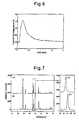
- Catalyst Precursor Preparation Example 3 was reduced at 800°C followed by passing a gas at a molar ratio of O 2 /Ar/N 2 of 2/12/1 over the catalyst at 50°C. Temperature changes within the catalyst layer at that time are shown in Fig. 6 .
- Catalyst Precursor Preparation Example 3 was measured by in situ XRD either after treating the catalyst by passing over H 2 /He (5/95) at 800°C or by treating with an air flow as is. The results are shown in Fig. 7 .
- a hexagonal fluorite structure was only observed for the XRD patterns measured at 800°C regardless of the type of treatment.
- Reaction Example 14 was carried out using Catalyst Precursor Preparation Example 6 in accordance with Reaction Example 1. Temperature changes within the catalyst layer were measured by using a quartz reaction tube and inserting a thermocouple into the catalyst layer. The reductive activation temperature was set to 600°C. The catalyst layer temperature at the start of activity measurement was set to 50°C. The reaction gas consisted of n-C 4 H 10 /O 2 /N 2 /Ar at a molar ratio of 1/2/1/7, the total gas feed rate was 407 mL/min, and the spatial velocity (GHSV) was 244 L/hr-g. The reductive activation temperature, catalyst layer inlet temperature at the start of the reaction and the results are shown in Table 8.
- Reaction Example 15 was carried out using Catalyst Precursor Preparation Example 7 in accordance with Reaction Example 1. Temperature changes within the catalyst layer were measured by using a quartz reaction tube and inserting a thermocouple into the catalyst layer. The reductive activation temperature was set to 200°C. The catalyst layer temperature at the start of activity measurement was set to 50°C. The reaction gas consisted of n-C 4 H 10 /O 2 /N 2 /Ar at a molar ratio of 1/2/1/7, the total gas feed rate was 407 mL/min, and the spatial velocity (GHSV) was 244 L/hr-g. The reaction was stopped by switching the reaction gas to Ar after carrying out the reaction for 40 minutes. Reaction Example 16 was then carried out under the same conditions as those following the reductive activation by again adjusting the catalyst layer temperature to 50°C. The reductive activation temperatures, catalyst layer inlet temperatures at the start of the reaction and the results are shown in Table 8.
- Reaction Example 17 was carried out using Catalyst Precursor Preparation Example 8 in accordance with Reaction Example 1. Temperature changes within the catalyst layer were measured by using a quartz reaction tube and inserting a thermocouple into the catalyst layer. The reductive activation temperature was set to 100°C. The catalyst layer temperature at the start of activity measurement was set to 50°C. The reaction gas consisted of n-C 4 H 10 /O 2 /N 2 /Ar at a molar ratio of 1/2/1/7, the total gas feed rate was 407 mL/min, and the spatial velocity (GHSV) was 244 L/hr-g. The reaction was stopped by switching the reaction gas to Ar after carrying out the reaction for 40 minutes. Reaction Example 18 was then carried out under the same conditions as those following the reductive activation by again adjusting the catalyst layer temperature to 50°C. The reductive activation temperatures, catalyst layer inlet temperatures at the start of the reaction and the results are shown in Table 8.
- Reaction Example 19 was carried out using Catalyst Precursor Preparation Example 9 in accordance with Reaction Example 1. Temperature changes within the catalyst layer were measured by using a quartz reaction tube and inserting a thermocouple into the catalyst layer. The reductive activation temperature was set to 100°C. The catalyst layer temperature at the start of activity measurement was set to 50°C. The reaction gas consisted of n-C 4 H 10 /O 2 /N 2 /Ar at a molar ratio of 1/2/1/7, the total gas feed rate was 407 mL/min, and the spatial velocity (GHSV) was 244 L/hr-g. The reaction was stopped by switching the reaction gas to Ar after carrying out the reaction for 40 minutes. Reaction Example 20 was then carried out under the same conditions as those following the reductive activation by again adjusting the catalyst layer temperature to 50°C. The reductive activation temperatures, catalyst layer inlet temperatures at the start of the reaction and the results are shown in Table 8.
- Reaction Example 21 was carried out using Catalyst Precursor Preparation Example 10 in accordance with Reaction Example 1. Temperature changes within the catalyst layer were measured by using a quartz reaction tube and inserting a thermocouple into the catalyst layer. The reductive activation temperature was set to 200°C. The catalyst layer temperature at the start of activity measurement was set to 50°C. The reaction gas consisted of n-C 4 H 10 /O 2 /N 2 /Ar at a molar ratio of 1/2/1/7, the total gas feed rate was 407 mL/min, and the spatial velocity (GHSV) was 244 L/hr-g. The reductive activation temperature, catalyst layer inlet temperature at the start of the reaction and the results are shown in Table 8.
- Reaction Example 22 was carried out using Catalyst Precursor Preparation Example 11 in accordance with Reaction Example 1. Temperature changes within the catalyst layer were measured by using a quartz reaction tube and inserting a thermocouple into the catalyst layer. The reductive activation temperature was set to 600°C. The catalyst layer temperature at the start of activity measurement was set to 50°C. The reaction gas consisted of n-C 4 H 10 /O 2 /N 2 /Ar at a molar ratio of 1/2/1/7, the total gas feed rate was 407 mL/min, and the spatial velocity (GHSV) was 244 L/hr-g. The reductive activation temperature, catalyst layer inlet temperature at the start of the reaction and the results are shown in Table 8.
- Reaction Example 23 was carried out using Catalyst Precursor Preparation Example 12 in accordance with Reaction Example 1. Temperature changes within the catalyst layer were measured by using a quartz reaction tube and inserting a thermocouple into the catalyst layer. The reductive activation temperature was set to 400°C. The catalyst layer temperature at the start of activity measurement was set to 50°C. The reaction gas consisted of n-C 4 H 10 /O 2 /N 2 /Ar at a molar ratio of 1/2/1/7, the total gas feed rate was 407 mL/min, and the spatial velocity (GHSV) was 244 L/hr-g. The reaction was stopped by switching the reaction gas to Ar after carrying out the reaction for 40 minutes. Reaction Example 24 was then carried out under the same conditions as those following the reductive activation by again adjusting the catalyst layer temperature to 50°C. The reductive activation temperatures, catalyst layer inlet temperatures at the start of the reaction and the results are shown in Table 8.
- Reaction Example 25 was carried out using Catalyst Precursor Preparation Example 13 in accordance with Reaction Example 1. Temperature changes within the catalyst layer were measured by using a quartz reaction tube and inserting a thermocouple into the catalyst layer. The reductive activation temperature was set to 100°C. The catalyst layer temperature at the start of activity measurement was set to 50°C. The reaction gas consisted of n-C 4 H 10 /O 2 /N 2 /Ar at a molar ratio of 1/2/1/7, the total gas feed rate was 407 mL/min, and the spatial velocity (GHSV) was 244 L/hr-g. The reductive activation temperature, catalyst layer inlet temperature at the start of the reaction and the results are shown in Table 8.
- reaction Example 26 was then carried out under the same conditions as those following the reductive activation by again adjusting the catalyst layer temperature to 50°C.
- the reductive activation temperature, catalyst layer inlet temperature at the start of the reaction and the results are shown in Table 8.
- Reaction Comparative Example 9 was carried out using Catalyst Precursor Preparation Comparative Example 4 in accordance with Reaction Example 1. Temperature changes within the catalyst layer were measured by using a quartz reaction tube and inserting a thermocouple into the catalyst layer. The reductive activation temperature was set to 800°C. The catalyst layer temperature at the start of activity measurement was set to 50°C. The reaction gas consisted of n-C 4 H 10 /O 2 /N 2 /Ar at a molar ratio of 1/2/1/7, the total gas feed rate was 407 mL/min, and the spatial velocity (GHSV) was 244 L/hr-g. The reductive activation temperature, catalyst layer inlet temperature at the start of the reaction and the results are shown in Table 9.
- Reaction Example 27 was carried out using Catalyst Precursor Preparation Example 3 in accordance with Reaction Example 1.
- a U-shaped quartz reaction tube was used.
- the reductive activation temperature was set to 800°C.
- the catalyst layer became red hot from the moment the reaction gas was supplied and the reaction was determined to be driven by the heat.
- the predicted experiment results are shown in Table 10.
- Reactions were carried out using Catalyst Precursor Preparation Example 3 in accordance with Reaction Example 1. Temperature changes within the catalyst layer were measured by using a quartz reaction tube and inserting a thermocouple into the catalyst layer. The reductive activation temperature was set to 600°C. In addition, aluminum balls (Nikkato Corp., diameter: 1 mm) were adequately filled in front of and behind the catalyst layer.
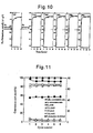
- Reaction Example 29 was carried out under the same conditions as those following the reductive activation (catalyst layer temperature at start of activity measurement: 38°C). Reaction Examples 30 to 33 were subsequently carried out by repeating the procedure of reacting for 30 minutes, cooling in Ar and reacting starting from room temperature. The results are shown in Table 11.
- Hydrogen production by hydrocarbon reforming has had the problem of the temperature for driving the reaction being 200°C or higher due to being unable to realize a self-sufficient on-site reforming fuel cell system that does not require energy to be supplied from the outside.
- the present invention provides a method for driving hydrogen production reactions at normal temperatures, and contributes to the realization of hydrogen stations, fuel cell vehicles loaded with gasoline and the like by utilizing the heat and H 2 generated in these reactions, thereby having a large potential for future use.
Landscapes
- Chemical & Material Sciences (AREA)
- Chemical Kinetics & Catalysis (AREA)
- Organic Chemistry (AREA)
- Engineering & Computer Science (AREA)
- Materials Engineering (AREA)
- General Health & Medical Sciences (AREA)
- Health & Medical Sciences (AREA)
- Combustion & Propulsion (AREA)
- Inorganic Chemistry (AREA)
- Manufacturing & Machinery (AREA)
- Sustainable Development (AREA)
- Sustainable Energy (AREA)
- Electrochemistry (AREA)
- General Chemical & Material Sciences (AREA)
- Life Sciences & Earth Sciences (AREA)
- Catalysts (AREA)
- Hydrogen, Water And Hydrids (AREA)
Applications Claiming Priority (2)
| Application Number | Priority Date | Filing Date | Title |
|---|---|---|---|
| JP2007222834A JP5428103B2 (ja) | 2007-02-21 | 2007-08-29 | 低温水素製造用触媒及びその製造方法と水素製造方法 |
| PCT/JP2007/072395 WO2009028113A1 (ja) | 2007-08-29 | 2007-11-19 | 低温水素製造用触媒及びその製造方法と水素製造方法 |
Publications (2)
| Publication Number | Publication Date |
|---|---|
| EP2184104A1 true EP2184104A1 (de) | 2010-05-12 |
| EP2184104A4 EP2184104A4 (de) | 2017-08-23 |
Family
ID=39903027
Family Applications (1)
| Application Number | Title | Priority Date | Filing Date |
|---|---|---|---|
| EP07832125.4A Withdrawn EP2184104A4 (de) | 2007-08-29 | 2007-11-19 | Katalysator für die herstellung von wasserstoff bei niedriger temperatur, verfahren zur herstellung des katalysators und verfahren zur herstellung von wasserstoff |
Country Status (2)
| Country | Link |
|---|---|
| EP (1) | EP2184104A4 (de) |
| WO (1) | WO2009028113A1 (de) |
Families Citing this family (6)
| Publication number | Priority date | Publication date | Assignee | Title |
|---|---|---|---|---|
| WO2011075845A1 (en) * | 2009-12-22 | 2011-06-30 | Airscience Technologies | System and process for the production of hydrogen from raw gas using a nanoparticle ceria based catalyst |
| JP5580626B2 (ja) * | 2010-03-05 | 2014-08-27 | Dowaホールディングス株式会社 | 水素製造用触媒、水素製造用触媒の製造方法、水素製造方法、水素製造装置及び燃料電池システム |
| US20130058861A1 (en) | 2010-03-05 | 2013-03-07 | University Of Regina | Catalysts for feedstock-flexible and process-flexible hydrogen production |
| JP6168519B2 (ja) * | 2013-09-10 | 2017-07-26 | Dowaホールディングス株式会社 | 触媒、触媒の製造方法、水素含有ガスの製造方法、水素製造装置および燃料電池システム |
| JP2015150486A (ja) * | 2014-02-13 | 2015-08-24 | Jx日鉱日石エネルギー株式会社 | 水素製造用触媒、水素製造用触媒の製造方法及び水素製造方法 |
| CN117299135B (zh) * | 2023-08-18 | 2025-08-22 | 华南农业大学 | 一种双缺陷Ni/NiOx@C催化剂及其制备方法与在光热辅助光催化制氢中的应用 |
Family Cites Families (10)
| Publication number | Priority date | Publication date | Assignee | Title |
|---|---|---|---|---|
| EP0582004B1 (de) * | 1992-07-29 | 1997-01-29 | Council of Scientific and Industrial Research | Katalysatoren und ihre Verwendung bei der oxydativen Umwandlung von Methan oder von Erdgas zu Synthesegas |
| EP1013603A1 (de) * | 1998-12-22 | 2000-06-28 | Haldor Topsoe A/S | Verfahren zur katalytischen Dampfreformieung eines Kohlenwasserstoffeinsatzes |
| JP4648567B2 (ja) * | 2001-05-11 | 2011-03-09 | Jx日鉱日石エネルギー株式会社 | オートサーマルリフォーミング触媒および燃料電池用燃料ガスの製造方法 |
| GB0115850D0 (en) * | 2001-06-28 | 2001-08-22 | Isis Innovations Ltd | Catalyst |
| US20050153835A1 (en) * | 2002-03-29 | 2005-07-14 | Yoshitaka Uchida | Modification catalyst composition |
| JP3885139B2 (ja) * | 2003-10-28 | 2007-02-21 | 財団法人地球環境産業技術研究機構 | エタノール水蒸気改質触媒、その製造方法及び水素の製造方法 |
| JP2005296755A (ja) * | 2004-04-08 | 2005-10-27 | Nippon Oil Corp | 水蒸気改質触媒、水蒸気改質方法、水素製造装置および燃料電池システム |
| JP2006167501A (ja) * | 2004-12-13 | 2006-06-29 | Matsushita Electric Ind Co Ltd | 改質触媒、水素生成装置および燃料電池システム |
| JP4767543B2 (ja) | 2005-01-07 | 2011-09-07 | Jx日鉱日石エネルギー株式会社 | 固体酸化物形燃料電池システムの起動方法 |
| JP4724860B2 (ja) * | 2005-10-19 | 2011-07-13 | 国立大学法人 大分大学 | 水素製造用触媒の製造方法 |
-
2007
- 2007-11-19 EP EP07832125.4A patent/EP2184104A4/de not_active Withdrawn
- 2007-11-19 WO PCT/JP2007/072395 patent/WO2009028113A1/ja not_active Ceased
Non-Patent Citations (1)
| Title |
|---|
| See references of WO2009028113A1 * |
Also Published As
| Publication number | Publication date |
|---|---|
| EP2184104A4 (de) | 2017-08-23 |
| WO2009028113A1 (ja) | 2009-03-05 |
Similar Documents
| Publication | Publication Date | Title |
|---|---|---|
| US9073043B2 (en) | Hydrogen production catalyst, production method of the same and hydrogen production method | |
| Yabe et al. | Low-temperature dry reforming of methane to produce syngas in an electric field over La-doped Ni/ZrO2 catalysts | |
| Roh et al. | Methane-reforming reactions over Ni/Ce-ZrO2/θ-Al2O3 catalysts | |
| Mateos-Pedrero et al. | CuO/ZnO catalysts for methanol steam reforming: The role of the support polarity ratio and surface area | |
| Busca et al. | Nickel versus cobalt catalysts for hydrogen production by ethanol steam reforming: Ni–Co–Zn–Al catalysts from hydrotalcite-like precursors | |
| Haynes et al. | Catalytic partial oxidation of n-tetradecane using pyrochlores: Effect of Rh and Sr substitution | |
| RU2680060C1 (ru) | Способ риформинга смесей из углеводородов и диоксида углерода | |
| US7824656B2 (en) | Catalysts for hydrogen production | |
| Shang et al. | Enhanced low-temperature activity for CO2 methanation over Ru doped the Ni/CexZr (1− x) O2 catalysts prepared by one-pot hydrolysis method | |
| DK1406725T3 (en) | Perovskites comprising noble metals and their use as catalysts | |
| Song et al. | Effect of synthesis parameters on the catalytic activity of Co–ZrO 2 for bio-ethanol steam reforming | |
| US9675962B2 (en) | Perovskite-type strontium titanate | |
| CN102802789B (zh) | 烃类气体重整用催化剂、其制造方法及合成气体的制造方法 | |
| Ruocco et al. | Methane dry reforming on Ru perovskites, AZrRuO3: Influence of preparation method and substitution of A cation with alkaline earth metals | |
| EP2184104A1 (de) | Katalysator für die herstellung von wasserstoff bei niedriger temperatur, verfahren zur herstellung des katalysators und verfahren zur herstellung von wasserstoff | |
| Cao et al. | Autothermal reforming of methane over Rh/Ce0. 5Zr0. 5O2 catalyst: Effects of the crystal structure of the supports | |
| AU2022293970A1 (en) | Method for producing catalysts for high temperature chemical processes and catalysts thus obtained. | |
| Roselin et al. | Production of hydrogen by oxidative steam reforming of methanol over Cu/SiO2 catalysts | |
| Xie et al. | Autothermal reforming and partial oxidation of n-hexadecane via Pt/Ni bimetallic catalysts on ceria-based supports | |
| Dongare et al. | Oxidation activity and 18O-isotope exchange behavior of nickel oxide-stabilized cubic zirconia | |
| Song et al. | Effect of the Zr/Al molar ratio on the performance of Cu/ZrO2–Al2O3 catalysts for methanol steam reforming | |
| Ghodke et al. | Effect of B site substitution in Gd2B2-xNiyO7-δ (B= Ti, Zr) ternary metal oxide catalysts in dry reforming of methane | |
| Álvarez-Galván et al. | Surface reactivity of LaCoO3 and Ru/LaCoO3 towards CO, CO2 and C3H8: Effect of H2 and O2 pretreatments | |
| Viparelli et al. | Catalyst based on BaZrO3 with different elements incorporated in the structure: II. BaZr (1− x) RhxO3 systems for the production of syngas by partial oxidation of methane | |
| Johansson et al. | Characterization of LaRhO3 perovskites for dry (CO2) reforming of methane (DRM) |
Legal Events
| Date | Code | Title | Description |
|---|---|---|---|
| PUAI | Public reference made under article 153(3) epc to a published international application that has entered the european phase |
Free format text: ORIGINAL CODE: 0009012 |
|
| 17P | Request for examination filed |
Effective date: 20100226 |
|
| AK | Designated contracting states |
Kind code of ref document: A1 Designated state(s): AT BE BG CH CY CZ DE DK EE ES FI FR GB GR HU IE IS IT LI LT LU LV MC MT NL PL PT RO SE SI SK TR |
|
| AX | Request for extension of the european patent |
Extension state: AL BA HR MK RS |
|
| DAX | Request for extension of the european patent (deleted) | ||
| RA4 | Supplementary search report drawn up and despatched (corrected) |
Effective date: 20160819 |
|
| RIC1 | Information provided on ipc code assigned before grant |
Ipc: C01B 3/38 20060101ALI20160812BHEP Ipc: H01M 8/06 20060101ALI20160812BHEP Ipc: B01J 23/76 20060101AFI20160812BHEP Ipc: B01J 23/63 20060101ALI20160812BHEP |
|
| DA4 | Supplementary search report drawn up and despatched (deleted) | ||
| RIC1 | Information provided on ipc code assigned before grant |
Ipc: H01M 8/06 20160101ALI20170621BHEP Ipc: C01B 3/38 20060101ALI20170621BHEP Ipc: B01J 23/63 20060101ALI20170621BHEP Ipc: B01J 23/76 20060101AFI20170621BHEP |
|
| RA4 | Supplementary search report drawn up and despatched (corrected) |
Effective date: 20170721 |
|
| STAA | Information on the status of an ep patent application or granted ep patent |
Free format text: STATUS: THE APPLICATION IS DEEMED TO BE WITHDRAWN |
|
| 18D | Application deemed to be withdrawn |
Effective date: 20171019 |