EP2184147A2 - Dispositif destiné à couper un boudin de matériau plastique, doté d'au moins un dispositif de réglage pour déplacer au moins un élément de support pour une section longitudinale de boudin sectionnée - Google Patents
Dispositif destiné à couper un boudin de matériau plastique, doté d'au moins un dispositif de réglage pour déplacer au moins un élément de support pour une section longitudinale de boudin sectionnée Download PDFInfo
- Publication number
- EP2184147A2 EP2184147A2 EP09174631A EP09174631A EP2184147A2 EP 2184147 A2 EP2184147 A2 EP 2184147A2 EP 09174631 A EP09174631 A EP 09174631A EP 09174631 A EP09174631 A EP 09174631A EP 2184147 A2 EP2184147 A2 EP 2184147A2
- Authority
- EP
- European Patent Office
- Prior art keywords
- cutting
- passage
- strand
- notching
- adjustment
- Prior art date
- Legal status (The legal status is an assumption and is not a legal conclusion. Google has not performed a legal analysis and makes no representation as to the accuracy of the status listed.)
- Granted
Links
- 238000005520 cutting process Methods 0.000 title claims abstract description 219
- 239000000463 material Substances 0.000 title claims description 11
- 230000033001 locomotion Effects 0.000 claims description 69
- 239000007787 solid Substances 0.000 claims description 5
- 238000003466 welding Methods 0.000 claims description 4
- 239000004927 clay Substances 0.000 claims description 3
- 239000011796 hollow space material Substances 0.000 claims description 3
- 238000011144 upstream manufacturing Methods 0.000 description 33
- 238000010276 construction Methods 0.000 description 20
- 238000003892 spreading Methods 0.000 description 13
- 230000007480 spreading Effects 0.000 description 13
- 238000004519 manufacturing process Methods 0.000 description 4
- 238000006073 displacement reaction Methods 0.000 description 3
- 239000011449 brick Substances 0.000 description 2
- 230000006872 improvement Effects 0.000 description 2
- 238000000034 method Methods 0.000 description 2
- 238000000465 moulding Methods 0.000 description 2
- 230000002441 reversible effect Effects 0.000 description 2
- TVEXGJYMHHTVKP-UHFFFAOYSA-N 6-oxabicyclo[3.2.1]oct-3-en-7-one Chemical compound C1C2C(=O)OC1C=CC2 TVEXGJYMHHTVKP-UHFFFAOYSA-N 0.000 description 1
- 230000009471 action Effects 0.000 description 1
- 230000001154 acute effect Effects 0.000 description 1
- 229910052782 aluminium Inorganic materials 0.000 description 1
- XAGFODPZIPBFFR-UHFFFAOYSA-N aluminium Chemical compound [Al] XAGFODPZIPBFFR-UHFFFAOYSA-N 0.000 description 1
- 230000009286 beneficial effect Effects 0.000 description 1
- 230000002457 bidirectional effect Effects 0.000 description 1
- 230000001419 dependent effect Effects 0.000 description 1
- 238000011161 development Methods 0.000 description 1
- 230000018109 developmental process Effects 0.000 description 1
- 238000001035 drying Methods 0.000 description 1
- 230000000694 effects Effects 0.000 description 1
- 230000002349 favourable effect Effects 0.000 description 1
- 238000010304 firing Methods 0.000 description 1
- 238000002789 length control Methods 0.000 description 1
- 238000003754 machining Methods 0.000 description 1
- 229910052751 metal Inorganic materials 0.000 description 1
- 239000002184 metal Substances 0.000 description 1
- 238000003801 milling Methods 0.000 description 1
- 230000000149 penetrating effect Effects 0.000 description 1
- 230000002093 peripheral effect Effects 0.000 description 1
- 230000006641 stabilisation Effects 0.000 description 1
- 238000011105 stabilization Methods 0.000 description 1
- 239000013585 weight reducing agent Substances 0.000 description 1
Images





Classifications
-
- B—PERFORMING OPERATIONS; TRANSPORTING
- B28—WORKING CEMENT, CLAY, OR STONE
- B28B—SHAPING CLAY OR OTHER CERAMIC COMPOSITIONS; SHAPING SLAG; SHAPING MIXTURES CONTAINING CEMENTITIOUS MATERIAL, e.g. PLASTER
- B28B11/00—Apparatus or processes for treating or working the shaped or preshaped articles
- B28B11/14—Apparatus or processes for treating or working the shaped or preshaped articles for dividing shaped articles by cutting
- B28B11/16—Apparatus or processes for treating or working the shaped or preshaped articles for dividing shaped articles by cutting for extrusion or for materials supplied in long webs
-
- B—PERFORMING OPERATIONS; TRANSPORTING
- B26—HAND CUTTING TOOLS; CUTTING; SEVERING
- B26D—CUTTING; DETAILS COMMON TO MACHINES FOR PERFORATING, PUNCHING, CUTTING-OUT, STAMPING-OUT OR SEVERING
- B26D1/00—Cutting through work characterised by the nature or movement of the cutting member or particular materials not otherwise provided for; Apparatus or machines therefor; Cutting members therefor
- B26D1/01—Cutting through work characterised by the nature or movement of the cutting member or particular materials not otherwise provided for; Apparatus or machines therefor; Cutting members therefor involving a cutting member which does not travel with the work
- B26D1/547—Cutting through work characterised by the nature or movement of the cutting member or particular materials not otherwise provided for; Apparatus or machines therefor; Cutting members therefor involving a cutting member which does not travel with the work having a wire-like cutting member
- B26D1/553—Cutting through work characterised by the nature or movement of the cutting member or particular materials not otherwise provided for; Apparatus or machines therefor; Cutting members therefor involving a cutting member which does not travel with the work having a wire-like cutting member with a plurality of wire-like cutting members
-
- B—PERFORMING OPERATIONS; TRANSPORTING
- B28—WORKING CEMENT, CLAY, OR STONE
- B28B—SHAPING CLAY OR OTHER CERAMIC COMPOSITIONS; SHAPING SLAG; SHAPING MIXTURES CONTAINING CEMENTITIOUS MATERIAL, e.g. PLASTER
- B28B11/00—Apparatus or processes for treating or working the shaped or preshaped articles
- B28B11/08—Apparatus or processes for treating or working the shaped or preshaped articles for reshaping the surface, e.g. smoothing, roughening, corrugating, making screw-threads
- B28B11/0863—Apparatus or processes for treating or working the shaped or preshaped articles for reshaping the surface, e.g. smoothing, roughening, corrugating, making screw-threads for profiling, e.g. making grooves
-
- B—PERFORMING OPERATIONS; TRANSPORTING
- B28—WORKING CEMENT, CLAY, OR STONE
- B28B—SHAPING CLAY OR OTHER CERAMIC COMPOSITIONS; SHAPING SLAG; SHAPING MIXTURES CONTAINING CEMENTITIOUS MATERIAL, e.g. PLASTER
- B28B11/00—Apparatus or processes for treating or working the shaped or preshaped articles
- B28B11/14—Apparatus or processes for treating or working the shaped or preshaped articles for dividing shaped articles by cutting
- B28B11/16—Apparatus or processes for treating or working the shaped or preshaped articles for dividing shaped articles by cutting for extrusion or for materials supplied in long webs
- B28B11/163—Apparatus or processes for treating or working the shaped or preshaped articles for dividing shaped articles by cutting for extrusion or for materials supplied in long webs in which the cutting device is moved longitudinally with the moving strand
- B28B11/165—Apparatus or processes for treating or working the shaped or preshaped articles for dividing shaped articles by cutting for extrusion or for materials supplied in long webs in which the cutting device is moved longitudinally with the moving strand mounted on a carrier
-
- B—PERFORMING OPERATIONS; TRANSPORTING
- B26—HAND CUTTING TOOLS; CUTTING; SEVERING
- B26D—CUTTING; DETAILS COMMON TO MACHINES FOR PERFORATING, PUNCHING, CUTTING-OUT, STAMPING-OUT OR SEVERING
- B26D7/00—Details of apparatus for cutting, cutting-out, stamping-out, punching, perforating, or severing by means other than cutting
- B26D7/01—Means for holding or positioning work
Definitions
- the invention relates to a device for cutting a strand of plastic material, with at least one adjusting device for adjusting at least one support member for a cut strand longitudinal section.
- a device of this type can be cut from a strand of plastic material moldings in the form of longitudinal sections, the z. B. have reached their final production state in their plastic state and z. B. can be packaged or further processed, for. B. by drying or firing, as is the case in the manufacture of components, especially bricks, for the construction industry.
- a device of the aforementioned type is in the DE 10 2005 021 038 A1 described.
- This known device may have a notching device for attaching notches on the circumference of the strand in a different construction.
- one-piece notching strips are provided in the sense of wedges, which are arranged offset with respect to a cutting device in the longitudinal direction of the conveying passage.
- the notching strips are formed by two so-called chamfering strips, which have a distance directed along the passage from each other, wherein the cutting wire of the cutting device is movable transversely through the passage between the chamfering strips.
- the notching and cutting occur during the passage of the strand, the cutting device and the notching device being advanced with the strand, and after the notching and cutting, the return movement of the cutting device and the notching device to the rear.
- the cutting wire for cutting the strand can always be moved from one side of the passage to the other side and each after an adjustment to the front of the truncated strand longitudinal section supporting support member are moved back in an idle stroke by the spread kerf (monodirectional cutting). By spreading the kerf clamping of the cutting wire in the kerf be avoided or at least reduced.
- the aforementioned adjustment is carried out in each case by a support member adjustment device whose construction and function is based on a considerable mechanical effort and expenditure of time, when several notching and cutting devices are arranged along the passage one behind the other. It should be noted that short designs are desirable in order to cut relatively short strand longitudinal sections.
- the invention has for its object to find a space-favorable construction for the device, in particular in the field of adjustment.
- a small and in particular narrow or short support member construction is desired in order to be able to cut relatively short strand longitudinal sections in a simple manner.
- the support member adjustment between a truncated strand longitudinal section bearing support member and a support member carrying cross member is effective.
- the construction of the adjustment can be limited to the area and thus on a small area of the support member, so that the cross member is structurally free in its other lateral areas.
- the cross member can be in the area between the support member and the cross member a simple and stable construction small or short size realize whose function is very beneficial.
- a guide for the spreading movement and / or an adjustment can be realized in a structurally favorable manner, preferably on both sides of a vertical longitudinal center plane of the conveying passage.
- the z. B. may be formed by a return spring, which is stretched by the adjustment or additionally tensioned.
- a cutting wire adjustment device is associated with the holders of the cutting wire so that the cutting wire is adjustable and recoverable in the longitudinal direction of the conveying passage.
- This Verstellsten can be low, z. B. only about 1 mm to 3 mm, in particular about 2 mm, whereby a sufficient distance of the cutting wire is achieved by the relevant cutting surface.
- a cutting wire adjustment device per se is in the DE 102 57 192 A1 described.
- the invention is particularly suitable for a device in which a plurality of notching devices, cutting devices and transverse slots are arranged longitudinally one behind the other.
- a plurality of support members arranged one behind the other are adjustable by adjustment devices according to the invention, whereby the length of the adjustment movement increases with the number of supporting parts to be adjusted.
- the achievable simplification consists inter alia in that the adjusting devices differ only by stops of different lengths, which can be used selectively to achieve different and desired movement lengths.
- a present device particularly in the area in which the strand is notched and cut, requires a construction which, despite its permissive mobility, is stable or provides stable support for the notching devices.
- the at least one notching device and the cutting device are mounted on a support frame surrounding the conveyor passage in the form of a plate arranged at an edge on one broadside thereof.
- the cross member (24) has a longitudinal adjustment guide (26), in which the support member (20) is slidably mounted back and forth.
- the adjustment guide (26a) has pairs of guide elements arranged on both sides of the longitudinal axis (2a) of the passage (2).
- the pairs of guide elements are each formed by a guide hole (26d) and a guide pin (26c) mounted displaceably therein.
- the support member adjustment device (26) has a push or pull element and a return element.
- the push or pull element by a piston or a cylinder one, z.
- hydraulic, pneumatic or electric, drivable piston-cylinder drive formed in one or two opposite adjustment directions (28) is effective.
- the support member adjustment device (26) has a spring (27) for moving the support part (20) forward or backward.
- the adjusting movement is limited by a stop (A).
- the cutting device has at least one notching device (5) with at least one notched bar (5b, 5c, 5d) for transversely directed notches of the strand (3) on at least one of its sides, wherein the at least one notched bar (5b, 5c, 5d) a notch drive (18) is mounted transversely movable between a notch initial position and a notched position.
- the notching device (5) is arranged on a supporting frame (9a) surrounding the conveying passage (2).
- the support frame (9a) by an adjusting device (26), preferably simultaneously as the support member (20), longitudinally adjustable and back adjustable.
- the support frame (9a) by the support member adjustment device (26) adjustable.
- the support frame (9a) is mounted and fixed on or on the web or webs (20b).
- the support frame (9a) in the form of an upside-down U.
- the invention is further based on the object to stabilize a device specified in the preamble of claim 10 way and to improve the design.
- the support frame at least at its lateral inner edges and at its upper inner edge in each case a plate-shaped web wall which is arranged parallel to the central axis of the conveying passage and extends in the circumferential direction of the conveying passage, wherein the mutually facing ends of the web walls are interconnected ,
- this embodiment of the invention is a stable construction, because the extension of the web walls directed in the longitudinal direction of the device in combination with the quadrangular shape results in a stable frame construction.
- the support frame with the three web walls in the form of an inverted U can be closed at the bottom by a fourth web wall or connected by a one-piece or multi-piece cross member to a closed frame.
- the at least one notching strip or two laterally opposite notching strips or else an upper notching strip and optionally also a lower notching strip are preferably arranged inside of the associated frame sections or web walls and thus in the cavity of the passage of the support frame, resulting in a short construction.
- the notch drive is arranged at least partially in the hollow space of the hollow profiles.
- the inventive design leads to a mechanical protection function for the notch drive, since this is at least partially surrounded by legs of the associated hollow profile.
- the legs are preferably directed transversely to the passage direction to the outside, wherein the notch drive is arranged at least partially recessed in the cavity between the legs.
- the drive connection between the notch drive and the Anfasangn or a common Anfasangn support for it can be done through holes in the web of the U-profile.
- the web walls (9f) are formed by hollow sections of approximately quadrangular cross-section, e.g. formed by U-profiles.
- the mutually circumferentially facing ends of the frame parts (9b, 9c, 9d) are mitred and the web walls (9f) are joined together, e.g. by welding.
- the at least one notch drive (18) is arranged at least partially in the hollow space of the hollow profile.
- the frame parts (9b, 9c, 9d) solid profiles and the web walls (9f) formed by externally open recesses (51) in the solid sections.
- the notching device (5) has two opposite, in particular laterally opposite, notching strips (5b, 5c), or also an upper notching strip (5d) or notching strips (5b, 5c, 5d, 5e) on all four sides.
- a plurality of cutting devices (4) and preferably also notching devices (5) are provided, which are arranged in a longitudinal direction of the passage (2) directed distance (a) from each other, and the conveyor (1a) corresponding to a plurality of transverse slots (20a).
- the notching devices (5) arranged in a transverse plane (E) are arranged on a support frame (9a) surrounding the passage (2) and the support frame (9a) or a plurality of support frames (9a) arranged longitudinally behind one another forms a structural unit (B).
- the notched bars (5a) associated with a common transverse plane (E1 to E5) are each formed by two chamfering strips (15) extending in the circumferential direction of the passage (2) and spaced (a) from each other along the passageway (2) in that a cutting wire (4a) of the cutting device (5) is movable transversely through the passage (3) between the chamfering strips (15).
- three or more support frames (9) along the passage (2) arranged one behind the other, of which the initial frame (Ma) carries the back Anfasraun (15) of the first Anfasraunpove in the region of its front, the next center frame (Mm) in the region of its back the front chamfer strips of the first chamfer strip pairs and in the region of its front side the back chamfer strips of the second chamfer strip pairs, and the next support frame or end frame (Me) in the region of its back carries the front chamfers of the associated chamfer strip pairs.
- the cutting direction is directed approximately vertically, in particular from top to bottom.
- the transverse guide (22) for the holders (21) on both sides of the passage (2) on an approximately vertical guide element indirectly or is directly connected to the cross member (24), wherein the upper ends of the guide elements by a transverse bar (23) are interconnected.
- the cutting device (4) in each case a cutting wire (4a) and the cutting device (4) or a plurality of cutting devices (4) each have a wire adjusting device (31) to the along the conveyor passage (2) directed adjustment of the cutting wire (4a).
- each holder (21) has a wire adjusting device (31).
- the adjusting devices (31) are each formed by a thrust member which is arranged on the inside of the associated holder (21) and against the cutting wire (4a) can be pressed.
- the thrust members are each mounted on a holding arm (21b) which is directly or indirectly attached to the associated holder (21) and extends in an along the passage (2) offset arrangement inwardly and the thrust member in a holder (21) carries inside towering area.
- the support member adjustment device (26) in each case the cutting wire (4a1) of the rearmost cutting device (4.1) or the cutting wire (4a2) of the second rear cutting device (4.2) upstream of supporting members (20.3) assigned.
- all supporting parts (20.1 and upstream) or the rearmost supporting part (20.1) upstream supporting parts (20.2 and upstream) and all cutting devices (4.1 and upstream) or the rearmost cutting device (4.1) upstream cutting devices (4.2 and upstream) is a common adjustment (35) assigned to adjust forward and in that each of the cutting devices (4) or the second front cutting device (4) downstream supporting parts (20) each have a support member adjustment device (26) for adjusting the associated support member (20) to the rear and all cutting devices (4) or the second front cutting device ( 4) downstream cutting devices (4) are each associated with a wire adjustment device (31) for adjusting to the rear.
- all supporting parts (20.1 and upstream) or the rearmost supporting part (20.1) upstream supporting parts (20.2 and upstream) and all cutting devices (4.1 and upstream) or the rearmost cutting device (4.1) upstream cutting devices (4.2 and upstream) is a common adjustment (35) assigned for adjustment to the front and at least one support member adjustment device (26) and at least one wire adjustment device (31) are arranged in the front forward adjustment area and at least one support adjustment device (26) and wire adjustment device (31) are adjustable in the rear for adjustment furnished at the back.
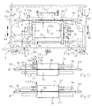
- the designated in its entirety by 1 device consists of several component units such.
- B. a standing on the ground frame (not shown), in which a extending in the longitudinal direction free passage 2 is arranged for the strand 3.
- at least one cutting device 4 is provided with a transverse to the passage 2 extending cutting wire 4a, wherein the strand 3 before cutting on one or more desired sides preferably in a common transverse plane arranged notches 5a is provided, which extend transversely, and in which the plastic material of the strand 3 is cut transversely. Due to the cutting in the notches 5a, a degree of cutting protruding beyond the outer surfaces of the strand sections 3a is avoided in each case.
- the device 1 is also functional and advantageous without the notch function.
- notching the strand 3 penetrating notching strips 5b, 5c, 5d, 5e are provided in its plastic material, which will be described below.
- notching a Kerbdruck is exercised against the strand 3. It is therefore advantageous to arrange at least two notching strips 5b, 5c on opposite sides of the strand 3, so that the notch pressure is canceled when the notches are simultaneously cut.
- notching strips 5b, 5c, 5d are provided on three sides on the right and left side and on the upper side of the strand 3.
- Other notched bar arrangements e.g. B. all-side notching strips 5b, 5c, 5d, 5e are possible.
- One or more in the longitudinal direction of the passage 2 successively arranged notching devices 5 are each arranged and supported on a support module 9, the z. B. in the sense of a surrounding the passage 2 support frame 9a is formed with a laterally superior lower cross member 24, whose height is a multiple of its horizontal thickness and z, for example, has the shape of a vertically arranged bar.
- the cutting device 4 is not shown for reasons of simplification, which in the context of the invention on the support frame 9a (not shown) or on a supporting frame 9a carrying slider S ( Fig. 11 ) is arranged and worn on it.
- a strand 3 For conveying the strand 3 through the device 1 in the passage 2 serves a strand 3 preferably continuously advancing conveyor 1a (in Fig. 3 indicated), with several in the passage direction 2a successively arranged conveyor sections, z. B. depending on a conveyor belt and sliding sections can be formed.
- the strand 3 can pass from an extruder to the conveyor 1 a.
- the known per se and in Fig. 11 shown slider S, which carries one or more successively arranged carrier modules 9 with a notching device 5 and the one or more cutting devices 4, along the passage direction 2a back and forth and is moved during notching and cutting at the Vorzis ancient of the strand 3 before and then is moved back to its original position, from which a next notching and cutting process takes place.
- the cutting wire 4a for cutting can always be moved from one side of the passage to the other side and after an adjustment (spreading of the kerf 4b) of the cut Longitudinal section 3a are moved back in an idle stroke, which is referred to as unilateral or monodirectional cutting (known per se).
- unilateral or monodirectional cutting known per se
- the slider S is by a longitudinal guide S1 on the frame or attachments of the device 1, z. B. on both sides longitudinally extending guide rods 8, mounted and movable by a longitudinal drive S2 with the conveying speed forward and back again.
- the notching device 5 is arranged and supported on a support module 9 in the form of a support frame 9a, which extends transversely to the passage 2 from one side to the other side and is preferably designed as a frame.
- the support module 9 or the support frame 9a may be plate-shaped or made of profiles, for. As U-profiles or pipes square cross-section, be composed and arranged edgewise.
- the support module 9 is formed by a frame 9a, each defining two horizontal and vertical frame sections 9b, 9c, 9d, 9e a square through hole 11.
- the passage 2 is located in the through hole 11, the latter being dimensioned larger in cross section than the passage 2, so that between the inner edge of the frame portions 9b 9c, 9d, 9e and the passage 2 two opposing side notching strips 5b, 5c an upper notch strip 5d and an optional lower notch bar 5e have space.
- the notching strips 5b to 5d or 5e are movable transversely to the center axis 2b of the passage 2 between a notch starting position releasing the free passage 2 for the strand 3 and a notch position encompassing the strand 3 around the depth of the notch 5a.
- the upper and side frame portions 9b, 9c, 9d are in the embodiments according to Fig. 1 to 7 and 11 by hollow profiles, z. B. U-profiles arranged parallel to the central axis 2a of the passage 2 and extending in the circumferential direction web walls 9f and, in particular with outwardly projecting U-legs 9g formed.
- the transversely to the passage 2 extending length of the notched strips 5b to 5e are adapted to the transverse dimensions of the strand 3, that they press in their notch positions in the circumferential direction continuous or here a three-sided notch 5a in the strand 3.
- the upper notching strip 5d (or also the lower notching strip 5e) is formed so long that its end regions overlap the two lateral notching strips 5b, 5c at least in their notched position.
- notched strips 5b to 5d or 5e with the cross-sectional shape of a symmetrical with respect to the vertical wedge whose wedge angle z. B. is about 90 ° (not shown).
- z. B. located in a common transverse plane notching strips 5b to 5d and 5e with respect to the cutting plane E and the cutting device 4 in the passage direction offset by the length of a strand longitudinal section 3a.
- FIG. 2 and the following show- the notching device 5 and the associated cutting device 4 in a common vertical transverse or sectional plane E, wherein the notching device 5 is formed by a known chamfering device 14, which at the edges of the front ends of the still to be cut longitudinal sections 3a and Moldings chamfer 14a push into the strand 3, wherein each two adjacent to the cutting plane E chamfers 14a form a common notch 5a.
- two respective notched strips 4, namely so-called chamfering strips 15, are arranged parallel to one another on the respective sides of the conveying passage 2, which - viewed transversely to the passage 2 - correspond to the embodiment of undivided notching strips.
- the notches and the cutting can be carried out at about the same time or in succession, the chamfering strips 15 not only providing the cutting wire 4a with a guide, but also avoiding warping of the strand material or cutting burrs.
- the chamfer surfaces 15c corresponding to the desired cross-sectional shape of the chamfers 14a on the chamfering strips 15 are preferably also wedge surfaces which, with the transverse sectional plane E, enclose an acute angle W1 of, in particular, approximately 45 ° so that the common notch angle is approximately 90 °.
- the respectively formed notched strips 5b to 5d and 5e form on each associated side of the passage 2 a moving unit and are each in a transverse guide 17 by a notch drive 18 transversely between the notch initial position and the Notch position movable back and forth.
- the transverse guide 17 may be formed by one or two guide rods 17a spaced apart from one another, which are displaceably mounted in corresponding guide holes in the associated carrier module 9 or in the associated web wall 9f.
- the notch drive 18 may, for. B. be formed by a cylinder piston drive, the cylinder is supported on the support module 9 and attack the piston rod on the base member 16 and form the guide rods 17a.
- the notch drives 18 are arranged in the cavities of the hollow sections, here between the U-legs 9g of the U-shaped frame sections 9b, 9c, 9d, for compact and small and stable construction and connected to the associated web wall 9f, e.g. screwed, wherein they rest against the outside of the web walls 9f.
- the frame portions 9b, 9c, 9d may be mitred and interconnected, e.g. by welding.
- the notching strips 5b to 5d or 5e or their drives 18 attacks A are assigned to the notch movement of the notching strips in the notch position and z. B. limit even in the starting position.
- the stops A are preferably adjustable, so that the depth of the notches 5a is variable and adjustable. In the embodiments according to Fig. 1 to 6 the stops A of the respect.
- the stops A can be formed by lockable screws 19a, which engage a stop carrier strip 19 and are adjustable and lockable. At the respective notch movement find the stop screws 19a on the frame 9a or attachments thereof their desired stop.
- the stop carrier strips 19 may, for. B. arranged on the outer sides of the notch drives 18 and attached to double or continuous piston rods.
- the two overlapped notching strips 5b, 5c or chamfering strips 15 can be adapted with their end faces 15d to the contour or bevel of the notched surface 15c of the adjacent overlapping Anfasological 15, wherein the overlapped Anfasangn 15 at their overlapping Anfasangn 15 facing end faces, z. B. are formed obliquely and abut the Anfas vom 15c in the notch position.
- circumferential chamfers 14a are notched, and the Anfasangn 15 stabilized by a mutual investment and support.
- At least two support frame 9a which also have at least the distance a from each other for the cutting wire 4a and wear in the region of their sides facing each other the Anfasangn 15 on the respective peripheral sides.
- the Anfasologicaln 15 associated with the beginning and end modules Ma, Me namely the front chamfer strips 15 of the first chamfer strip arrangement and the rear chamfer strips 15 of the last chamfer strip arrangement are attached on one side to the associated base part 16 (see FIG Fig. 5 and 6 ).
- plate-shaped support member 20 for the cut longitudinal portion 3a In front of the cutting plane E or between the cutting planes E1, E2. plate-shaped support member 20 for the cut longitudinal portion 3a, whose top is located at the level of the top of the existing conveyor 1a for the strand 3, and which is supported at the lower portion of the associated support frame 9a.
- the cutting devices 4 each have two cutting wire holders 21, which are guided vertically and displaceably by a holder guide 22 transversely to the passage 2, in the present embodiment and are reciprocable therein by a cutting drive 4d, in particular both wire holders 21 are simultaneously and uniformly displaceable ,
- the two holder guides 22 are each formed by a preferably rotatably secured rod guide, for example with one or two longitudinally arranged guide rods 22a on both sides, which extend on the outside of the associated support members 20 vertically, and are fastened with their lower ends to a crossbeam 23a , and are connected and stabilized at their upper ends by a cross bar 23b attached thereto.
- the wire holder 21 may be formed with a guide piece 21a and a holder piece 21b with an only indicated fastening device for the associated cutting wire 4a one or two parts.
- FIGS. 11 and 12 in the longitudinal direction of the passage 2 adjacent to each other and by a slot 20a and the distance f spaced from each other support members 20 each be assembled by means of their supporting cross members 24 to a support frame slide unit.
- the cross member 24 may each be supported by an associated cross member foot or by a longitudinally extending foot wall 24a on both sides on the example plate-shaped slide S and secured by a numbered in its entirety with 56 fastening device.
- the slot 20a or distance f is larger by a preferably mutual movement play than the cross-sectional dimension d of the cutting wire 4a or the distance a between the Anfasang 15th
- an adjusting device 26 which is effective between the support member 20 and the associated cross member 24 and the associated support member 20 with the longitudinal section 3a thereon after opening the notching devices 5 on such Width of the expansion joint 4c spreads that the associated cutting wire 4a can be moved back without a clamping with the spread longitudinal section 3a through the Sp Schwarzfuge 4c and the slot 20a, in particular with lateral play to at least one cut surface, preferably to both opposite cut surfaces.
- the cutting devices 4 are assigned notching devices 5, these together with the associated supporting parts 20 each form an adjusting movement unit and preferably also part assembly B1, so that the associated notching device 5 is also adjusted when the respective carrying part 20 is adjusted.
- the carrier modules 9 or support frame 9a carrying the notching devices 5 are fastened, for example screwed, by a preferably releasable fastening device 30, in each case on the associated support strips 20b.
- the notching devices 5 with the chamfering strips 15 arranged above the rear and front edges of the supporting parts 20 are thus likewise adjusted by the adjusting devices 26. If no adjusting device 26 and therefore no Support strips 20b are present, as in the embodiments according to Fig. 21 and 26 may be in the central longitudinal region, the associated support frame 9a on the cross member 24 can be fastened.
- Such adjusting device 26 is first based on the Fig. 8 to 10 explained.
- the adjusting device 26 has an adjustment guide 26a and an adjusting drive 26b, which are respectively effective between the associated support member 20 and the cross member 24 carrying it.
- the guide length and the adjustment stroke L2 are each so large that the desired width of the expansion joint 4c is achieved.
- the adjustment drive 26b can be effective in both opposite adjustment directions or only in the respective desired adjustment or spreading direction 28. In the latter case, the return movement of the support member 20 z. B. by a return spring 27 with a sufficient return force, which can be generated or increased by the spreading or adjusting movement and a further tensioning of the spring 27.
- the movement drive 26b may be formed by a in the adjusting device 28 or back and thus single or double effective piston cylinder drive, the z. B. is pneumatically or hydraulically effective or be formed by a plunger, which is electrically movable in the adjustment direction 28 or back.
- the or the support members 20 are each supported by two transversely extending and upright support strips 20b, which on both sides of the associated cross member 24, z. B. underside, are arranged on the support member 20 and have such a large and longitudinal distance from each other that the cross member 24 and thus the support member 20 can perform a sufficiently large stroke L2.
- a movement guide 26a and a movement drive 26b are provided on both sides of the central axis 2b in order to avoid jamming during movement.
- each movement guide 26a may be formed by a guide pin 26c, which passes through a guide hole 26d in the cross member 24 with play and is fastened with its ends to the support strips 20b.
- the movement drives 26b may be arranged, for. B. in lateral recesses 26 e, to realize a small or narrow construction.
- the return spring 27 may be arranged in a recess 26 f, which is preferably formed in the cross member 24.
- a stop 29 which is preferably arranged in alignment with the movement drive 26b and z.
- B. between the cross member 24 and one of the support strips 20 b may be arranged, preferably as a stopper piece in a recess 26 g, to reduce the design size.
- the Fig. 9 shows the adjusting device 26 for the associated support member 20 in its rear starting and cutting position, in which it has the rear adjacent support member 20 (indicated) has a slot 20 a forming distance f, which is greater than the cross-sectional dimension or the diameter d of Cutting element or cutting wire 4a.
- Fig. 12 and 14 show two adjacent support members 20 with a longitudinal section 3a thereon at or right after the cut and unspread, so that between the cut surfaces, the kerf 4b is present.
- a further improvement can be achieved by an arrow L3v directed forward displacement of the cutting wire 4a, as it FIGS. 14, 15 and 18 demonstrate.
- the cutting device 4 and the wire holders 21 are associated with a wire adjustment device 31, which makes it possible to displace the cutting wire section located at right angles to the movement length L3 in the transverse region of the longitudinal sections 3a, in the embodiment according to FIG Fig. 15 . 16 and 17 to move forward (L3v), and thereby to be spaced from the sectional surface of the strand 3 or a rear longitudinal section 3a, so that the cutting wire 4a can be moved back laterally without touching the cut surface of the strand 3 or damage.
- two adjusting devices 31 are respectively provided, preferably in the region of the wire holders 21, which can be of the same design, so that the description requires only one adjusting device 31.
- This can, for. Example, be formed by a thrust member 31 a, which can be arranged and held at one of the wire holder 21 in addition to the cutting wire 4a inwardly projecting support arm 21 a.
- the thrust member 31a is slidable by a linear actuator 31b against the cutting wire 4a and beyond its normal position.
- the thrust drive 31b may be an electric, pneumatic or hydraulic drive, wherein the thrust member 31a may be formed by the cylinder or the piston of a piston cylinder. It is also advantageous in this embodiment, the thrust member 31a in a recess 31c in the thrust member 31a supporting support arm 21a sunk to order to achieve a small construction width.
- the device 1 or cutting device 4 so space, especially short, to design that even relatively small lengths L1 of the longitudinal sections 3a can be realized, for small or short longitudinal sections 3a, z.
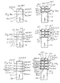
- FIG. 12 to 15 show the adjustment device 26 for longitudinal or forward adjustment of a first cutting plane E1 or kerf 4b adjacent or upstream support member 20 with the longitudinal portion 3a thereon.
- the respectively opposite or behind this first cutting plane E1 located support member 20 requires no adjustment, since it is located under the front end of the strand 3. Therefore, these support members 20 are in Fig. 12 to 15 also drawn without support member adjustment device 26.
- the device 1 according to the invention is also suitable for cutting the strand 3 with several, z. B. two to five and even more pieces, arranged in the longitudinal direction one behind the other notching devices 5 and cutting devices 4 and cutting wires 4a, as the Fig. 6, 7 . 16 and the following show.
- the device 1 thus has only a notching device 5 and a cutting device 4, the practice has shown that the cutting wire 4 a can be moved back without spreading the kerf 4 b provided that the respective sectional surfaces of the longitudinal sections 3 a no particularly high demands on one clean cut surface can be made. This will be on it attributed to the fact that the only cut longitudinal section is sufficiently movable and can yield slightly under an axial clamping effect. In contrast, the clamping action of the cutting wire 4a during its return movement through the kerf 4b is greater when several longitudinal sections 3a are cut one behind the other with a plurality of cutting devices 4.
- the first embodiment variant is formed in each case by the forward and back adjustable support member adjustment device 26, which allows the respectively associated support member 20 with the associated longitudinal portion 3a by a movement clearance for the cutting wire 4a in the kerf 4b so far along - here after front - to move that there is at least one-sided movement play between the cutting wire 4a and the longitudinal portion 3a it is upstream, as it Fig. 13 shows.
- the length L3v may be so large that the cutting wire 4a sweeps along the back sectional surface of the upstream longitudinal portion 3a or the front sectional surface of the downstream longitudinal portion 3a (not shown).
- Fig. 14 shows such a combined embodiment before spreading the kerf 4b z. B. during cutting.
- the cutting devices 4 in which the adjustment of the respective cutting wire 4a is independent of the adjustment of the associated support member 20, it requires a separate wire adjustment device to the associated Cutting wire 4a in each case by the adjustment length L2 of the associated, her upstream, support member 20 and the sum of the adjustment lengths L2 of this support member 20 in the adjustment direction 28 downstream support members 20 to adjust.
- the cutting wire is preferably adjusted in each case in addition to the above-described movement play of the cutting wire 4 a in the kerf 4 c in order to obtain a movement on both sides of the cut surfaces. For a spread or adjustment of at least one support part 20 and of the cutting wire 4 a to be described later, the above applies correspondingly to the opposite adjustment direction 28.
- the adjustment length L2v, L2h, L3v, L3h directed towards the rear or the rear is thus increasing due to the resulting addition of the adjustment lengths L2v or L2h and L3v or L3h.
- the cutting wire 4a downstream support member 20 is formed without an adjusting device 26.
- more free space in the longitudinal direction is available, so that the associated cross member 24 can be formed with a larger thickness d2, than the thickness d1 of the cross member 26 with an adjusting device 31st
- the device 1 has a plurality of cutting devices 4, eg with associated notching devices 5, lying one behind the other, eg. B. three notching devices and two cutting devices 5, 4 according to Fig. 6 . 16a and 17a or four notching devices and three cutting devices 5, 4 according to Fig. 7 . 16b and 17b or five notching devices and four cutting devices 5, 4 according to Fig. 16c and 17c , then it is necessary for the or the first or second or further cutting devices 4.1, 4.2, 4.3, 4.4 upstream support members 20.1, 20.2, 20.3, 20.4 of an embodiment according to Fig. 18 , in which two or the support parts arranged one behind the other, 20.1 to 20.4 according to Fig.
- a support member adjustment device 26 and the associated cutting devices are each assigned a wire adjustment device 31 to adjust the respectively associated support member and the respective associated cutting wire 4a by the required movement length L2v, L3v.
- the respective adjustment length L2v, L3v in the direction forward from support member 20 to support member 20 is increased in order to obtain the respectively required movement play.
- the maximum adjustment length L2v is determined by the width of the associated transverse slot 20a, taking into account that in a maximum adjustment length L2v of the cutting wire 4a should still have a play of movement to him upstream edge of the associated transverse slot.
- the respective adjustment length L2v or L3v is therefore equal to or greater than the sum of the previous adjustment lengths L2v, L3v.
- FIGS. 12 to 18 show the aforementioned third embodiment variant, with the two above-described embodiment variants according to FIGS. 12 to 18 can be combined in so far as at least one support member adjustment device 26 and at least one wire adjustment device 31 in a reverse arrangement can be combined.
- Fig. 19a to 20c are two cutting devices 4 and three notching devices 5 ( FIGS. 19a and 20a ) to four cutting devices 4 and five notching devices 5 (FIG. Fig. 19c and 20c ) intended.
- Fig. 19a to 25th is to enable special adjustment or spreading movements of all or certain support members 20, an adjusting device 35 is provided, with all supporting parts 20.1 to 20.4 or 20.5 with the strand longitudinal sections thereon 3a by the length L4 together forward and later back again , And to generate a distance i between the rearmost longitudinal portion 3al and the strand 3.
- the adjustment with the adjusting devices 26, 31 then takes place to the rear ( Fig. 19a to 20c ) or forward and backward ( FIGS. 21 and 22 ).
- the distance i is equal to or greater than the sum of the rearward adjustment lengths L2h and L3h of the associated support parts 20 and cutting devices 4, which by the respectively associated adjusting device 26 or 31 to the front (L2v, L3v) and / or to the rear (L2h, L3h) are adjustable.
- This configuration makes it possible, in the central region of the cut longitudinal sections 3a one or two successively arranged support members, for. B. 20.2, 20.3, adjustable in to leave their mounted position or without an adjusting device 26 and to arrange behind and in front of these supporting parts 20.2, 20.3 arranged supporting parts 20.1, 20.4 and 20.5 respectively with the associated adjusting device 26 to the rear or to the front.
- the wire adjusting devices 31 also applies accordingly to the wire adjusting devices 31.
- the wire adjusting devices 31.2 and 31.4 or not be provided to move the respective cutting wires 4a2, 4a4 in the central region of the expansion joints 4c or not.
- a wire adjusting device 31.1 and 31.5 can be present and each designed so that with them the cutting wires 4a1, 4a5 are adjustable so that they are located on the associated cutting wall of the kerf 4b1 or 4b5 or in between.
- FIGS. 21 and 22 demonstrate.
- the adjusting device 37 may have a longitudinally for the 3av and possibly for the front support member 20.5 common and thus correspondingly long trained plate-shaped support member 20.6 that slidably mounted in a longitudinal guide 38 on the carriage S and by an indicated longitudinal drive 39 to the movement length L5 forward and later moving backward, which is equal to or greater than the sum of the forward displacement lengths L2v and L3v.
- the longitudinal guide 38 on both sides of the conveyor passage 2 between the support member 20.5 and the carriage S. be arranged.
- the longitudinal guide 38 can each be formed by a longitudinally extending and two bearing blocks 41 arranged one behind the other in bearing holes 41a and longitudinally projecting guide rods 42.
- the bearing blocks 41 are arranged on the slider S, and the guide rods 42 are fixed to the end of the support member 20.5 downwardly projecting webs 43.
- the support frame slide unit is also advanced at the speed of pre-promotion, the notching devices 5 and the cutting devices 4 are operated, and wherein the notches 5 a pressed into the strand 3 and then the cuts preferably simultaneously by moving the Cutting wires 4a are performed from one side of the strand 3 to the other side.
- the width b of preferably equal width transverse slots 20a should be as small as possible in view of a sufficient surface pressure on the support members 20.
- the width b of the transverse slots 20a in the unspread starting position corresponds to the sum of the cross-sectional dimension of the cutting element or wire 4a, e.g. about 1 mm, and a two-sided movement of e.g. about 1 mm, that is about 3 mm.
- a cutting wire 4a can then be moved back relatively harmlessly through an unspread kerf 4b, when adjacent kerfs 4b are spread apart to form expansion joints 4c.
- the cut longitudinal portions 3a are spread apart to the return of the cutting wires 4a to the other side to resist or no resistance to the other and at least one of the two cut surfaces to protect and not to affect.
- the first kerf 4b1 (FIG. Fig. 17a to 17c ) need not be spread for the aforementioned reasons, when the second kerf 4b2 and the following in the adjustment direction kerfs 4b3, 4b4 are spread.
- the cutting wires 4a1 or 4a2 disposed downstream of the first and second support members 20.1 or 20.2 are advanced (L3v) by a sufficient amount of movement between the cut surfaces, e.g. about 2 mm.
- the respective other upstream cutting wires are respectively adjusted by one of the sum of the downstream supporting parts plus the associated movement clearance (L3v) in each case to the front.
- Fig. 16a to 17c can for the the kerf 4b1 in the first section plane E1 upstream adjustment 26 according to an embodiment FIGS. 12 and 13 or according to FIGS. 14 and 15 be used.
- the other further upstream kerfs 4b2 and following may be an embodiment according to Fig. 18 be used.
- the cutting wires 4a1, 4a2 arranged downstream of the first or second support part 20.1, 20.2 are advanced (L3v) by a sufficient movement play between the cut surfaces, e.g. about 2 mm.
- the respective other upstream cutting wires are each adjusted by one of the sum of the downstream in the adjustment direction 28 supporting parts, preferably plus the associated movement clearance L3v, respectively to the front.
- the cut longitudinal portions 3a are simultaneously moved forward by a movement length L4 equal to or greater than the sum of the rearward spread movement lengths L2h, L3h, the adjustment movements being performed in the rearward direction or according to FIG FIGS. 21 and 22 partly to the front and to the back.
- the embodiments according to Fig. 19a to 25th thus differ from the embodiments according to Fig. 16a to 17c inter alia in that initially the cut longitudinal sections 3a or associated support parts are moved forward together and then in the above-described sense to the rear (FIG. Fig. 19a to 20c ) or backwards and forwards ( FIGS. 21 and 22 ) are spread, wherein the common Verstell strict L4 is available for rearward spreading of the respective kerfs available.
- the foremost of the kerfs ( Fig. 19a to 20c ) or a kerf in the middle region ( FIGS. 21 and 22 ) remain unspread or optionally spread.
- the foremost support part 20.5 is a part of the further adjustment device 37 for adjusting the longitudinal sections 3av (and 3a5) upstream of the cut longitudinal sections 3a, as has already been described.
- the longitudinal sections 3av are thus also advanced, wherein the additional longitudinal direction 3av and the foremost cut longitudinal section 3a5 are advanced by an additional actuation of the adjusting device 37, so that the subsequent forward spread of the supporting part is achieved 20.4 does not stand in the way.
- the movement of the adjusting device 37 forward takes place at the same time or before an adjustment forward of the frontmost support member 20.4 or 20.5.
- FIGS. 21 and 22 can thus be used in the area of the unspread kerf 4b two stationary support members 20.2, 20.3, whereby the construction and function is much easier.
- the cutting wires 4 a are to be moved transversely to the extent that they are located next to the strand 3 during cutting.
- the cutting wires 4a may be located in the transverse direction between the respectively adjacent support members 20 or they may also continue on be moved so that they are outside the support members 20, z. B. above and below or laterally outside.
- the adjustment movement of the cutting wires 4a is dependent on the adjustment movement of the associated support members 20, so that they should be adjusted approximately simultaneously for adjustment or spreading.
- their adjusting movement is independent, so that they can be adjusted before, at the same time or after the adjusting movement of the supporting parts 20.
- the device 1 according to Fig. 26 which largely conforms to the design Fig. 7 . 11 and 21 corresponds to two major differences.
- the support frames 9a are not made of hollow profiles but of solid profiles quadrangular, in particular rectangular, cross-section and light material such as light metal, for example aluminum.
- the longer cross-sectional dimension of the cross sections of the frame portions 9b, 9c, 9d and 9e, respectively, is directed in the longitudinal direction of the device 1 and the passage 2, respectively.
- the frame portions 9b, 9c, 9d and 9e are in the corner regions of the U-shape dull set together, wherein the one, in particular upper frame part 9c, the end face of the other frame part 9b, 9d preferably overlaps both ends, and the frame parts secured in this position to each other are, for example by screws or welding.
- the frame parts 9b, 9c, 9d and 9e have at the points where there are notch drives 18, on the outside open recesses 51, the depth is limited in each case by a web wall 9f, which is located at the inner edge of the respective frame part.
- the cross-sectional size of the recesses 51 is adapted to the cross-sectional size of the notch drives so that they are inserted therein from the outside and connectable to the web wall 9f, for example, are screwed.
- the recesses 51, 51a may be prepared by a machining work, such as milling.
- Fig. 26 clearly recognizable that in the presence of a plurality of successively arranged notching devices 5, this with the respective associated and preferably adjustable support members 20 form a unit B 1, which is vorfertigbar and rationally assembled or disassembled or is interchangeable with at least one other different unit B 1 ,
- units B 1 may differ, for example, by different dimensions L1 and / or a and b and / or cross-sectional sizes for the strand 3.
- Another structural unit B2 is formed by the or all supporting parts 20 with or without adjusting device 26 with or without notching device (s) 5 or carrier module (s) 9, the foot parts 24a and the associated parts of the connecting device 56.
- This unit B2 is prefabricated mountable or removable or interchangeable with a different unit B2.
- releasable fastening or connecting device 56 is preferably formed by a quick-release connection, in particular in the form of a plug-in connection, so that a quick assembly and disassembly is possible.
- At least three, preferably four connecting devices 56 are provided, which are arranged distributed on the underside of the unit B2 and on the slider S, e.g. in the corner areas of the unit B and the slide S.
- connecting devices 56 are each formed the same and formed by a plug recess 56a and an undercut 56b and a plug-in pin 56c insertable therein, which result in a detachable plug connection.
- the plug-in recess 56a preferably extends vertically, wherein the undercut 56b adjoins the plug-in recess 56a in an angle-shaped manner in the longitudinal direction of the device 1.
- an unillustrated positively locking securing element is provided, which ensures the assembly B2 in the connecting position.
- This may be a securing plug-in pin, which, for example, a foot wall 24a and the slider S in a plug-through-hole and against an unwanted solution, against falling out, is secured.
- the undercut 56b is directed in each case to the rear, so that by inserting and advancing the assembly B2 this is movable into its connecting position.
- a release of the assembly B2 takes place in the reverse order of movement, namely first a longitudinal displacement in a release position and then by lifting the unit B2.
- the spigots 56c are laterally spaced from web portions 56d, e.g. from the slider S upwards.
- laterally effective limiting members 61 may be provided, which act as lateral stops and, for. may be formed by the web portions 56d, whose transverse distance is adapted to the corresponding transverse dimension X of the assembly B2.
- the plug-in pins 56c are arranged on upper-side mounting lugs 57 of the slider S, and the plug-in recess 56a and the undercut 56b are formed in the footwalls 24a, the plug-in recess 56a being open on the underside. This is for simplicity's sake only in Fig. 27 indicated.
- the foot walls 24a on the upper side open recesses 58 which are limited in the longitudinal direction of the device 1 by vertical fastening webs 59. These webs 59 are located in the transverse planes of the cross member 24, and they are attached to the front ends of the cross member 24, for example screwed.
- the recesses form 58 free spaces that facilitate the assembly and disassembly and the arrangement of functional parts such as hoses, and also the cutting elements 4a can dive in the lower position of movement, as it Fig. 27 exemplifies.
- Fig. 27 shows as an embodiment of a unit B2 with, for example, three, successively arranged cutting devices 4, wherein no notching devices are provided and therefore the associated device 1, the longitudinal sections 3a cuts without notches, so that the edges of the cut surfaces are sharp-edged.
- This type of cutting is suitable for such longitudinal sections 3a or blanks which may have sharp-edged cut surface edges optionally with a burr.
- the device 1 in the embodiments according to Fig. 26 and 27 be designed as described above.
Landscapes
- Engineering & Computer Science (AREA)
- Mechanical Engineering (AREA)
- Structural Engineering (AREA)
- Chemical & Material Sciences (AREA)
- Ceramic Engineering (AREA)
- Life Sciences & Earth Sciences (AREA)
- Forests & Forestry (AREA)
- Devices For Post-Treatments, Processing, Supply, Discharge, And Other Processes (AREA)
- Processing And Handling Of Plastics And Other Materials For Molding In General (AREA)
Applications Claiming Priority (1)
| Application Number | Priority Date | Filing Date | Title |
|---|---|---|---|
| DE200810055887 DE102008055887A1 (de) | 2008-11-05 | 2008-11-05 | Vorrichtung zum Schneiden eines Stranges aus plastischem Material, mit wenigstens einer Verstellvorrichtung zum Verstellen wenigstens eines Tragteils für einen abgeschnittenen Strang-Längsabschnitt |
Publications (3)
| Publication Number | Publication Date |
|---|---|
| EP2184147A2 true EP2184147A2 (fr) | 2010-05-12 |
| EP2184147A3 EP2184147A3 (fr) | 2011-11-30 |
| EP2184147B1 EP2184147B1 (fr) | 2013-06-12 |
Family
ID=41698180
Family Applications (1)
| Application Number | Title | Priority Date | Filing Date |
|---|---|---|---|
| EP20090174631 Not-in-force EP2184147B1 (fr) | 2008-11-05 | 2009-10-30 | Dispositif destiné à couper un boudin de matériau plastique, doté d'au moins un dispositif de réglage pour déplacer au moins un élément de support pour une section longitudinale de boudin sectionnée |
Country Status (2)
| Country | Link |
|---|---|
| EP (1) | EP2184147B1 (fr) |
| DE (1) | DE102008055887A1 (fr) |
Citations (2)
| Publication number | Priority date | Publication date | Assignee | Title |
|---|---|---|---|---|
| DE10257192A1 (de) | 2002-12-06 | 2004-06-24 | Hans Lingl Anlagenbau Und Verfahrenstechnik Gmbh & Co Kg | Drahtauslenkung an Universalabschneidern |
| DE102005021038A1 (de) | 2005-05-06 | 2006-11-23 | Hans Lingl Anlagenbau Und Verfahrenstechnik Gmbh & Co. Kg | Vorrichtung zum Trennen eines plastischen Tonstranges, mit einer allseitig wirksamen Kerbvorrichtung |
Family Cites Families (2)
| Publication number | Priority date | Publication date | Assignee | Title |
|---|---|---|---|---|
| CH182650A (de) * | 1934-10-06 | 1936-02-29 | Frey Ernst | Selbsttätige Vorrichtung zum Schneiden des von einer Tonstrangpresse gelieferten Tonstranges. |
| DE102007017485B4 (de) * | 2007-04-13 | 2014-09-04 | Hans Lingl Anlagenbau Und Verfahrenstechnik Gmbh & Co. Kg | Vorrichtung zum Trennen eines Stranges aus plastischem Material mit einem eine Kerbvorrichtung und eine Schneidevorrichtung tragenden Träger |
-
2008
- 2008-11-05 DE DE200810055887 patent/DE102008055887A1/de not_active Withdrawn
-
2009
- 2009-10-30 EP EP20090174631 patent/EP2184147B1/fr not_active Not-in-force
Patent Citations (2)
| Publication number | Priority date | Publication date | Assignee | Title |
|---|---|---|---|---|
| DE10257192A1 (de) | 2002-12-06 | 2004-06-24 | Hans Lingl Anlagenbau Und Verfahrenstechnik Gmbh & Co Kg | Drahtauslenkung an Universalabschneidern |
| DE102005021038A1 (de) | 2005-05-06 | 2006-11-23 | Hans Lingl Anlagenbau Und Verfahrenstechnik Gmbh & Co. Kg | Vorrichtung zum Trennen eines plastischen Tonstranges, mit einer allseitig wirksamen Kerbvorrichtung |
Also Published As
| Publication number | Publication date |
|---|---|
| DE102008055887A1 (de) | 2010-05-06 |
| EP2184147A3 (fr) | 2011-11-30 |
| EP2184147B1 (fr) | 2013-06-12 |
Similar Documents
| Publication | Publication Date | Title |
|---|---|---|
| EP2134519B1 (fr) | Dispositif de séparation d'un assemblage de tiges en matière plastique à l'aide d'un dispositif à entaille et d'un support portant un dispositif de découpe | |
| EP2340147B1 (fr) | Machine d'usinage pour usinage de six faces | |
| DE1957350B2 (de) | Aufteilsaegemaschine, insbesondere buntaufteilsaegemaschine | |
| DE202009008404U1 (de) | Sägemodul für die Bearbeitung von Fenster- und Fassadenprofilen | |
| DE4403228C1 (de) | Verfahren und Vorrichtung zum reihenweisen Auseinanderrücken von quaderförmigen, plastischen Porenbetonkörpern | |
| DE102005063327B4 (de) | Vorrichtung zum Trennen eines plastischen Tonstranges, mit einer allseitig wirksamen Kerbvorrichtung | |
| DE102005021038B4 (de) | Vorrichtung zum Trennen eines plastischen Tonstranges, mit einer allseitig wirksamen Kerbvorrichtung | |
| DE102011101811B4 (de) | Profilschneideinrichtung | |
| EP2184147B1 (fr) | Dispositif destiné à couper un boudin de matériau plastique, doté d'au moins un dispositif de réglage pour déplacer au moins un élément de support pour une section longitudinale de boudin sectionnée | |
| DE2312376A1 (de) | Aufteilsaegemaschine, insbesondere buntaufteilsaegemaschine | |
| EP2184146A2 (fr) | Dispositif et procédé d'écartement de fentes transversales d'un dispositif pour couper un boudin en matériau plastique | |
| EP2200789A2 (fr) | Dispositif de séparation d'un boyau de matière plastique qui peut se déplacer le long d'un passage d'acheminement, comprenant au moins un module de support portant des barres d'entaillage et des éléments de retenue de fil de coupe | |
| EP2022613A2 (fr) | Dispositif de poussée dans une installation de coupe de béton poreux | |
| EP2207652B1 (fr) | Dispositif de séparation d'un boyau de matière plastique qui peut se déplacer le long d'un passage d'acheminement, comprenant un entraînement d'entaillage | |
| DE68903042T2 (de) | Strangpressvorrichtung mit rotierender walze. | |
| DE2428115B2 (de) | Vorrichtung zum schneiden eines noch plastischen porenbetonblockes | |
| EP1764200B1 (fr) | Appareil pour couper un boudin extrudé en matériau déformable plastiquement, en particulier en argile | |
| EP0452673A2 (fr) | Dispositif de fixation pour fabrication des joints d'angle à onglet pour châssis de fenêtre en bois | |
| EP1048903B1 (fr) | Raies de fixation pour tubes de chauffage par le sol ansi que procédé et appareil pour manufacturer les raies | |
| DE19956459B4 (de) | Plattenauflageleiste für Maschinentische von Plattensägemaschinen | |
| EP1764177A1 (fr) | Dispositif pour couper de barres de vitrage à longueur et procédé pour couper de barres de vitrage ou similaires | |
| DE2150542B2 (de) | Profilstahlschere mit einem geradlinig bewegten scherenschlitten | |
| DE4302119A1 (de) | Arbeitsmaschine insbesondere Abkantpresse | |
| DE102005020745A1 (de) | Verfahren zur Herstellung von Auflagesätteln, Maschine und Sattel | |
| DE10039738A1 (de) | Kreissägeanlage mit Doppel-Achse |
Legal Events
| Date | Code | Title | Description |
|---|---|---|---|
| PUAI | Public reference made under article 153(3) epc to a published international application that has entered the european phase |
Free format text: ORIGINAL CODE: 0009012 |
|
| AK | Designated contracting states |
Kind code of ref document: A2 Designated state(s): AT BE BG CH CY CZ DE DK EE ES FI FR GB GR HR HU IE IS IT LI LT LU LV MC MK MT NL NO PL PT RO SE SI SK SM TR |
|
| AX | Request for extension of the european patent |
Extension state: AL BA RS |
|
| RIC1 | Information provided on ipc code assigned before grant |
Ipc: B26D 1/553 20060101ALI20110606BHEP Ipc: B28B 11/08 20060101ALI20110606BHEP Ipc: B28B 11/16 20060101AFI20100309BHEP |
|
| PUAL | Search report despatched |
Free format text: ORIGINAL CODE: 0009013 |
|
| AK | Designated contracting states |
Kind code of ref document: A3 Designated state(s): AT BE BG CH CY CZ DE DK EE ES FI FR GB GR HR HU IE IS IT LI LT LU LV MC MK MT NL NO PL PT RO SE SI SK SM TR |
|
| AX | Request for extension of the european patent |
Extension state: AL BA RS |
|
| RIC1 | Information provided on ipc code assigned before grant |
Ipc: B28B 11/08 20060101ALI20111025BHEP Ipc: B26D 1/553 20060101ALI20111025BHEP Ipc: B28B 11/16 20060101AFI20111025BHEP |
|
| 17P | Request for examination filed |
Effective date: 20120530 |
|
| GRAP | Despatch of communication of intention to grant a patent |
Free format text: ORIGINAL CODE: EPIDOSNIGR1 |
|
| GRAS | Grant fee paid |
Free format text: ORIGINAL CODE: EPIDOSNIGR3 |
|
| GRAA | (expected) grant |
Free format text: ORIGINAL CODE: 0009210 |
|
| AK | Designated contracting states |
Kind code of ref document: B1 Designated state(s): AT BE BG CH CY CZ DE DK EE ES FI FR GB GR HR HU IE IS IT LI LT LU LV MC MK MT NL NO PL PT RO SE SI SK SM TR |
|
| REG | Reference to a national code |
Ref country code: GB Ref legal event code: FG4D Free format text: NOT ENGLISH |
|
| REG | Reference to a national code |
Ref country code: CH Ref legal event code: EP |
|
| REG | Reference to a national code |
Ref country code: AT Ref legal event code: REF Ref document number: 616506 Country of ref document: AT Kind code of ref document: T Effective date: 20130615 |
|
| REG | Reference to a national code |
Ref country code: IE Ref legal event code: FG4D Free format text: LANGUAGE OF EP DOCUMENT: GERMAN |
|
| REG | Reference to a national code |
Ref country code: DE Ref legal event code: R096 Ref document number: 502009007325 Country of ref document: DE Effective date: 20130808 |
|
| REG | Reference to a national code |
Ref country code: CH Ref legal event code: NV Representative=s name: BOHEST AG, CH |
|
| PG25 | Lapsed in a contracting state [announced via postgrant information from national office to epo] |
Ref country code: SE Free format text: LAPSE BECAUSE OF FAILURE TO SUBMIT A TRANSLATION OF THE DESCRIPTION OR TO PAY THE FEE WITHIN THE PRESCRIBED TIME-LIMIT Effective date: 20130612 Ref country code: NO Free format text: LAPSE BECAUSE OF FAILURE TO SUBMIT A TRANSLATION OF THE DESCRIPTION OR TO PAY THE FEE WITHIN THE PRESCRIBED TIME-LIMIT Effective date: 20130912 Ref country code: GR Free format text: LAPSE BECAUSE OF FAILURE TO SUBMIT A TRANSLATION OF THE DESCRIPTION OR TO PAY THE FEE WITHIN THE PRESCRIBED TIME-LIMIT Effective date: 20130913 Ref country code: ES Free format text: LAPSE BECAUSE OF FAILURE TO SUBMIT A TRANSLATION OF THE DESCRIPTION OR TO PAY THE FEE WITHIN THE PRESCRIBED TIME-LIMIT Effective date: 20130923 Ref country code: LT Free format text: LAPSE BECAUSE OF FAILURE TO SUBMIT A TRANSLATION OF THE DESCRIPTION OR TO PAY THE FEE WITHIN THE PRESCRIBED TIME-LIMIT Effective date: 20130612 Ref country code: SI Free format text: LAPSE BECAUSE OF FAILURE TO SUBMIT A TRANSLATION OF THE DESCRIPTION OR TO PAY THE FEE WITHIN THE PRESCRIBED TIME-LIMIT Effective date: 20130612 Ref country code: FI Free format text: LAPSE BECAUSE OF FAILURE TO SUBMIT A TRANSLATION OF THE DESCRIPTION OR TO PAY THE FEE WITHIN THE PRESCRIBED TIME-LIMIT Effective date: 20130612 |
|
| REG | Reference to a national code |
Ref country code: NL Ref legal event code: VDEP Effective date: 20130612 |
|
| REG | Reference to a national code |
Ref country code: LT Ref legal event code: MG4D |
|
| PG25 | Lapsed in a contracting state [announced via postgrant information from national office to epo] |
Ref country code: HR Free format text: LAPSE BECAUSE OF FAILURE TO SUBMIT A TRANSLATION OF THE DESCRIPTION OR TO PAY THE FEE WITHIN THE PRESCRIBED TIME-LIMIT Effective date: 20130612 Ref country code: BG Free format text: LAPSE BECAUSE OF FAILURE TO SUBMIT A TRANSLATION OF THE DESCRIPTION OR TO PAY THE FEE WITHIN THE PRESCRIBED TIME-LIMIT Effective date: 20130912 |
|
| PG25 | Lapsed in a contracting state [announced via postgrant information from national office to epo] |
Ref country code: LV Free format text: LAPSE BECAUSE OF FAILURE TO SUBMIT A TRANSLATION OF THE DESCRIPTION OR TO PAY THE FEE WITHIN THE PRESCRIBED TIME-LIMIT Effective date: 20130612 |
|
| PG25 | Lapsed in a contracting state [announced via postgrant information from national office to epo] |
Ref country code: SK Free format text: LAPSE BECAUSE OF FAILURE TO SUBMIT A TRANSLATION OF THE DESCRIPTION OR TO PAY THE FEE WITHIN THE PRESCRIBED TIME-LIMIT Effective date: 20130612 Ref country code: IS Free format text: LAPSE BECAUSE OF FAILURE TO SUBMIT A TRANSLATION OF THE DESCRIPTION OR TO PAY THE FEE WITHIN THE PRESCRIBED TIME-LIMIT Effective date: 20131012 Ref country code: EE Free format text: LAPSE BECAUSE OF FAILURE TO SUBMIT A TRANSLATION OF THE DESCRIPTION OR TO PAY THE FEE WITHIN THE PRESCRIBED TIME-LIMIT Effective date: 20130612 Ref country code: CZ Free format text: LAPSE BECAUSE OF FAILURE TO SUBMIT A TRANSLATION OF THE DESCRIPTION OR TO PAY THE FEE WITHIN THE PRESCRIBED TIME-LIMIT Effective date: 20130612 Ref country code: PT Free format text: LAPSE BECAUSE OF FAILURE TO SUBMIT A TRANSLATION OF THE DESCRIPTION OR TO PAY THE FEE WITHIN THE PRESCRIBED TIME-LIMIT Effective date: 20131014 |
|
| PG25 | Lapsed in a contracting state [announced via postgrant information from national office to epo] |
Ref country code: PL Free format text: LAPSE BECAUSE OF FAILURE TO SUBMIT A TRANSLATION OF THE DESCRIPTION OR TO PAY THE FEE WITHIN THE PRESCRIBED TIME-LIMIT Effective date: 20130612 Ref country code: NL Free format text: LAPSE BECAUSE OF FAILURE TO SUBMIT A TRANSLATION OF THE DESCRIPTION OR TO PAY THE FEE WITHIN THE PRESCRIBED TIME-LIMIT Effective date: 20130612 Ref country code: RO Free format text: LAPSE BECAUSE OF FAILURE TO SUBMIT A TRANSLATION OF THE DESCRIPTION OR TO PAY THE FEE WITHIN THE PRESCRIBED TIME-LIMIT Effective date: 20130612 |
|
| PLBE | No opposition filed within time limit |
Free format text: ORIGINAL CODE: 0009261 |
|
| STAA | Information on the status of an ep patent application or granted ep patent |
Free format text: STATUS: NO OPPOSITION FILED WITHIN TIME LIMIT |
|
| BERE | Be: lapsed |
Owner name: HANS LINGL ANLAGENBAU UND VERFAHRENSTECHNIK G.M.B Effective date: 20131031 |
|
| PG25 | Lapsed in a contracting state [announced via postgrant information from national office to epo] |
Ref country code: DK Free format text: LAPSE BECAUSE OF FAILURE TO SUBMIT A TRANSLATION OF THE DESCRIPTION OR TO PAY THE FEE WITHIN THE PRESCRIBED TIME-LIMIT Effective date: 20130612 |
|
| 26N | No opposition filed |
Effective date: 20140313 |
|
| PG25 | Lapsed in a contracting state [announced via postgrant information from national office to epo] |
Ref country code: MC Free format text: LAPSE BECAUSE OF FAILURE TO SUBMIT A TRANSLATION OF THE DESCRIPTION OR TO PAY THE FEE WITHIN THE PRESCRIBED TIME-LIMIT Effective date: 20130612 |
|
| GBPC | Gb: european patent ceased through non-payment of renewal fee |
Effective date: 20131030 |
|
| REG | Reference to a national code |
Ref country code: DE Ref legal event code: R097 Ref document number: 502009007325 Country of ref document: DE Effective date: 20140313 |
|
| REG | Reference to a national code |
Ref country code: IE Ref legal event code: MM4A |
|
| PG25 | Lapsed in a contracting state [announced via postgrant information from national office to epo] |
Ref country code: GB Free format text: LAPSE BECAUSE OF NON-PAYMENT OF DUE FEES Effective date: 20131030 |
|
| REG | Reference to a national code |
Ref country code: FR Ref legal event code: ST Effective date: 20140630 |
|
| PG25 | Lapsed in a contracting state [announced via postgrant information from national office to epo] |
Ref country code: FR Free format text: LAPSE BECAUSE OF NON-PAYMENT OF DUE FEES Effective date: 20131031 |
|
| PG25 | Lapsed in a contracting state [announced via postgrant information from national office to epo] |
Ref country code: BE Free format text: LAPSE BECAUSE OF NON-PAYMENT OF DUE FEES Effective date: 20131031 |
|
| PG25 | Lapsed in a contracting state [announced via postgrant information from national office to epo] |
Ref country code: IE Free format text: LAPSE BECAUSE OF NON-PAYMENT OF DUE FEES Effective date: 20131030 |
|
| PGFP | Annual fee paid to national office [announced via postgrant information from national office to epo] |
Ref country code: CH Payment date: 20141024 Year of fee payment: 6 |
|
| PGFP | Annual fee paid to national office [announced via postgrant information from national office to epo] |
Ref country code: IT Payment date: 20141029 Year of fee payment: 6 |
|
| PGFP | Annual fee paid to national office [announced via postgrant information from national office to epo] |
Ref country code: DE Payment date: 20141223 Year of fee payment: 6 |
|
| PG25 | Lapsed in a contracting state [announced via postgrant information from national office to epo] |
Ref country code: SM Free format text: LAPSE BECAUSE OF FAILURE TO SUBMIT A TRANSLATION OF THE DESCRIPTION OR TO PAY THE FEE WITHIN THE PRESCRIBED TIME-LIMIT Effective date: 20130612 |
|
| PG25 | Lapsed in a contracting state [announced via postgrant information from national office to epo] |
Ref country code: CY Free format text: LAPSE BECAUSE OF FAILURE TO SUBMIT A TRANSLATION OF THE DESCRIPTION OR TO PAY THE FEE WITHIN THE PRESCRIBED TIME-LIMIT Effective date: 20130612 Ref country code: TR Free format text: LAPSE BECAUSE OF FAILURE TO SUBMIT A TRANSLATION OF THE DESCRIPTION OR TO PAY THE FEE WITHIN THE PRESCRIBED TIME-LIMIT Effective date: 20130612 |
|
| PG25 | Lapsed in a contracting state [announced via postgrant information from national office to epo] |
Ref country code: LU Free format text: LAPSE BECAUSE OF NON-PAYMENT OF DUE FEES Effective date: 20131030 Ref country code: MK Free format text: LAPSE BECAUSE OF FAILURE TO SUBMIT A TRANSLATION OF THE DESCRIPTION OR TO PAY THE FEE WITHIN THE PRESCRIBED TIME-LIMIT Effective date: 20130612 Ref country code: HU Free format text: LAPSE BECAUSE OF FAILURE TO SUBMIT A TRANSLATION OF THE DESCRIPTION OR TO PAY THE FEE WITHIN THE PRESCRIBED TIME-LIMIT; INVALID AB INITIO Effective date: 20091030 |
|
| PG25 | Lapsed in a contracting state [announced via postgrant information from national office to epo] |
Ref country code: MT Free format text: LAPSE BECAUSE OF FAILURE TO SUBMIT A TRANSLATION OF THE DESCRIPTION OR TO PAY THE FEE WITHIN THE PRESCRIBED TIME-LIMIT Effective date: 20130612 |
|
| REG | Reference to a national code |
Ref country code: AT Ref legal event code: MM01 Ref document number: 616506 Country of ref document: AT Kind code of ref document: T Effective date: 20141030 |
|
| PG25 | Lapsed in a contracting state [announced via postgrant information from national office to epo] |
Ref country code: AT Free format text: LAPSE BECAUSE OF NON-PAYMENT OF DUE FEES Effective date: 20141030 |
|
| REG | Reference to a national code |
Ref country code: DE Ref legal event code: R119 Ref document number: 502009007325 Country of ref document: DE |
|
| REG | Reference to a national code |
Ref country code: CH Ref legal event code: PL |
|
| PG25 | Lapsed in a contracting state [announced via postgrant information from national office to epo] |
Ref country code: IT Free format text: LAPSE BECAUSE OF NON-PAYMENT OF DUE FEES Effective date: 20151030 Ref country code: LI Free format text: LAPSE BECAUSE OF NON-PAYMENT OF DUE FEES Effective date: 20151031 Ref country code: CH Free format text: LAPSE BECAUSE OF NON-PAYMENT OF DUE FEES Effective date: 20151031 Ref country code: DE Free format text: LAPSE BECAUSE OF NON-PAYMENT OF DUE FEES Effective date: 20160503 |