EP2184169A1 - Druckvorrichtung - Google Patents
Druckvorrichtung Download PDFInfo
- Publication number
- EP2184169A1 EP2184169A1 EP10154998A EP10154998A EP2184169A1 EP 2184169 A1 EP2184169 A1 EP 2184169A1 EP 10154998 A EP10154998 A EP 10154998A EP 10154998 A EP10154998 A EP 10154998A EP 2184169 A1 EP2184169 A1 EP 2184169A1
- Authority
- EP
- European Patent Office
- Prior art keywords
- ink
- receiver
- medium
- wiper member
- ink receiver
- Prior art date
- Legal status (The legal status is an assumption and is not a legal conclusion. Google has not performed a legal analysis and makes no representation as to the accuracy of the status listed.)
- Granted
Links
- 238000000034 method Methods 0.000 claims abstract description 14
- 238000004140 cleaning Methods 0.000 abstract description 10
- 239000002699 waste material Substances 0.000 description 17
- 238000012423 maintenance Methods 0.000 description 5
- 239000006096 absorbing agent Substances 0.000 description 3
- 230000008859 change Effects 0.000 description 3
- 230000004044 response Effects 0.000 description 3
- 238000007711 solidification Methods 0.000 description 3
- 230000008023 solidification Effects 0.000 description 3
- 238000010521 absorption reaction Methods 0.000 description 2
- 238000007599 discharging Methods 0.000 description 2
- 230000006872 improvement Effects 0.000 description 2
- 230000004048 modification Effects 0.000 description 2
- 238000012986 modification Methods 0.000 description 2
- 230000009471 action Effects 0.000 description 1
- 230000008901 benefit Effects 0.000 description 1
- 238000011109 contamination Methods 0.000 description 1
- 230000010485 coping Effects 0.000 description 1
- 238000001514 detection method Methods 0.000 description 1
- 230000006870 function Effects 0.000 description 1
- 230000005484 gravity Effects 0.000 description 1
- 238000009434 installation Methods 0.000 description 1
- 239000000463 material Substances 0.000 description 1
- 230000007246 mechanism Effects 0.000 description 1
- 230000009467 reduction Effects 0.000 description 1
- 230000007480 spreading Effects 0.000 description 1
- 238000003892 spreading Methods 0.000 description 1
- 238000003860 storage Methods 0.000 description 1
Images


Classifications
-
- B—PERFORMING OPERATIONS; TRANSPORTING
- B41—PRINTING; LINING MACHINES; TYPEWRITERS; STAMPS
- B41J—TYPEWRITERS; SELECTIVE PRINTING MECHANISMS, i.e. MECHANISMS PRINTING OTHERWISE THAN FROM A FORME; CORRECTION OF TYPOGRAPHICAL ERRORS
- B41J2/00—Typewriters or selective printing mechanisms characterised by the printing or marking process for which they are designed
- B41J2/005—Typewriters or selective printing mechanisms characterised by the printing or marking process for which they are designed characterised by bringing liquid or particles selectively into contact with a printing material
- B41J2/01—Ink jet
- B41J2/17—Ink jet characterised by ink handling
- B41J2/1721—Collecting waste ink; Collectors therefor
-
- B—PERFORMING OPERATIONS; TRANSPORTING
- B41—PRINTING; LINING MACHINES; TYPEWRITERS; STAMPS
- B41J—TYPEWRITERS; SELECTIVE PRINTING MECHANISMS, i.e. MECHANISMS PRINTING OTHERWISE THAN FROM A FORME; CORRECTION OF TYPOGRAPHICAL ERRORS
- B41J2/00—Typewriters or selective printing mechanisms characterised by the printing or marking process for which they are designed
- B41J2/005—Typewriters or selective printing mechanisms characterised by the printing or marking process for which they are designed characterised by bringing liquid or particles selectively into contact with a printing material
- B41J2/01—Ink jet
- B41J2/135—Nozzles
- B41J2/165—Prevention or detection of nozzle clogging, e.g. cleaning, capping or moistening for nozzles
- B41J2/16517—Cleaning of print head nozzles
- B41J2/16535—Cleaning of print head nozzles using wiping constructions
- B41J2/16541—Means to remove deposits from wipers or scrapers
-
- B—PERFORMING OPERATIONS; TRANSPORTING
- B41—PRINTING; LINING MACHINES; TYPEWRITERS; STAMPS
- B41J—TYPEWRITERS; SELECTIVE PRINTING MECHANISMS, i.e. MECHANISMS PRINTING OTHERWISE THAN FROM A FORME; CORRECTION OF TYPOGRAPHICAL ERRORS
- B41J2/00—Typewriters or selective printing mechanisms characterised by the printing or marking process for which they are designed
- B41J2/005—Typewriters or selective printing mechanisms characterised by the printing or marking process for which they are designed characterised by bringing liquid or particles selectively into contact with a printing material
- B41J2/01—Ink jet
- B41J2/17—Ink jet characterised by ink handling
- B41J2/1721—Collecting waste ink; Collectors therefor
- B41J2/1742—Open waste ink collectors, e.g. ink receiving from a print head above the collector during borderless printing
-
- B—PERFORMING OPERATIONS; TRANSPORTING
- B41—PRINTING; LINING MACHINES; TYPEWRITERS; STAMPS
- B41J—TYPEWRITERS; SELECTIVE PRINTING MECHANISMS, i.e. MECHANISMS PRINTING OTHERWISE THAN FROM A FORME; CORRECTION OF TYPOGRAPHICAL ERRORS
- B41J2/00—Typewriters or selective printing mechanisms characterised by the printing or marking process for which they are designed
- B41J2/005—Typewriters or selective printing mechanisms characterised by the printing or marking process for which they are designed characterised by bringing liquid or particles selectively into contact with a printing material
- B41J2/01—Ink jet
- B41J2/17—Ink jet characterised by ink handling
- B41J2/175—Ink supply systems ; Circuit parts therefor
- B41J2/17503—Ink cartridges
- B41J2/17513—Inner structure
-
- B—PERFORMING OPERATIONS; TRANSPORTING
- B41—PRINTING; LINING MACHINES; TYPEWRITERS; STAMPS
- B41J—TYPEWRITERS; SELECTIVE PRINTING MECHANISMS, i.e. MECHANISMS PRINTING OTHERWISE THAN FROM A FORME; CORRECTION OF TYPOGRAPHICAL ERRORS
- B41J2/00—Typewriters or selective printing mechanisms characterised by the printing or marking process for which they are designed
- B41J2/005—Typewriters or selective printing mechanisms characterised by the printing or marking process for which they are designed characterised by bringing liquid or particles selectively into contact with a printing material
- B41J2/01—Ink jet
- B41J2/17—Ink jet characterised by ink handling
- B41J2/18—Ink recirculation systems
- B41J2/185—Ink-collectors; Ink-catchers
-
- B—PERFORMING OPERATIONS; TRANSPORTING
- B41—PRINTING; LINING MACHINES; TYPEWRITERS; STAMPS
- B41J—TYPEWRITERS; SELECTIVE PRINTING MECHANISMS, i.e. MECHANISMS PRINTING OTHERWISE THAN FROM A FORME; CORRECTION OF TYPOGRAPHICAL ERRORS
- B41J2/00—Typewriters or selective printing mechanisms characterised by the printing or marking process for which they are designed
- B41J2/005—Typewriters or selective printing mechanisms characterised by the printing or marking process for which they are designed characterised by bringing liquid or particles selectively into contact with a printing material
- B41J2/01—Ink jet
- B41J2/21—Ink jet for multi-colour printing
- B41J2/2132—Print quality control characterised by dot disposition, e.g. for reducing white stripes or banding
- B41J2/2139—Compensation for malfunctioning nozzles creating dot place or dot size errors
-
- B—PERFORMING OPERATIONS; TRANSPORTING
- B41—PRINTING; LINING MACHINES; TYPEWRITERS; STAMPS
- B41J—TYPEWRITERS; SELECTIVE PRINTING MECHANISMS, i.e. MECHANISMS PRINTING OTHERWISE THAN FROM A FORME; CORRECTION OF TYPOGRAPHICAL ERRORS
- B41J29/00—Details of, or accessories for, typewriters or selective printing mechanisms not otherwise provided for
- B41J29/17—Cleaning arrangements
Definitions
- the present invention relates to a printing apparatus.
- inkjet printers for printing on a variety of materials as media other than paper have been developed.
- an inkjet printer capable of printing on a mesh-like medium or a fibrous medium has been developed.
- Mesh-like media and fibrous media have coarse texture as compared to paper. Therefore, if printing is conducted on such a medium by an inkjet printer, the medium allows ink ejected onto the surface thereof to seep through the medium to the back side of the medium. As the ink seeps through to the back of the medium, the ink may be deposited on the printing apparatus, causing contamination of medium. Therefore, in case of printing on the aforementioned medium, it is essential to takes measures to cope with ink droplets dripping from the back of the medium.
- such a method is conceivable to dispose a gutter-like ink receiver for receiving ink droplets dripping from the back of the medium.
- the ink receiver may be arranged below the inkjet head to have a slant. The slant lets the ink dripping from the medium flow under its own weight to remove (run off) the ink.
- a method is also conceivable to dispose a sponge for absorbing the ink on the gutter of the ink receiver and to replace suitably the sponge with new one.
- Document EP 1 433 612 concerns an inkjet printer including a first absorber formed in the platen to absorb the waste ink ejected beyond a first edge of the print media and a second absorber adapted to contact and absorb the waste ink from the first absorber to a storage reservoir.
- the waste ink absorption system of D1 relies on capillary action to transport waste ink.
- the timing for replacement depends on the frequency of use of machine. Since the absorption property of the sponge deteriorates due to ink fixated to the sponge, it is inconvenient.
- inventers of the present invention keenly studied to find a method for disposing an ink receiver on a side behind a medium and preventing ink from being stacked or solidified. Further, they keenly studied to find an arrangement capable of reducing the cleaning time and labor for manually cleaning a gutter of the ink receiver.
- a printing apparatus for printing on a medium through which ink ejected onto the surface of the medium is allowed to seep to the back side of the medium, said printing apparatus comprising:
- a printing apparatus for printing on a medium through which ink ejected onto the surface of the medium is allowed to seep to the back side of the medium comprises: an inkjet head for ejecting ink in accordance with the inkjet method; an ink receiver which is arranged at a position facing the inkjet head across the medium during printing to receive ink dripping from the back of the medium; and an ink removing means for removing the ink in the ink receiver from the ink receiver.
- the medium through which ink ejected onto the surface of the medium is allowed to seep to the back side of the medium is, for example, a medium allowing ink ejected from an inkjet head to drip from the back thereof.
- examples of such media include mesh-like media and fibrous media.
- the ink removing means By using the ink removing means, the ink received by the ink receiver can be suitably removed. Therefore, it is possible to suitably prevent the ink in the ink receiver from being stacked or solidified. Since the ink receiver can be automatically cleaned by operation of the ink removing means, the time and labor for periodical manual maintenance can be significantly reduced, thereby suitably reducing the cleaning time and labor for manually cleaning the ink receiver. As compared to a case of using a sponge or the like for absorbing the ink, it is not required to exchange the sponge or the like.
- the ink removing means removes ink in real time, for example, during the printing operation.
- the ink removing means preferably operates always at the same time of the printing operation.
- the ink removing means may start the operation for removing ink in response to the depression of the button or the like during the maintenance of the printing apparatus, for example.
- the ink removing means may remove ink, for example, when the printer apparatus is in stand-by state (sleeping state). According to this arrangement, it is possible to suitably prevent the solidification of residual ink in an unattended environment, i.e. without any user.
- the printing apparatus is a printing apparatus of a scanning type in which the printing is conducted while reciprocating the inkjet head in a previously set main scanning direction, and the ink receiver is a gutter-like member extending in the main scanning direction.
- ink droplets dripping from the back of the medium can be suitably received.
- the ink receiver By using the gutter-like ink receiver being small in width direction, the ink receiver can be suitably formed to be small in size.
- the ink receiver spreads in a wide area larger than the width of the medium in the main scanning direction, for example. According to this arrangement, ink droplets are suitably received.
- the printing apparatus is preferably a printing apparatus of a paper-moving type in which the printing is conducted while feeding a medium in a sub scanning direction perpendicular to the main scanning direction. According to this arrangement, it is not required to move the ink receiver so that ink can be suitably received.
- the ink removing means is a wiper member which is slidable along the gutter-like ink receiver and is adapted to remove the ink in the ink receiver by traveling within the ink receiver in the main scanning direction. According to this arrangement, for example, ink in the ink receiver can be suitably removed.
- the wiper member slides along the ink receiver in the longitudinal direction of the ink receiver.
- the printing apparatus further comprises, for example, a driving section for driving the wiper member.
- the driving section moves a wire to which the wiper member is attached so as to drive the wiper member.
- the wire is tensioned and extends within the ink receiver in the main scanning direction.
- the printing apparatus further comprises a controller for controlling the operation of the wiper member in the main scanning direction, wherein the controller changes the stand-by position of the wiper member for every operation in which the wiper member travels a predetermined amount, the stand-by position being a position within the ink receiver where the wiper member stands by when it is not in operation.
- the ink adheres to the wiper member. Accordingly, as the wiper member is stopped after removal of ink, the ink directly below the wiper member may be solidified at the stand-by position where the wiper member is stopped. If the wiper member is stopped at the same position every time, the solidified ink may be stacked at the position by the repetition of the traveling and stopping of the wiper member. The stacked solidified ink may contaminate the back of the medium and further may block the operation of the wiper member.
- the stand-by position of the wiper member is suitably changed, thereby distributing the position where ink is solidified. Therefore, it is possible to suitably prevent the problem caused due to stacking of solidified ink.
- the operation of the wiper member of traveling a predetermined amount means that the wiper member conducts reciprocation traveling within the ink receiver for a predetermined number of times or more or for a predetermined period of time or more.
- the controller may change the stand-by position of the wiper member for every a predetermined number of times of the stand-by of the wiper member. For example, the controller may change the stand-by position of the wiper member definitely every operation. In case of changing the stand-by position of the wiper member, the controller may change the stand-by position within the operation range of the wiper member in a random manner, for example.
- the ink removing means is a belt member extending in the main scanning direction over the bottom surface of the gutter-like ink receiver and moves along the bottom surface of the ink receiver to remove the ink in the ink receiver.
- the printing apparatus further comprises a driving section for driving the belt member.
- the belt member is a band-like member having a movable ink receiving surface. According to this arrangement, the ink in the ink receiver can be suitably removed, for example.
- ink droplets dripping from the back of the medium is received by the ink receiver and is suitably removed.
- This arrangement also suitably reduces the cleaning time and labor for manually cleaning the ink receiver, for example.
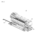
- Fig. 1 shows appearance of a main body of the printing apparatus 10.
- Fig. 2 shows an attaching state that an ink receiving unit 14 is attached to the main body 12 of the printing apparatus 10.
- Figs. 3(a), 3(b) are enlarged views of attached portions of the ink receiving unit 14.
- Fig. 3(a) is an enlarged view of one end side of the ink receiving unit 14.
- Fig. 3(b) is an enlarged view of the other end side of the ink receiving unit 14.
- the printing apparatus 10 is an inkjet printer of a scanning type in which the printing is conducted while reciprocating an inkjet head thereof in a previously set main scanning direction.
- the printing apparatus 10 is a printing apparatus of a paper-moving type in which the printing is conducted while feeding a medium in a sub scanning direction perpendicular to the main scanning direction.
- the printing apparatus 10 is a printing apparatus for printing on a medium through which ink ejected onto the surface of the medium is allowed to seep to the back side of the medium and comprises a main body 12 and an ink receiving unit 14.
- the medium through which ink ejected onto the surface of the medium is allowed to seep to the back side of the medium is a medium allowing ink ejected from an inkjet head to drip from the back thereof, for example, mesh-like media and fibrous media.
- the main body 12 is a main portion of the printing apparatus 10 for printing on the medium.
- the ink receiving unit 14 is attached to the main body 12.
- the main body 12 has an inkjet head 16 and a controller 18 therein.
- the inkjet head 16 is a print head for ejecting ink in accordance with the inkjet method.
- the controller 18 is a control device such as a CPU for controlling respective components of the printing apparatus 10. Though only some components have been described in the above for ease of explanation, the main body 12 suitably comprises components required for printing, such as a feeding member for feeding media.
- the ink receiving unit 14 is a member for receiving ink droplets dripping from the back of the medium and is detachably attached to the main body 12.
- the ink receiving unit 14 is mounted such that the longitudinal direction thereof extends parallel to the main scanning direction.
- an ink receiver which receives ink droplets in the ink receiving unit 14 faces the inkjet head 16 across a medium.
- the ink receiver spreads in a wide area larger than the width of the medium in the main scanning direction. According to this embodiment, ink droplets dripping from the back of the medium can be suitably received.
- the arrangement for receiving ink droplets may not be structured as a unit and an arrangement corresponding to the ink receiving unit 14 may be formed in the main body 12.
- the inkjet head 16 stands by at a position outside of the ink receiving unit 14.
- the inkjet head 16 reciprocates in the main scanning direction.
- the ink receiver of the ink receiving unit 14 and the inkjet head 16 face each other across the medium.
- the distance between the inkjet head 16 and the ink receiver is in a range of from 3 to 10 mm, for example, and more preferably from 5 to 7 mm.
- ink droplets dripping from the back of the medium can be suitably received with the medium laying between the inkjet head 16 and the ink receiver.
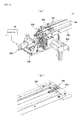
- Figs. 4(a), 4(b) show a first example of specific structure of the ink receiving unit 14.
- Fig. 4(a) shows the structure of one end side of the ink receiving unit 14 as well as some parts of the main body 12 (see Fig. 1 ).
- Fig. 4(b) shows the structure of the other side of the ink receiving unit 14.
- the ink receiving unit 14 has an ink receiver 102, a wiper member 104, and some parts composing a driving section 106.
- the ink receiver 102 is a gutter-like waste ink tray for receiving ink droplets dripping from the back of the medium.
- the ink receiver 102 extends in the main scanning direction when the ink receiving unit 14 is attached to the main body 12.
- Formed on one end of the ink receiver 102 is an ink discharge port 202.
- the ink discharge port 202 is an opening for discharging waste ink received by the ink receiver 102 to the outside.
- the ink discharge port 202 is connected to a discharge passage 204 formed in the main body 12 so that waste ink is discharged by flowing the waste ink through the discharge passage 204.
- the ink discharge port 202 is formed at the end, near the driving section 106, of the ink receiver 102. Accordingly, the ink receiving unit 14 collects waste ink by moving the wiper member 104 in a direction toward the driving section 106. Another ink discharge port 202 may also be formed at the end, far from the driving section 106, of the ink receiver 102. With this structure, waste ink can be also collected by moving the wiper member 104 in a direction apart from the driving section 106.
- the wiper member 104 is an example of ink removing means for removing the ink in the ink receiver 102 from the ink receiver 102.
- the wiper member 104 slides in the main scanning direction corresponding to the longitudinal direction of the ink receiver 102.
- the wiper member 104 removes the ink in the ink receiver 102 by sliding and traveling along the gutter-like ink receiver 102. Therefore, the wiper member 104 functions as a waste ink wiper to clean the ink receiver 102 by forcibly removing the ink in the ink receiver 102. In this manner, this example can suitably remove the ink in the ink receiver 102.
- the wiper member 104 has a substantially T-like shape and has a widespread portion 302 extending in the width direction of a gutter-like groove of the ink receiver 102 and a wire connecting portion 304 projecting from the center of the widespread portion toward one end of the ink receiver 102.
- the widespread portion 302 is a portion corresponding to a head portion of the character T and has a structure of spreading in the width direction of the ink receiver 102 so as to enable the widespread portion 302 to push out the ink in the ink receiver 102 according to the sliding of the wiper member 104.
- the wire connecting portion 304 is a portion corresponding to a leg portion of the character T and is connected to a wire 108 for driving the wiper member 104. Therefore, the wiper member 104 is moved along the ink receiver 102 when subjected to force of the driving section 106 through the wire 108.
- the driving section 106 has a motor, gears, and the like for driving the wiper member 104.
- the driving section 106 has a driving motor 206 and a wire drum 208.
- the driving motor 206 rotates the wire drum 208 according to a command from the controller 18.
- the wire drum 208 is a drum on which the wire 108 is wound and moves the wire 108 according to the output power of the driving motor 206. Therefore, the driving section 106 drives the wiper member 104 via the wire 108 according to the command of the controller 18.
- the driving section 106 also comprises gears and/or pulleys, for example.
- the driving section 106 is structured by combining respective components on the main body 12 and the ink receiving unit 14. Specific structure of the driving section 106 will be further described later.
- the wire 108 is a driving wire transmitting the power of the driving section 106 to the wiper member 104.
- the wire 108 is tensioned to extend in the longitudinal direction of the ink receiver 102 by pulleys of the driving section 106 in the ink receiver 102.
- the wire 108 is tensioned to extend to make a round trip (loop) in the ink receiver 102 by and between the wire drum 208 and the pulley, disposed on one end side of the ink receiving unit 104, of the driving section 106 and a plurality of pulleys, disposed on the other end side of the ink receiving unit 104, of the driving section 106.
- a part corresponding to one way of the round trip of the wire 108 is tensioned to extend along the center in the width direction of the ink receiver 102.
- the wire connecting portion 304 of the wiper member 104 is attached to the part of the wire extending along the center.
- the wire 108 holds the T-like wiper member 104 at the center of the wiper member 104 (center holding).
- the wiper member 104 is held at its center of gravity so that the wiper member 104 does not practically rattle and the wiper member 104 can stably travel.
- the wiper member 104 As a method for holding the wiper member 104 using the wire 108, there is conceivable a method of holding one side of the wiper member 104 (cantilever holding) instead of center holding.
- the cantilever holding makes the wiper member 104 more easily rattle so that it may be difficult to drive the wiper 104 to stably travel.
- the apparatus may be increased in size and in cost. Further, the workability may become worse.
- the wiper member 104 is held at the center, thereby driving the wiper member 104 to stably travel without increasing the size of the apparatus.
- ink received by the ink receiver 102 can be suitably removed by the wiper member 104. Therefore, it is possible to suitably prevent the ink in the ink receiver 102 from being stacked or solidified. Since the ink receiver 102 can be automatically cleaned by movement of the wiper member 104, the cleaning time and labor for manually cleaning the ink receiver 102 can be suitably reduced. Moreover, it is possible to conduct the collection of waste ink all over the printing area at a side behind the medium, thereby removing the waste ink at the same time of printing, for example. Therefore, stacking and solidification of ink can be suitably prevented.
- the controller 18 controls the wiper member 104 to operate, for example, when the printing apparatus 10 (see Fig. 1 ) conducts printing operation. Accordingly, the wiper member 104 removes ink in real time during the printing operation.
- the controller 18 may control the wiper member 104 to operate in response to depression of a button or the like during maintenance of the printing apparatus, for example. In this case, the depression of the button or the like makes the wiper member 104 start to remove ink.
- the controller 18 may control the wiper member 104 to operate at regular time intervals for example when the printer apparatus is in stand-by state (sleeping state). Accordingly, it is possible to suitably prevent the solidification of residual ink in an unattended environment, i.e. without any user.
- the controller 18 changes the stand-by position of the wiper member 104 for every operation in which the wiper member 104 travels a predetermined amount.
- the stand-by position of the wiper member 104 is a position within the ink receiver where the wiper member 104 stands by when it is not in operation.
- the controller 18 changes the stand-by position in a random manner every time when stopping the wiper member 104 after the operation.
- ink adhering to a portion directly below the wiper member 104 may be solidified in the stand-by position. According to this example, however, even though the ink adhering to a portion directly below the wiper member 104 is solidified, the position where ink is solidified is distributable. Therefore, it is possible to suitably prevent the problem caused due to stacking of solidified ink. Further, it is therefore possible to suitably remove waste ink.
- Fig. 5 and Fig. 6 are perspective views schematically showing an example of specific structure of the driving section 106 with the ink receiver 102, the wiper member 104, and the wire 108.
- Fig. 5 is a perspective view of an upper side of the ink receiver 102 as seen diagonally from rear left.
- Fig. 6 is a perspective view of a bottom side of the ink receiver 102 as seen diagonally from front right.
- the driving section 106 comprises a driving motor 206, a motor pinion gear, a drive gear A, a power transmitting shaft, a drive gear B, a motor timing control fin, a torque limiter, a motor control photosensor, two idler gears, a drum drive gear, a drum shaft, a wire drum 208, pulleys C, a turn-around pulley A, and turn-around pulleys B.
- the driving motor 206, the motor pinion gear, the drive gear A, the power transmitting shaft, the drive gear B, the motor timing control fin, the torque limiter, the motor control photosensor, and the two idler gears are disposed on the main body 12 (see Fig. 1 ).
- the drum drive gear, the drum shaft, the wire drum 208, the pulleys C, the turn-around pulley A, and the turn-around pulleys B are disposed on the ink receiving unit 14.
- These components other than the turn-around pulley A and the turn-around pulleys B are disposed on one end side of the ink receiving unit 14.
- the turn-around pulley A and the turn-around pulleys B are disposed on the other end side of the ink receiving unit 14, i.e. the opposite side of the ink receiver 102.
- the driving motor 206 is a motor which rotates in response to command of the controller 18.
- the motor pinion gear is attached to the rotary shaft of the driving motor 206 so that the motor pinion gear rotates according to the rotation of the driving motor 206.
- the drive gear A meshes with the motor pinion gear so that the drive gear A rotates according to the rotation of the motor pinion gear.
- the power transmitting shaft is a shaft for holding the drive gear A.
- the power transmitting shaft also holds the drive gear B, the torque limiter, and the motor timing control fin coaxially with the drive gear A. Accordingly, the drive gear B and the motor timing control fin rotate according to the rotation of the drive gear A.
- the torque limiter limits the rotary torque of the drive gear A.
- the motor control photosensor is a sensor for detecting the rotation speed of the motor timing control fin and feeding back the detection result to the controller 18. Based on the rotation speed detected by the motor control photosensor, the controller 18 controls the output to the driving motor 206.
- the two idler gears are gears for alignment of the drum drive gear.
- the two idler gears mesh with the drum drive gear on the ink receiving unit 14 and the drive gear B on the main body 12. Accordingly, the drum drive gear rotates according to the rotation of the drive gear B.
- the drum shaft is a shaft for holding the drum drive gear and the wire drum 208 coaxially.
- the wire drum 208 is a drum on which the wire 108 is wound. As the wire drum 208 rotates according to the rotation of the drum drive gear, the wire drum 208 moves the wire 108, to which the wiper member 104 is attached, according to the output of the driving motor 206.
- the pulleys C are disposed between the wire drum and the ink receiver 102 and cooperate together with the turn-around pulley A and the turn-around pulleys B, arranged on the opposite side of the ink receiver 102, to position the wire 108 such that the wire 108 extends along the ink receiver 102 with some tension.
- the wiper member 104 can be suitably operated by the driving section 106 moving the wire 108. Therefore, the ink in the ink receiver 102 can be suitably removed.
- the driving motor 206 and the wire drum 208 are positioned such that their rotary shafts extend parallel to each other. In addition, the rotary shafts of the respective gears between the driving motor 206 and the wire drum 208 also extend parallel to each other. According to this example, the power of the driving motor can be reliably transmitted to the wire drum with a simple structure.
- one way, to which the wiper member 104 is attached, of a round trip (loop) of the wire 108 tensioned in the ink receiver 102 is set to the center in the width direction of the ink receiver 102.
- the pulleys C are arranged between the wire drum and the ink receiver 102, and the turn-around pulley A and the turn-around pulleys B are disposed on the opposite side of the ink receiver 102 so that the other way to which the wiper member 104 is not attached (hereinafter, sometimes referred to as "returning way") is set near the center in the width direction of the ink receiver 102 so that the returning way is located above the wire connecting portion 304 of the wiper member 104.
- the widespread portion 302 of the wiper member 104 expands in the width direction of the ink receiver 102. Therefore, the wiper member 104 easily contacts with the returning way of the wire 108 at any portion. As the wiper member 104 and the returning way of the wire 108 contact with each other, the wiper member 104 is subjected to the force in the direction opposite to the advancing direction. If the returning way of the wire 108 is apart from the center in the width direction of the ink receiver 102, large rotary torque is applied to the wiper 104 so that the wiper member 104 may easily rattle during the operation when the wiper member 104 and the returning way of the wire 108 contact with each other.
- the returning way of the wire 108 is set near the center in the width direction of the ink receiver 102 such that the returning way of the wire 108 is located above the wire connecting portion 304 of the wiper member 104.
- the rattling during the operation can be suitably prevented so that the wiper member 104 can suitably travel. This enables further suitable removal of the ink in the ink receiver 102.
- Figs. 7(a), 7(b) show a second example of specific structure of the ink receiving unit 14.
- Fig. 7(a) shows the structure of one end side of the ink receiving unit 14 as well as the structure of some components of the main body 12 (see Fig. 1 ).
- Fig. 7(b) shows the structure of the other end side of the ink receiving unit 14.
- components with the same reference numerals as Figs. 4(a), 4(b) are the same components as those in the structure shown in Figs. 4(a), 4(b) .
- the rotary shaft of the driving motor 206 of the driving section 106 extends parallel to the main scanning direction of the printing apparatus 10 (see Fig. 1 ).
- This arrangement can achieve reduction of size in the depth direction of the driving section 106, i.e. the sub scanning direction of the printing apparatus 10. Further, this arrangement can prevent the printing apparatus 10 from growing in size due to installation of the ink receiving unit 14, for example.
- no pulley is arranged between the wire drum 208 and the ink receiver 102.
- only one turn-around pulley is arranged on the opposite side of the ink receiver 102. Accordingly, this arrangement can reduce the number of components of the driving section 106. Further, this arrangement can suitably reduce the cost of the ink receiving unit 14, for example.
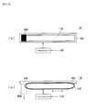
- Figs. 8(a), 8(b) schematically show a variation of the structure of the ink receiving unit 14.
- Fig. 8(a) is a top view of the ink receiving unit 14.
- Fig. 8(b) is a sectional side view of the ink receiving unit 14.
- components with the same reference numerals as Figs. 4(a), 4(b) are the same components as those in the structure shown in Figs. 4(a), 4(b) .
- the ink receiving unit 14 has a belt member 110 as the ink removing means, instead of the wiper member 104 (see Figs. 4(a), 4(b) ).
- the belt member 110 is a band-like member having a movable ink receiving surface. In a state that the ink receiving unit 14 is attached to the main body 12, the belt member 110 extends in the main scanning direction over the bottom surface of the gutter-like ink receiver 102.
- the driving section 106 moves the belt member 110 by a mechanism similar to that for a belt of a moving walkway, a belt conveyor, or the like. Therefore, the belt member 110 moves along the bottom surface of the ink receiver 102 so as to remove the ink in the receiver 102. Also according to this example, the ink in the ink receiver 102 can be suitably removed.
Landscapes
- Engineering & Computer Science (AREA)
- Quality & Reliability (AREA)
- Ink Jet (AREA)
- Dot-Matrix Printers And Others (AREA)
- Glass Compositions (AREA)
- Noodles (AREA)
Applications Claiming Priority (2)
| Application Number | Priority Date | Filing Date | Title |
|---|---|---|---|
| JP2007327614A JP2009148943A (ja) | 2007-12-19 | 2007-12-19 | 印刷装置 |
| EP08291115A EP2072265B1 (de) | 2007-12-19 | 2008-11-27 | Druckvorrichtung |
Related Parent Applications (1)
| Application Number | Title | Priority Date | Filing Date |
|---|---|---|---|
| EP08291115.7 Division | 2008-11-27 |
Publications (2)
| Publication Number | Publication Date |
|---|---|
| EP2184169A1 true EP2184169A1 (de) | 2010-05-12 |
| EP2184169B1 EP2184169B1 (de) | 2011-05-18 |
Family
ID=40521554
Family Applications (2)
| Application Number | Title | Priority Date | Filing Date |
|---|---|---|---|
| EP08291115A Not-in-force EP2072265B1 (de) | 2007-12-19 | 2008-11-27 | Druckvorrichtung |
| EP10154998A Active EP2184169B1 (de) | 2007-12-19 | 2008-11-27 | Druckvorrichtung |
Family Applications Before (1)
| Application Number | Title | Priority Date | Filing Date |
|---|---|---|---|
| EP08291115A Not-in-force EP2072265B1 (de) | 2007-12-19 | 2008-11-27 | Druckvorrichtung |
Country Status (7)
| Country | Link |
|---|---|
| US (1) | US8057029B2 (de) |
| EP (2) | EP2072265B1 (de) |
| JP (1) | JP2009148943A (de) |
| KR (1) | KR101000849B1 (de) |
| CN (1) | CN101480873B (de) |
| AT (2) | ATE509769T1 (de) |
| DE (1) | DE602008006339D1 (de) |
Families Citing this family (3)
| Publication number | Priority date | Publication date | Assignee | Title |
|---|---|---|---|---|
| USD611093S1 (en) * | 2008-02-29 | 2010-03-02 | Mimaki Engineering Co., Ltd. | Ink receiving unit |
| CN105522824B (zh) * | 2015-12-21 | 2017-07-21 | 东莞统领新型材料纳米科技有限公司 | 一种数码印花机 |
| CN109703198B (zh) * | 2017-10-25 | 2020-12-29 | 北大方正集团有限公司 | 印刷机的喷头清洗系统及印刷机的喷头清洗方法 |
Citations (4)
| Publication number | Priority date | Publication date | Assignee | Title |
|---|---|---|---|---|
| JPH1148498A (ja) * | 1997-07-30 | 1999-02-23 | Tec Corp | インクジェットプリンタ |
| US20030030692A1 (en) * | 2001-08-10 | 2003-02-13 | Canon Kabushiki Kaisha | Ink jet recording apparatus |
| EP1433612A1 (de) * | 2002-12-27 | 2004-06-30 | Hewlett-Packard Development Company, L.P. | Tintenstrahldrucken |
| EP1537998A1 (de) * | 2003-12-05 | 2005-06-08 | Océ-Technologies B.V. | Vorrichtung und Verfahren zum Handhaben von Tintentropfen |
Family Cites Families (5)
| Publication number | Priority date | Publication date | Assignee | Title |
|---|---|---|---|---|
| JP4333969B2 (ja) * | 1999-07-23 | 2009-09-16 | 株式会社ミマキエンジニアリング | インクジェットプロッタ |
| JP2002192756A (ja) | 2000-12-26 | 2002-07-10 | Mimaki Engineering Co Ltd | インクジェットプリンタ |
| US6742864B2 (en) | 2002-04-30 | 2004-06-01 | Hewlett-Packard Development Company, L.P. | Waste ink removal system |
| JP2004351709A (ja) | 2003-05-28 | 2004-12-16 | Konica Minolta Medical & Graphic Inc | インクジェットプリンタ |
| JP2007185860A (ja) * | 2006-01-13 | 2007-07-26 | Seiko Epson Corp | 捕捉部材及びインクジェットプリンタ |
-
2007
- 2007-12-19 JP JP2007327614A patent/JP2009148943A/ja active Pending
-
2008
- 2008-07-16 KR KR1020080068983A patent/KR101000849B1/ko not_active Expired - Fee Related
- 2008-09-29 US US12/240,514 patent/US8057029B2/en not_active Expired - Fee Related
- 2008-11-27 AT AT10154998T patent/ATE509769T1/de not_active IP Right Cessation
- 2008-11-27 EP EP08291115A patent/EP2072265B1/de not_active Not-in-force
- 2008-11-27 EP EP10154998A patent/EP2184169B1/de active Active
- 2008-11-27 DE DE602008006339T patent/DE602008006339D1/de active Active
- 2008-11-27 AT AT08291115T patent/ATE506193T1/de not_active IP Right Cessation
- 2008-11-28 CN CN2008101793147A patent/CN101480873B/zh not_active Expired - Fee Related
Patent Citations (4)
| Publication number | Priority date | Publication date | Assignee | Title |
|---|---|---|---|---|
| JPH1148498A (ja) * | 1997-07-30 | 1999-02-23 | Tec Corp | インクジェットプリンタ |
| US20030030692A1 (en) * | 2001-08-10 | 2003-02-13 | Canon Kabushiki Kaisha | Ink jet recording apparatus |
| EP1433612A1 (de) * | 2002-12-27 | 2004-06-30 | Hewlett-Packard Development Company, L.P. | Tintenstrahldrucken |
| EP1537998A1 (de) * | 2003-12-05 | 2005-06-08 | Océ-Technologies B.V. | Vorrichtung und Verfahren zum Handhaben von Tintentropfen |
Also Published As
| Publication number | Publication date |
|---|---|
| EP2072265A1 (de) | 2009-06-24 |
| ATE506193T1 (de) | 2011-05-15 |
| DE602008006339D1 (de) | 2011-06-01 |
| EP2072265B1 (de) | 2011-04-20 |
| US8057029B2 (en) | 2011-11-15 |
| EP2184169B1 (de) | 2011-05-18 |
| CN101480873A (zh) | 2009-07-15 |
| ATE509769T1 (de) | 2011-06-15 |
| CN101480873B (zh) | 2010-12-15 |
| KR101000849B1 (ko) | 2010-12-14 |
| JP2009148943A (ja) | 2009-07-09 |
| US20090160902A1 (en) | 2009-06-25 |
| KR20090067023A (ko) | 2009-06-24 |
Similar Documents
| Publication | Publication Date | Title |
|---|---|---|
| EP0911170B1 (de) | Tintenstrahldrucker mit einer verbesserten Reinigungseinheit | |
| EP2072264B1 (de) | Tintenempfangseinheit und Druckvorrichtung | |
| US20080143781A1 (en) | Inkjet printing apparatus and control method for inkjet printing apparatus | |
| JP5899968B2 (ja) | 画像形成装置 | |
| JP6194576B2 (ja) | 液体噴射装置 | |
| EP2072265B1 (de) | Druckvorrichtung | |
| JP6418207B2 (ja) | 液体噴射装置 | |
| JP6028913B2 (ja) | 液体噴射装置 | |
| EP1782956B1 (de) | Tintenstrahlaufzeichungsgerät | |
| JP2009269327A (ja) | インクジェット記録装置 | |
| JP2010058473A (ja) | ヘッドクリーニング装置及びこれを用いた画像形成装置 | |
| JPH08142345A (ja) | インクジェット装置 | |
| JP3922222B2 (ja) | 液体吐出装置及びその制御方法 | |
| JP4748123B2 (ja) | インクジェット記録装置 | |
| JP2009132107A (ja) | インクジェット記録装置および制御プログラム | |
| KR20140092618A (ko) | 문서 출력 장치 | |
| JP2020097150A (ja) | インクジェット印刷装置 | |
| JP2008221525A (ja) | 液体噴射装置、画像記録装置、および、画像記録装置の制御方法 | |
| JP2019111719A (ja) | インクジェット記録装置およびその清掃方法 | |
| JP2007098876A (ja) | インクジェットプリンタ | |
| JPH1142792A (ja) | インクジェットプリンタ |
Legal Events
| Date | Code | Title | Description |
|---|---|---|---|
| PUAI | Public reference made under article 153(3) epc to a published international application that has entered the european phase |
Free format text: ORIGINAL CODE: 0009012 |
|
| AC | Divisional application: reference to earlier application |
Ref document number: 2072265 Country of ref document: EP Kind code of ref document: P |
|
| AK | Designated contracting states |
Kind code of ref document: A1 Designated state(s): AT BE BG CH CY CZ DE DK EE ES FI FR GB GR HR HU IE IS IT LI LT LU LV MC MT NL NO PL PT RO SE SI SK TR |
|
| AX | Request for extension of the european patent |
Extension state: AL BA MK RS |
|
| GRAP | Despatch of communication of intention to grant a patent |
Free format text: ORIGINAL CODE: EPIDOSNIGR1 |
|
| 17P | Request for examination filed |
Effective date: 20101112 |
|
| RIC1 | Information provided on ipc code assigned before grant |
Ipc: B41J 2/17 20060101AFI20101203BHEP |
|
| GRAS | Grant fee paid |
Free format text: ORIGINAL CODE: EPIDOSNIGR3 |
|
| GRAA | (expected) grant |
Free format text: ORIGINAL CODE: 0009210 |
|
| REG | Reference to a national code |
Ref country code: GB Ref legal event code: FG4D |
|
| REG | Reference to a national code |
Ref country code: CH Ref legal event code: EP |
|
| REG | Reference to a national code |
Ref country code: IE Ref legal event code: FG4D |
|
| REG | Reference to a national code |
Ref country code: DE Ref legal event code: R096 Ref document number: 602008007065 Country of ref document: DE Effective date: 20110630 |
|
| REG | Reference to a national code |
Ref country code: NL Ref legal event code: VDEP Effective date: 20110518 |
|
| PG25 | Lapsed in a contracting state [announced via postgrant information from national office to epo] |
Ref country code: SE Free format text: LAPSE BECAUSE OF FAILURE TO SUBMIT A TRANSLATION OF THE DESCRIPTION OR TO PAY THE FEE WITHIN THE PRESCRIBED TIME-LIMIT Effective date: 20110518 Ref country code: LT Free format text: LAPSE BECAUSE OF FAILURE TO SUBMIT A TRANSLATION OF THE DESCRIPTION OR TO PAY THE FEE WITHIN THE PRESCRIBED TIME-LIMIT Effective date: 20110518 Ref country code: NO Free format text: LAPSE BECAUSE OF FAILURE TO SUBMIT A TRANSLATION OF THE DESCRIPTION OR TO PAY THE FEE WITHIN THE PRESCRIBED TIME-LIMIT Effective date: 20110818 Ref country code: HR Free format text: LAPSE BECAUSE OF FAILURE TO SUBMIT A TRANSLATION OF THE DESCRIPTION OR TO PAY THE FEE WITHIN THE PRESCRIBED TIME-LIMIT Effective date: 20110518 Ref country code: PT Free format text: LAPSE BECAUSE OF FAILURE TO SUBMIT A TRANSLATION OF THE DESCRIPTION OR TO PAY THE FEE WITHIN THE PRESCRIBED TIME-LIMIT Effective date: 20110919 |
|
| PG25 | Lapsed in a contracting state [announced via postgrant information from national office to epo] |
Ref country code: SI Free format text: LAPSE BECAUSE OF FAILURE TO SUBMIT A TRANSLATION OF THE DESCRIPTION OR TO PAY THE FEE WITHIN THE PRESCRIBED TIME-LIMIT Effective date: 20110518 Ref country code: ES Free format text: LAPSE BECAUSE OF FAILURE TO SUBMIT A TRANSLATION OF THE DESCRIPTION OR TO PAY THE FEE WITHIN THE PRESCRIBED TIME-LIMIT Effective date: 20110829 Ref country code: IS Free format text: LAPSE BECAUSE OF FAILURE TO SUBMIT A TRANSLATION OF THE DESCRIPTION OR TO PAY THE FEE WITHIN THE PRESCRIBED TIME-LIMIT Effective date: 20110918 Ref country code: LV Free format text: LAPSE BECAUSE OF FAILURE TO SUBMIT A TRANSLATION OF THE DESCRIPTION OR TO PAY THE FEE WITHIN THE PRESCRIBED TIME-LIMIT Effective date: 20110518 Ref country code: FI Free format text: LAPSE BECAUSE OF FAILURE TO SUBMIT A TRANSLATION OF THE DESCRIPTION OR TO PAY THE FEE WITHIN THE PRESCRIBED TIME-LIMIT Effective date: 20110518 Ref country code: GR Free format text: LAPSE BECAUSE OF FAILURE TO SUBMIT A TRANSLATION OF THE DESCRIPTION OR TO PAY THE FEE WITHIN THE PRESCRIBED TIME-LIMIT Effective date: 20110819 Ref country code: BE Free format text: LAPSE BECAUSE OF FAILURE TO SUBMIT A TRANSLATION OF THE DESCRIPTION OR TO PAY THE FEE WITHIN THE PRESCRIBED TIME-LIMIT Effective date: 20110518 Ref country code: CY Free format text: LAPSE BECAUSE OF FAILURE TO SUBMIT A TRANSLATION OF THE DESCRIPTION OR TO PAY THE FEE WITHIN THE PRESCRIBED TIME-LIMIT Effective date: 20110518 Ref country code: AT Free format text: LAPSE BECAUSE OF FAILURE TO SUBMIT A TRANSLATION OF THE DESCRIPTION OR TO PAY THE FEE WITHIN THE PRESCRIBED TIME-LIMIT Effective date: 20110518 |
|
| PG25 | Lapsed in a contracting state [announced via postgrant information from national office to epo] |
Ref country code: NL Free format text: LAPSE BECAUSE OF FAILURE TO SUBMIT A TRANSLATION OF THE DESCRIPTION OR TO PAY THE FEE WITHIN THE PRESCRIBED TIME-LIMIT Effective date: 20110518 |
|
| PG25 | Lapsed in a contracting state [announced via postgrant information from national office to epo] |
Ref country code: EE Free format text: LAPSE BECAUSE OF FAILURE TO SUBMIT A TRANSLATION OF THE DESCRIPTION OR TO PAY THE FEE WITHIN THE PRESCRIBED TIME-LIMIT Effective date: 20110518 Ref country code: CZ Free format text: LAPSE BECAUSE OF FAILURE TO SUBMIT A TRANSLATION OF THE DESCRIPTION OR TO PAY THE FEE WITHIN THE PRESCRIBED TIME-LIMIT Effective date: 20110518 |
|
| PG25 | Lapsed in a contracting state [announced via postgrant information from national office to epo] |
Ref country code: PL Free format text: LAPSE BECAUSE OF FAILURE TO SUBMIT A TRANSLATION OF THE DESCRIPTION OR TO PAY THE FEE WITHIN THE PRESCRIBED TIME-LIMIT Effective date: 20110518 Ref country code: SK Free format text: LAPSE BECAUSE OF FAILURE TO SUBMIT A TRANSLATION OF THE DESCRIPTION OR TO PAY THE FEE WITHIN THE PRESCRIBED TIME-LIMIT Effective date: 20110518 |
|
| PLBE | No opposition filed within time limit |
Free format text: ORIGINAL CODE: 0009261 |
|
| STAA | Information on the status of an ep patent application or granted ep patent |
Free format text: STATUS: NO OPPOSITION FILED WITHIN TIME LIMIT |
|
| 26N | No opposition filed |
Effective date: 20120221 |
|
| REG | Reference to a national code |
Ref country code: DE Ref legal event code: R097 Ref document number: 602008007065 Country of ref document: DE Effective date: 20120221 |
|
| PG25 | Lapsed in a contracting state [announced via postgrant information from national office to epo] |
Ref country code: MC Free format text: LAPSE BECAUSE OF NON-PAYMENT OF DUE FEES Effective date: 20111130 |
|
| REG | Reference to a national code |
Ref country code: IE Ref legal event code: MM4A |
|
| PG25 | Lapsed in a contracting state [announced via postgrant information from national office to epo] |
Ref country code: IE Free format text: LAPSE BECAUSE OF NON-PAYMENT OF DUE FEES Effective date: 20111127 |
|
| PG25 | Lapsed in a contracting state [announced via postgrant information from national office to epo] |
Ref country code: MT Free format text: LAPSE BECAUSE OF FAILURE TO SUBMIT A TRANSLATION OF THE DESCRIPTION OR TO PAY THE FEE WITHIN THE PRESCRIBED TIME-LIMIT Effective date: 20110518 |
|
| PG25 | Lapsed in a contracting state [announced via postgrant information from national office to epo] |
Ref country code: LU Free format text: LAPSE BECAUSE OF NON-PAYMENT OF DUE FEES Effective date: 20111127 |
|
| PG25 | Lapsed in a contracting state [announced via postgrant information from national office to epo] |
Ref country code: BG Free format text: LAPSE BECAUSE OF FAILURE TO SUBMIT A TRANSLATION OF THE DESCRIPTION OR TO PAY THE FEE WITHIN THE PRESCRIBED TIME-LIMIT Effective date: 20110818 |
|
| REG | Reference to a national code |
Ref country code: CH Ref legal event code: PL |
|
| GBPC | Gb: european patent ceased through non-payment of renewal fee |
Effective date: 20121127 |
|
| PG25 | Lapsed in a contracting state [announced via postgrant information from national office to epo] |
Ref country code: LI Free format text: LAPSE BECAUSE OF NON-PAYMENT OF DUE FEES Effective date: 20121130 Ref country code: CH Free format text: LAPSE BECAUSE OF NON-PAYMENT OF DUE FEES Effective date: 20121130 |
|
| PG25 | Lapsed in a contracting state [announced via postgrant information from national office to epo] |
Ref country code: TR Free format text: LAPSE BECAUSE OF FAILURE TO SUBMIT A TRANSLATION OF THE DESCRIPTION OR TO PAY THE FEE WITHIN THE PRESCRIBED TIME-LIMIT Effective date: 20110518 |
|
| PG25 | Lapsed in a contracting state [announced via postgrant information from national office to epo] |
Ref country code: HU Free format text: LAPSE BECAUSE OF FAILURE TO SUBMIT A TRANSLATION OF THE DESCRIPTION OR TO PAY THE FEE WITHIN THE PRESCRIBED TIME-LIMIT Effective date: 20110518 |
|
| PG25 | Lapsed in a contracting state [announced via postgrant information from national office to epo] |
Ref country code: GB Free format text: LAPSE BECAUSE OF NON-PAYMENT OF DUE FEES Effective date: 20121127 |
|
| REG | Reference to a national code |
Ref country code: FR Ref legal event code: PLFP Year of fee payment: 8 |
|
| REG | Reference to a national code |
Ref country code: FR Ref legal event code: PLFP Year of fee payment: 9 |
|
| PGFP | Annual fee paid to national office [announced via postgrant information from national office to epo] |
Ref country code: FR Payment date: 20161014 Year of fee payment: 9 |
|
| REG | Reference to a national code |
Ref country code: FR Ref legal event code: ST Effective date: 20180731 |
|
| PG25 | Lapsed in a contracting state [announced via postgrant information from national office to epo] |
Ref country code: FR Free format text: LAPSE BECAUSE OF NON-PAYMENT OF DUE FEES Effective date: 20171130 |
|
| PGFP | Annual fee paid to national office [announced via postgrant information from national office to epo] |
Ref country code: DE Payment date: 20181113 Year of fee payment: 11 |
|
| PGFP | Annual fee paid to national office [announced via postgrant information from national office to epo] |
Ref country code: IT Payment date: 20181122 Year of fee payment: 11 |
|
| REG | Reference to a national code |
Ref country code: DE Ref legal event code: R119 Ref document number: 602008007065 Country of ref document: DE |
|
| PG25 | Lapsed in a contracting state [announced via postgrant information from national office to epo] |
Ref country code: IT Free format text: LAPSE BECAUSE OF NON-PAYMENT OF DUE FEES Effective date: 20191127 Ref country code: DE Free format text: LAPSE BECAUSE OF NON-PAYMENT OF DUE FEES Effective date: 20200603 |