EP2184228A1 - Système de contrôle et procédé de séparation de l'articulation d'une barre de commande - Google Patents
Système de contrôle et procédé de séparation de l'articulation d'une barre de commande Download PDFInfo
- Publication number
- EP2184228A1 EP2184228A1 EP08790600A EP08790600A EP2184228A1 EP 2184228 A1 EP2184228 A1 EP 2184228A1 EP 08790600 A EP08790600 A EP 08790600A EP 08790600 A EP08790600 A EP 08790600A EP 2184228 A1 EP2184228 A1 EP 2184228A1
- Authority
- EP
- European Patent Office
- Prior art keywords
- control lever
- sensor
- force
- stacking
- stack
- Prior art date
- Legal status (The legal status is an assumption and is not a legal conclusion. Google has not performed a legal analysis and makes no representation as to the accuracy of the status listed.)
- Withdrawn
Links
Images




Classifications
-
- B—PERFORMING OPERATIONS; TRANSPORTING
- B64—AIRCRAFT; AVIATION; COSMONAUTICS
- B64C—AEROPLANES; HELICOPTERS
- B64C13/00—Control systems or transmitting systems for actuating flying-control surfaces, lift-increasing flaps, air brakes, or spoilers
- B64C13/02—Initiating means
- B64C13/04—Initiating means actuated personally
- B64C13/12—Dual control apparatus
-
- Y—GENERAL TAGGING OF NEW TECHNOLOGICAL DEVELOPMENTS; GENERAL TAGGING OF CROSS-SECTIONAL TECHNOLOGIES SPANNING OVER SEVERAL SECTIONS OF THE IPC; TECHNICAL SUBJECTS COVERED BY FORMER USPC CROSS-REFERENCE ART COLLECTIONS [XRACs] AND DIGESTS
- Y02—TECHNOLOGIES OR APPLICATIONS FOR MITIGATION OR ADAPTATION AGAINST CLIMATE CHANGE
- Y02T—CLIMATE CHANGE MITIGATION TECHNOLOGIES RELATED TO TRANSPORTATION
- Y02T50/00—Aeronautics or air transport
- Y02T50/40—Weight reduction
Definitions
- the present invention relates to a flight control system and a method of separating control lever linkage where two control levers are linked with each other by a link mechanism.
- this application claims priority from Japanese Patent Application No. 2008-039342 , and the disclosure of Japanese Patent Application No. 2008-039342 is incorporated herein in its entirety by reference.
- a control lever includes a wheel and a column manipulated by a pilot.
- the pilot can execute an operating input of a rolling direction (a roll input) by rotating the wheel and an operating input of a pitching direction (a pitch input) by pushing and pulling the column.
- the roll input and the pitch input are converted into electric signals by displacement sensors of the wheel and column, and are inputted to a fight control computer as a pitch command and a roll command (collectively referred to as an operating command).
- a control law calculation is executed on the basis of this operating command in the flight control computer and control surfaces are driven by actuators which are controlled based on the calculation result, and thus a fuselage (for example, an aircraft) can be controlled.
- Japanese Laid-Open Patent Application JP-P 2003-335496 A discloses a flight control system of an aircraft using a fly-by-wire described above.
- control levers on a pilot side and on a co-pilot side are mechanically linked and the flight control can be carried out if the input is executed from either one of the control levers. Since a force (an operating input) applied to one of the control levers is transmitted to the other of the control levers by a link mechanism, the two control levers move with being interlocked.
- a conventional technique includes a mechanism (a separation mechanism) for releasing the mechanical linkage (the link mechanism) between both of the control levers in some way.
- a flight control system for example, US Patent No. 5762436
- the flight control can be carried out by applying a force equal to or more than the predetermined value to the other non-stacked control lever.
- a stacked portion is not clear in such a technique, it is required to apply a large force to both of the control levers to specify the operable control lever.
- US Patent No. 5456428 discloses a flight control system for carrying out, when the fly-by-wire is out of order, mechanical backing up by engagement using a clutch.
- an object of the present invention is to provide a flight control system and a method of separating control lever linkage which separate a control lever which is stacked from a link mechanism of the control levers.
- a flight control system includes a first sensor, a flight control computer, a link mechanism, a separation unit, and a second sensor.
- the first sensor detects a force applied from an outside to a first control lever.
- the second sensor detects a force transmitted from the first control lever to the link mechanism.
- the flight control computer includes a stack determination portion which determines whether or not stacking arises in the first control lever on the basis of the force detected by the first sensor and the force detected by the second censor.
- the stack determination portion outputs a separation command to the separation unit when determining that the stacking arises in the first control lever.
- the link mechanism mechanically connects the first control lever to the second control lever and transmits, to the second control lever, a force from the first control lever.
- the separation unit disconnects the link mechanism on the basis of the separation command to separate a connection between the first control lever and the second control lever. According to this, detection of occurrence of the stacking in the control lever, specifying of the stacked control lever, and separation of the stacked control lever are possible.
- a method of separating a control lever linkage according to the present invention is a method of separating a link mechanism which mechanically connects a first control lever to a second control lever different from the first control lever and transmits a force from the first control lever to the second control lever.
- the method of separating a control lever linkage includes: a step of a first sensor detecting a force applied from an outside to the first control lever; a step of a second sensor detecting a force transmitted from the first control lever to the link mechanism; a step of determining whether or not stacking arises in the first control lever on the basis of the force detected by the first sensor and the force detected by the second sensor; a step of outputting a separation command when determining that the stacking arises in the first control lever in the step of the stacking determination; and a step of disconnecting the link mechanism on the basis of the separation command to separate a connection between the first control lever and the second control lever.
- the flight control system and the method of separating the control lever linkage according to the present invention can separate the stacked control lever from the link mechanism of the control levers.
- FIG. 1 is a view showing a configuration of an aircraft according to the present invention. Referring to FIG. 1 , a detailed operation of controlling the aircraft employing the fly-by-wire will be explained.
- An operating input Fs to a control lever 10 is converted into an electric signal (an operating command Cpr) by an operating sensor 20 and is inputted to a flight control computer 30,
- a fuselage motion such as an acceleration of a fuselage 60 and air specification such as a barometric altitude are detected by a sensor 70 and are inputted to the flight control computer 30 as fuselage motion data and as air data.
- the flight control computer 30 outputs an actuator command Ca on the basis of the operating command Cpr, the fuselage motion data, and the air data.
- the actuator 40 controls a control surface 50 on the basis of the actuator command Ca to control a motion of the fuselage 60.
- the motion of the aircraft is controlled by using the flight control computer 30.
- FIG. 2 is a pattern diagram of the control lever 10 in the present embodiment.
- the control lever 10 includes a wheel 11 and a column 12.
- the wheel 11 is connected to the column 12 and rotates within a predetermined angle, for example, around an A axis.
- a force transfer shaft (not shown in the figure) in the column 12 rotates within a predetermined angle with coordinating to the rotation of the wheel 11.
- the column 12 rotates around an X axis within a predetermined angle at a portion connecting to a main body of the fuselage.
- a pilot can input an operating force in a rolling direction via the force transfer shaft in the column 12 by rotating the wheel 11 (a roll input).
- the pilot can input an operating force in a pitch direction by pushing and pulling the wheel 11 in a Y axis direction to rotate the column 12 (a pitch input).
- FIG. 3 is a view showing a configuration of the flight control system in the first embodiment according to the present invention. Referring to FIG. 3 , a configuration of the flight control system in the first embodiment will be explained. Following explanations will be made with adding "A” or “m” to reference letters of components for a main pilot side and adding "B” or “c” to reference letters of components for a co-pilot side.
- the flight system in the first embodiment includes a main pilot control lever 10A, a co-pilot control lever 10B, a separation unit 100, a display 130, a flight control computer 30, and an actuator 40.
- the main pilot control lever 10A and the co-pilot control lever 10B are mechanically connected with each other via link mechanisms 120A and 120B. For this reason, an operating force (the roll input) in a roll direction and operating force (the pitch input) in a pitch direction applied to one of the control levers 10A and 10B are transmitted to the other one of the control levers 10A and 10B via the other link mechanism 120A or 120B.
- the main pilot control lever 10A includes an operating sensor 20A, a roll sensor 21A, and a pitch sensor 22A.
- the operating sensor 20A detects displacements of the wheel 11A in the roll direction and of the column 12A in the pitch direction to convert the detected displacements into electric signals, and outputs the signals to the flight control computer 30 as operating commands Cprm.
- the roll sensor 21A and the pitch sensor 22A are attached to portions in which an operating force of the pilot is transmitted to the main pilot control lever 10A, The roll sensor 21A detects an operating force in the roll direction (the roll input) applied to the wheel 11A to convert the detected force into an electric signal, and outputs the electric signal to the flight control computer 30 as a roll input signal Frm.
- the pitch sensor 22A detects an operating force in the pitch direction, (the pitch input) applied to the column 12A to convert the detected force into an electric signal, and outputs the signal to the flight control computer 30 as a pitch input signal Fpm.
- an operating force in the pitch direction (the pitch input) applied to the column 12A to convert the detected force into an electric signal
- the flight control computer 30 outputs the signal to the flight control computer 30 as a pitch input signal Fpm.
- various sensors for example, a strain gauge, a capacitive sensor, a semiconductor sensor, and a piezoelectric sensor can be preferably used.
- a configuration of the co-pilot control lever 10B is the same as that of the main pilot control lever 10A.
- a roll sensor 21B detects an operating force in the roll direction applied to a wheel 11B to converts the detected force into an electric signal, and output the signal to the flight control computer 30 as the roll input signal Frc.
- a pitch sensor 22B detects an operating force in the pitch direction applied to a column 12B to convert the detected force into an electric signal, and outputs the signal to the flight control computer 30 as the pitch input signal Fpc.
- the separation unit 100 disconnects a connection between the link mechanism 120A and the link mechanism 120B based on control by the flight control computer 30.
- the separation unit 100 includes a roll sensor 101, a pitch sensor 102, and a separation mechanism 103.
- the roll sensor 101 detects a roll input transmitted via the link mechanisms 120A and 120B to convert the detected input into an electric signal, and outputs the signal to the flight control computer 30 as the roll input signal Frk.
- the pitch sensor 102 detects the pitch input transmitted via the link mechanisms 120A and 120B to convert the detected input into an electric signal, and outputs the signal to the flight control computer 30 as the pitch input signal Fpk.
- the roll sensor 101 and the pitch sensor 102 are provided to portions to which the roll input and the pitch input are transmitted in the link mechanisms 120A and 120B. It is preferred that the separation mechanism 103 is provided to a portion where the link mechanism 120A and the link mechanism 120B are connected with each other. The separation mechanism 103 disconnects the mechanical connection between the link mechanism 120A and the link mechanism 120B on the basis of the separation command Ck outputted from the flight control computer 30. On this occasion, it is preferred that the separation mechanism 103 cuts the transmission of the roll input and the pitch input.
- an electromagnetic clutch mechanism is preferably used in a portion transmitting the roll input and a hydraulic damper mechanism is preferably used in a portion transmitting the pitch input.
- Signals outputted from all of the above mentioned sensors are converted into digital signals by a signal conditioner (SIG. COND), and are inputted to a stack determination portion 31 in the flight control computer 30.
- a signal conditioner SIG. COND
- the flight control computer 30 includes the stack determination portion 31, a control law calculation portion 32, and an output unit 33.
- the stack determination portion 31 determines whether or not the stacking arises in the control lever on the basis of the operating force applied to the control lever and of a force transmitted from the control lever to the link mechanism. Specifically, on the basis of the roll input signals Frm, Frc, Frk or the pitch input signals Fpm, Fpc, Fpk, the stack determination portion 31 determines the occurrence of the stacking (detection of the stacking) and specifies the control lever where the stacking occurs, and outputs it as a determination result.
- the outputted determination result includes a determination result J1 outputted to the output unit 33, a determination result J2 outputted to the control law calculation portion 32, and a determination result J3 outputted to a power driver (PWR, DRVR).
- the determination result J1 includes information indicating an existence or a non-existence of the stacking, information specifying the control lever where the stacking arises, and the like.
- the output unit 33 converts the determination result J1 into a display signal OUT and outputs the signal to the display 130.
- the display 130 displays the determination result of the stacking on the basis of the display signal OUT to be visible.
- the display 130 is a lamp related to each control lever for notifying the existence or the non-existence of the stacking, and notifies the pilot of the stacking by lightning the lamp.
- the display 130 is a monitor device and displays information showing the existence or the non-existence of the stacking and the control lever where the stacking arises.
- an audio device may be provided which outputs sounds to notify the existence or the non-existence of the stacking and the control lever where the stacking arises on the basis of the determination result J1 in place of the display 130.
- the output unit 33 converts the determination result J1 into an audio signal corresponding to its content, and outputs the signal to the audio device.
- the flight control system may include both of the display 130 and the audio device notifying the determination result. If an output device (the display 130 and/or the audio device) notifying the existence or the non-existence of the stacking is provided, the pilot can easily confirm the occurrence of the stacking.
- the control lever where the stacking arises is separated from the link mechanism and is not used for operating as described below, the control lever able to be operated can be specified without using the display 130. For this reason, installation of the display 130 may be omitted to reduce weights and costs of the aircraft. In this case, however, the pilot sometimes cannot determine whether or not a cause of being out of operating is because of the stacking.
- the determination result J2 includes information indicating the existence or the non-existence of the stacking, information specifying the control lever where the stacking arises, and the like.
- the control law calculation portion 32 generally executes calculation on the basis of the fuselage motion data and air data inputted from the sensor 70 and of the operating command Cpr inputted from the operating sensor 20A or the operating sensor 20B, and outputs a calculation result to an actuator servo control device (ACTR, SERV).
- the actuator servo control device outputs the actuator command Ca corresponding to the calculation result to the actuator 40.
- the control law calculation portion 32 specifies the control lever 10 where the stacking arises with reference to the determination result J2. Then, the control law calculation portion 32 prohibits using or inputting of the operating command Cpr from the control lever 10 where the stacking arises, and executes calculation for controlling the actuators by using the operating command Cpr from the other control lever 10. For example, when the stacking arises in the main pilot control lever 10A, the control law calculation portion 32 prohibits using of the operating command 20A and executes calculation for controlling the actuators by using the operating command 20B. According to this, the stacked control lever is prevented from controlling the control surfaces.
- the determination result J3 includes information indicating the existence or the non-existence of the stacking.
- the power driver PWR, DRVR
- the separation command Ck for controlling the separation mechanism 103 to separate the link mechanism to the separation mechanism 103.
- the separation mechanism 103 disconnects the mechanical connection between the link mechanism 120A and the link mechanism 120B in response to the separation command Ck so as to cut the transmission of the roll input and the pitch input. According to this, the mechanical linkage between the main pilot control lever 10A and the co-pilot control lever 10B is disconnected and a resistance force generated by the stacking can be prevented from being transmitted to the non-stacked control lever 10.
- the stack determination portion 31 and the control law calculation portion 32 are realized by a processing device, which is not shown in the figure, executing programs stored in a storage device, which is not shown in the figure.
- FIG. 4 is a flowchart showing an entire lineage separating operation of the flight control computer 30.
- the stack determination portion 31 determines the stacking on the basis of the forces detected by the sensors (the operating sensors 20A and 20B, the roll sensors 21A, 21B, and 101, the pitch sensors 22A, 22B, and 102) in the control lever 10 and the separation unit 100 (step S1).
- the stack determination portion 31 executes separation processing of the operating command on the basis of the stack determination result at the step S1 (step S2).
- the stack determination portion 31 determines whether or not to separate the input of the operating command Cpr (the operating command Cprm or an operating command Cprc) to the control law calculation portion 32 on the basis of the stack determination result.
- the stack determination portion 31 executes drive processing of the separation mechanism on the basis of the stack determination; result at the step S1 (step S3).
- the stack determination portion 31 determines whether or not to drive the separation mechanism 103, namely, whether or not to separate the link mechanism 120A from the link mechanism 120B.
- the order of the processing at the step S2 and the step S3 is not limited to the order shown in Fig. 4 , and these steps may be executed reversely or simultaneously.
- FIG. 5 is a flowchart showing the stack determining operation of the step S1 in the first embodiment. Referring to FIG. 5 , details of the stack determining operation in the first embodiment will be explained. In a following description, the stack determining operation will be explained taking a stack determination for the roll input as an example, and an explanation of a stack determination for the pitch input will be omitted because it is also the same as that of the roll input.
- the stack determination portion 31 receives the inputted roll signals Frm, Frc, and Frk at the predetermined timing, and obtains Srm, Src, and Srk corresponding to the roll signals Frm, Frc, and Frk (step S101).
- the Srm, Src, and Srk show forces detected by the roll sensors 20A, 20B, and 101, respectively.
- the stack determination portion 31 determines whether or not either one of the respective magnitudes of the Srm and the Src (absolute values of the Srm and the Src) is smaller than F0 of a predetermined reference value (step S102).
- the F0 is the reference value used for determining that an operating force is not applied from an outside to the control lever 10. For this reason, in a case where an operating force of the reference value F0 or more is not applied to either one of the main pilot control lever 10A and the co-pilot control lever 10B, the processing proceeds to the step S103 (Yes at the step S102), and in other cases, the processing proceeds to the step S101 (No as step S102).
- the stack determination portion 31 determines whether or not the magnitude of the Srm (the absolute value of the Srm) is larger than a predetermined reference value Fxm.
- the Fxm is the reference value used for determining a magnitude of an operating force applied to the main pilot control lever 10A.
- the stack determination portion 31 sets Krm of a counter value to be 0 (No at the step S103, and then the step S104).
- the Krm is the counter value used for determining the stacking in the roll input system on the main pilot control lever 10A side.
- the Krm is a barometer showing a possibility of the stacking, and when the magnitude of the Krm is large, the possibility of the stacking can be determined to be high.
- the stack determination portion 31 determines that the stacking has occurred in the roll input system on the main pilot control lever 10A side.
- the stack determination portion 31 determines whether or not a magnitude of a difference between the Srm and the Srk (an absolute value of (Srm - Srk)) is smaller than Fsm of a predetermined reference value (step S105).
- the Fsm is the reference value used for determining whether or not an operating force applied to the main pilot control lever 10A is transmitted to the link mechanisms 120A and 120B.
- the stack determination portion 31 sets the Krm of a counter value to be 0 (Yes at the step S105, and then the step S104).
- the stack determination portion 31 adds 1 to the Krm of the counter value (No at the step S105, and then the step S106). That is, when a difference (a lost amount of force) between the force applied to the wheel 11A and the force transmitted through the link mechanism 120A is equal to or more than the predetermined reference value, the possibility of the stacking is determined to be high.
- the magnitude of the force which is transmitted to the link mechanism 120A of the operating force Srm in the roll direction applied to the main pilot control lever 10A, is verified.
- the stack determination portion 31 determines whether or not the Krm is equal to or more than the Krm_stk of the reference value (step S107).
- the Krm_stk is the reference value used for determining the stacking.
- the processing proceeds to next processing (processing at the step S109) with keeping the value of the Krm (No at the step S107).
- STKrm is set to be 1 and the processing proceeds to next processing (processing at step S109) (Yes at the step S107, and then the step S108).
- the Krm may be set to be 0.
- the STKrm is information showing the existence or the non-existence of the stacking in the roll input system of the main pilot control lever 10A.
- the STKrm shows the occurrence of the stacking in the roll input system of the main pilot control lever 10A, and when set to be 0, the STKrm shows the non-existence of the staking.
- the stack determination portion 31 outputs the information showing the occurrence of the stacking in the roll input system of the main pilot control lever 10A as the determination result J1 to the output unit 33. Based on this, the display 130 displays to be Visible that the roll input system of the main pilot control lever 10A is stacked.
- the stack determination portion 31 determines whether or not the magnitude of the Src (the absolute value of the Src) is larger than a predetermined reference value Fxc.
- the Fxc is the reference value used for determining a magnitude of an operating force applied to the co-pilot control lever 10B.
- the stack determination portion 31 sets Krc of a counter value to be 0 (No at the step S109, and then the step S110).
- the Krc is the counter value used for determining the stacking in the roll input system on the co-pilot control lever 10B side.
- the Krc is a barometer showing a possibility of the stacking, and when the magnitude of the Krc is large, the possibility of the stacking can be determined to be high.
- the stack determination portion 31 determines that the stacking has occurred in the roll input system on the co-pilot control lever 10B side.
- the stack determination portion 31 determines whether or not a magnitude of a difference between the Src and the Srk (an absolute value of (Src - Srk)) is smaller than Fsc of a predetermined reference value (step S111).
- the Fsc is the reference value used for determining whether or not an operating force applied to the co-pilot control lever 10B is transmitted to the link mechanisms 1208 and 120A.
- the stack determination portion 31 sets the Krc of a counter value to be 0 (Yes at the step S111, and then the step S110).
- the stack determination portion 31 adds 1 to the Krc of the counter value (No at the step S111, and then the step S112). That is, when a difference (a lost amount of force) between the force applied to the wheel 11B and the force transmitted through the link mechanism 120B is equal to or more than the predetermined reference value, the possibility of the stacking is determined to be high.
- the magnitude of the force which is transmitted to the link mechanism 120B of the operating force Src in the roll direction applied to the co-pilot control lever 10B, is verified.
- the stack determination portion 31 determines whether or not the Krc is equal to or more than the Krc_stk of the reference value (step S113).
- the Krc_stk is the reference value used for determining the stacking.
- the processing proceeds to next processing (processing at the step S101) with keeping the value of the Krc (No at the step S113).
- STKrc is set to be 1 and the processing proceeds to next processing (Yes at the step S113, and then the step S114).
- the Krc may be set to bye 0.
- the STKrc is information showing the existence or the non-existence of the stacking in the roll input system of the co-pilot control lever 10B.
- the STKrc shows the occurrence of the stacking in the roll input system of the co-pilot control lever 10B
- the STKrc shows the non-existence of the stacking.
- the stack determination portion 31 outputs the information showing the occurrence of the stacking in the roll input system of the co-pilot control lever 10B as the determination result J1 to the output unit 33. Based on this, the display 130 displays to be visible that the roll input system of the co-pilot control lever 10B is stacked.
- the order of the processing from the steps S103 to S108 and from the steps S109 to S114 is not limited to the above mentioned order, and these steps may be executed reversely or simultaneously.
- the Krm is reset to be 0. For this reason, even when the Krm meets the determining condition of the stacking and is incremented, the Krm is reset to be 0 in the case of not satisfying the determining conditions.
- the Krm is equal to or more than the predetermined value Krm_stk, and thus the case is determined to be the stacking.
- the Krm is reset to be 0 before the Krm reaches to the Krm_stk, and thus the case is not determined to be the stacking.
- an erroneous decision of the stacking can be avoided. Moreover, these things are the same as those for the input Src and a pitch input for the control lever 10B.
- the F0, Fxm, Fxc, Fsm, Fsc, Krm_stk, and Krc_stk are set on the basis of a characteristic of the system, a characteristic of the fuselage, an environment of the flight control, and the like. For example, in a case where a friction between the control lever 10 and the separation unit 100 is estimated to be large, it is preferred to set large values to the Fxm, Fxc, Fsm, Fsc, Krm_stk, and Krc_stk.
- the stack determination of the pitch input system is executed just as the aforementioned stack determination processing.
- the stack determination portion 31 can obtain the stack determination results STKrm and STKrc in the input system in the roll direction and the stack determination results STKpm and STKpc in the pitch direction as determination results of the determination of the stacking.
- the stack determination portion 31 specifies the existence or the non-existence of the stacking and specifies a stacked portion on the basis of the STKrm, STKrc, STKpm, and STKpc, and outputs the determination results J1, J2, and J3.
- the stack determination portion 31 outputs the existence or the non-existence of the stacking and the stacked portion which are specified on the basis of the STKrm, STKrc, STKpm, and STKpc to the output unit 33 as the determination result J1. For example, in a case where the STKrm is 1 and the respective STKrc, STKpm, and STKpc are 0, the determination result J1 showing the stacking of the roll input system in the main pilot control lever 10A is outputted.
- the stack determination portion 31 may output the STKrm, STKrc, STKpm, and STKpc as the determination result J1 to the output unit 33, and the output unit 33 may output the display signal OUT for displaying the stack determination result on the basis of the STKrm, STKrc, STKpm, and STKpc.
- the display 130 displays the existence or the non-existence of the stacking and a stacking occurrence portion when the stacking occurs. This enables the pilot to confirm the displayed stacked portion.
- the stack determination portion 31 may output the determination result J1, to the output unit 33, including values of the Krm and Krc showing a possibility of the stacking in the roll input system and of the Kpm and Kpc showing a possibility of the stacking in the pitch input system.
- the output unit 33 outputs the display signal OUT for displaying a level of the possibility of the stacking depending on the values of the Krm, Krc, Kpm, and Kpc to the display 130.
- the display 130 can timely display information showing the level of the possibility of the stacking.
- the pilot can specify the control lever 10 with increasing possibility of the stacking by confirming the displayed level of the possibility of the stacking and can predict the occurrence of the stacking.
- a handling operation for avoiding the stacking for example, changing the control lever 10 to be used, can be executed before the occurrence of the stacking.
- the Kpm and Kpc are displayed separately from the Krm and Krc, respectively, a portion likely to be stacked can be specified (it can be confirmed, for example, that there is a possibility of the stacking on the wheel on the co-pilot side).
- FIG. 6 is a flowchart showing details of the separation processing of the operating command at the step S2.
- the stack determination portion 31 outputs, to the control law calculation portion 32, the stack determination result J2 obtained in the processing at the step S1 and based on the stack determination results STKrm and STKrc in the input system in the roll direction and based on the stack determination results STKpm and STKpc in the input system in the pitch direction.
- the stack determination portion 31 confirms the values of the STKrm and the STKpm at predetermined timing (step S21).
- the control law calculation portion 32 sets the operating command Cprm to be 0 on the basis of the determination result J2 to prohibit a control of the control surfaces by the main pilot control lever 10A.
- the stack determination portion 31 confirms the values of the STKrc and the STKpc (No at the step S21, and then the step S23) .
- the control law calculation portion 32 sets the operating command Cprc to be 0 on the basis of the determination result J2 to prohibit a control of the control surfaces by the co-pilot control lever 10B.
- step S21 the control law calculation portion 32 carries out, as usual, an operating control by us ing the inputted operating command Cprm and the operating command Cprc.
- the stacking when the stacking is detected by the stack determination portion 31, it can be prohibited to use the operating command Cpk from the control lever in which the stacking occurs. For this reason, after the stacking occurs, the pilot is not required to perform the operating by the other control lever, such as overriding the operating command Cpk from the stacked control lever, and it is possible to secure a characteristic of the flight control same as that before the occurrence of the stacking.
- FIG. 7 is a flowchart showing details of the drive processing of the separation mechanism at the step S3.
- the stack determination portion 31 outputs, to the PWR. DRVR, the stack determination result J3 obtained in the processing at step S1 and based on the stack determination results STKrm and STKrc in the input system in the roll direction and based on the stack determination results STKpm and STKpc in the input system in the pitch direction.
- the stack determination portion 31 confirms the values of the STKrm, STKpm, STKrc, and STKpc at a predetermined timing (step S31).
- the separation mechanism 103 cuts connections of the roll input system and the pitch input system in the link mechanisms 120A and 120B on the basis of this separation command Ck.
- the processing at the step S31 when all of the STKrm, STKpm, STKrc, and STKpc are 0, the processing proceeds to the step S31 without disconnecting the link mechanisms. Meanwhile, the Pr and Pp outputted as the determination result maybe integrated as one signal.
- the link mechanisms connecting the control levers 10 each other can be disconnected. For this reason, a resistance force is not applied from the stacked control lever 10 during operating the control lever 10. In addition, the pilot can continue a smooth flight. Meanwhile, after the stack determination and the separation of the link mechanisms between the control levers, further stack determination may be unnecessarily required to be carried out.
- the flight control system in the second embodiment is configured by adding an autopilot function to the flight control system in the first embodiment.
- Only components and operations different from those of the first embodiment will be explained, and explanations of the same components and operations as those of the first embodiment are omitted.
- the flight control computer 30 includes an autopilot unit 34 for realizing an autopilot function.
- the flight control system according to the second embodiment is provided with an autopilot actuator 140 connected to either one of the link mechanisms 120A and 120B.
- the autopilot actuator 140 is connected to the link mechanism 120B on the co-pilot control lever 10B side.
- the autopilot unit 34 outputs, in an autopilot mode, an autopilot actuator control signal Caa on the basis of the fuselage motion data and air data from the sensor 70, preliminarily programmed flight-path information, and the like.
- the autopilot actuator 140 automatically flies the aircraft on the basis of the autopilot actuator control signal Caa.
- the autopilot actuator 140 operates the control lever 10 via the link mechanisms 120B and 120A on the basis of the autopilot actuator control signal Caa. That is, in the autopilot mode, an operating control is carried out by the autopilot actuator 140 operating the control lever 10 in place of a pilot. On this occasion, a force applied to the control lever 10B by the autopilot actuator 140 is detected by the roll sensor 21B and the pitch sensor 22B, and displacements of the control lever 10B are detected by the steering sensor 20B.
- the autopilot unit 34 outputs an engage signal EN to the stack determination portion 31.
- the stack determination portion 31 can confirm a state of flying in the autopilot mode on the basis of the engage signal EN.
- the autopilot unit 34 can be realized by programs executed by a processing device.
- the autopilot unit 34 depending on a type, may be realized by a device other than the flight control computer 30. In this case, the stack determination portion 31 is informed of the autopilot mode when the engage signal EN is taken from the device into the flight control computer 30.
- FIG. 9 is a flowchart showing the stack determining operation at the step S1 in the second embodiment. Referring to FIG. 9 , details of the stack determining operation in the second embodiment will be explained. In the following description, the stack determining operation will be explained taking the stack determination to the roll input as an example, however, the stack determination to the pitch input is the same as that to the roll input and the explanation thereof is omitted.
- the stack determination portion 31 in the second embodiment sets a parameter ENGap to be 0 in a normal mode, and sets the parameter ENGap to be a predetermined value, for example, 1 when an engage signal EN is inputted.
- a confirmation processing of the parameter ENGap is executed at a predetermined timing before the above described step S101 (step S201).
- the Krm and Krc are set to be 0 and the processing proceeds to the next processing (No at the step S201, and then the step S202).
- the processing proceeds to the step S101 in the same manner as the first embodiment and the stack determination processing is executed (Yes at the step S201).
- the flight control computer 30 in the present embodiment does not carry out the stack determination in the autopilot mode, it is possible to enable the flight control computer 30 not to determine the operation overriding the autopilot actuator 140 to be the stacking.
- the flight control system in the third embodiment is configured by adding an artificial feel function to the flight control system in the first embodiment.
- Only components and operations different from those of the first embodiment will be explained, and explanations of the same components and operations as those of the first embodiment are omitted.
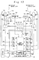
- the flight control computer 30 in the third embodiment includes an artificial feel unit 35 for generating a reaction force based on the flight condition of the fuselage 60.
- the flight control system in the third embodiment is provided with an artificial feel device 150 connected to either one of the link mechanisms 120A and 120B.
- the artificial feel device 150 is connected to the link mechanism 120B on the co-pilot control lever 10B side.
- the artificial feel unit 35 outputs an artificial feel device control signal Caf generated depending on the fuselage motion data and air data from the sensor 70, a preliminarily set artificial feel scheduling, and the like to control the artificial feel device 150.
- the artificial feel device 150 applies the reaction force based on the artificial feel device control signal Caf to the control lever 10 via the link mechanisms 120B and 120A.
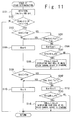
- FIG. 11 is a flowchart showing the stack determining operation at the step S1 in the third embodiment. Referring to FIG. 11 , details of the stack determining operation in the present embodiment will be explained. In the following description, the stack determining operation will be explained taking the stack determination to the roll input as an example, however, the stack determination to the pitch input is the same as that to the roll input and the explanation thereof is omitted.
- the stacking is determined on the basis of a force obtained by subtracting Faf, the reaction force of the artificial feel device, from a difference between the steering force Srm to the control lever 10 and the force Srk detected in the separation unit 100. That is, the stack determination processing in the third embodiment includes steps S301 and S302 in place of the steps S105 and S111 of the stack determination processing in the first embodiment.
- the stack determination portion 31 determines whether or not a value obtained by subtracting a value of the reaction force Faf from a value of a difference between the Srm and the Srk (the absolute value of (Srm-Srk)) is smaller than the Fsm (step S301).
- the stack determination portion 31 sets the Krm of a counter value to be 0 (Yes at the step S301, and then the step S104).
- the stack determination portion 31 adds 1 to the Krm of the counter value (No at the step S301, and then the step S106). In the same manner, in the processing at the step S109, when the absolute value of the Src is larger than the Fxc, the stack determination portion 31 determines whether a value obtained by subtracting a value of the reaction force Faf from a value of a difference between the Src and the Srk (the absolute value of "Src-Srk”) is smaller than the Fsc or not (step S302).
- the stack determination portion 31 sets the Krc of the counter value to be 0 (Yes at the step S302, and then the step S110).
- the stack determination portion 31 adds 1 to the Krc of the counter value (No at the step S302, and then the step S112).
- the flight system in the third embodiment can carry out the stack determination with considering the reaction force in the artificial feel device.
- the above mentioned stack determination method is effective for a case where a variable artificial feel device is provided.
- the stack determination is carried out on the basis of the Fsm and Fsc set with considering the reaction force in the method shown in the first embodiment.
- the flight control system in the fourth embodiment is configured by adding a stack confirming function to the flight control system in the first embodiment.
- Only components and operations different from those of the first embodiment will be explained, and the explanations of the same components and operations as those of the first embodiment are omitted.
- the flight control system in the fourth embodiment includes a confirmation switch (a confirmation SW) 160.
- the pilot confirms the stack determination result displayed on the display 130, and executes the separation of the link mechanism by operating the confirmation SW 160 when the stacking occurs. Even when detecting the stacking, the stack determination portion 31 in the fourth embodiment does not carry out the separation control of the link mechanism until a confirmation command Cc for ordering the separation is inputted from the confirmation SW 160.
- FIGS. 13A and 13B are flowcharts showing the stack determining operation at the step S1 in the fourth embodiment. Referring to FIGS. 13A and 13B , details of the stack determining operation in the present embodiment will be explained. In the following description, the stack determining operation will be explained taking the stack determination to the roll input as an example, however, the stack determination to the pitch input is the same as that to the roll input and the explanation thereof is omitted.
- the step S401 is included in place of the step S108 in the first embodiment and the step S402 is included in place of the step S114, and a confirmation processing (steps S403 to S405) based on the confirmation signal Cc is further added.
- the stack determination portion 31 sets XSTKrm to be 1 and resets the Krm (step S401).
- the XSTKrm is a stack determination flag before the confirmation of the roll input system on the main pilot side.
- the XSTKrm is set to be 0 as an initial value (non-stacked), and shows the stacking when set to be 1.
- the stacking determination portion 31 outputs information showing the occurrence of the stacking in the roll input system of the main pilot control lever 10A to the output unit 33 as the determination result J1.
- the display 130 displays to be visible that the roll input system of the main pilot control lever 10A is stacked.
- the stack determination portion 31 sets the XSTKrc to be 1 and resets the Krc (step S402).
- XSTKpm shows the stack determination flag before the confirmation of the pitch input system on the main pilot side
- XSTKrc shows the stack determination flag before the confirmation of the roll input system on the co-pilot side
- XSTKpc shows the stack determination flag before the confirmation of the pitch input system on the co-pilot side.
- the stacking determination portion 31 When the XSTKrm is set to be 1, the stacking determination portion 31 outputs information showing the occurrence of the stacking in the roll input system of the main pilot control lever 10A to the output unit 33 as the determination result J1. According to this, the display 130 displays to be visible that the roll input system of the main pilot control lever 10A is stacked.
- the stack determination portion 31 confirms a value set to parameter SWk (step S403).
- the SMk is a parameter whose value is set by the confirmation signal Cc.
- the SWk is set to "Confirmed” on the basis of the confirmation signal Cc showing the confirmation, the SWk is set to "Reset” on the basis of the confirmation signal Cc showing the reset, and the SWk is set to "Non-operated” on the basis of the confirmation signal Cc showing the non-operation.
- the stack determination portion 31 sets the XSTKrm, XSTKpm, XSTKrc, and XSTKpc to the STKrm, STKpm, STKrc, and STKpc, respectively (step S404). On this occasion, the stack determination portion 31 may output a signal for deleting the display indicating the stacking to the display 130 via the output unit 33.
- the stack determination portion 31 sets all of the XSTKrm, XSTKpm, STKrc, and XSTKpc to be 0 (step S405).
- the stack determination portion 31 may output the signals for deleting the display indicating the stacking to the display 130 via the output unit 33.
- the SWk is set to the "Non-operated" at the step S403
- the professing proceeds to next processing without any operation.
- the separation of the link mechanism between the control levers can be carried out after the stacking is confirmed by the pilot. For this reason, the separation at a timing not intended by the pilot can be avoided.
- the separation of the link mechanism is carried out on the basis of the pilot operation, the separation caused by an erroneous decision of the flight control computer 30 can be avoided.
- the flight control system in the fifth embodiment is configured by adding a determination ordering function to the flight control system in the first embodiment.
- a determination ordering function to the flight control system in the first embodiment.
- the flight control system in the fifth embodiment includes a determination switch (a determination SW) 170.
- a determination switch a determination SW 170.
- the pilot can order the flight control computer 30 to carry out the stack determination by operating the determination SW 170.
- the stack determination portion 31 in the fifth embodiment carries out the stack processing on the basis of a determination signal Cj from the determination SW 170.
- FIG. 15 is a flowchart showing the stack determining operation at the step S1 the fifth embodiment. Referring to FIG. 15 , details of the stack determining operation in the present embodiment will be explained. In the following description, the stack determining operation will be explained taking the stack determination to the roll input as an example, however, the stack determination to the pitch input is the same as that to the roll input and the explanation thereof is omitted.
- the confirmation processing of SWjdg is executed at predetermined timing before the step S101 in the first embodiment (step S501),
- the SWjdg is a determination ordering flag set to be “1 (Determine)" or “0 (Reset) " depending on the inputted determination signal Cj.
- the stack determination portion 31 sets the Krm and Krc to be 0 (step S502), and the processing proceeds to next processing (No at the step S501).
- the SWjdg is set to be the "Determine” at the step S501, the processing shifts to the step S101 and executes the stack determination processing in the same manner as the first embodiment (Yes at the step S501).
- the flight control system in the fifth embodiment since carrying out the stack determination on the basis of the operation of the confirmation SW 170 by the pilot, the flight control system in the fifth embodiment does not constantly execute the stack determination processing. Since the pilot can carry out a determination of malfunction only in a determination mode by operating the determination switch when the pilot determines that there is the possibility of the stacking, the separation at the timing not intended by the pilot can be avoided and also the separation caused by an erroneous stacking decision can be avoided. In addition, a processing load of the flight control computer can be reduced.
Landscapes
- Engineering & Computer Science (AREA)
- Automation & Control Theory (AREA)
- Aviation & Aerospace Engineering (AREA)
- Mechanical Control Devices (AREA)
Applications Claiming Priority (2)
| Application Number | Priority Date | Filing Date | Title |
|---|---|---|---|
| JP2008039342A JP4691121B2 (ja) | 2008-02-20 | 2008-02-20 | 操縦システム、操縦桿リンク切り離し方法 |
| PCT/JP2008/061533 WO2009104288A1 (fr) | 2008-02-20 | 2008-06-25 | Système de contrôle et procédé de séparation de l'articulation d'une barre de commande |
Publications (2)
| Publication Number | Publication Date |
|---|---|
| EP2184228A1 true EP2184228A1 (fr) | 2010-05-12 |
| EP2184228A4 EP2184228A4 (fr) | 2013-07-24 |
Family
ID=40985183
Family Applications (1)
| Application Number | Title | Priority Date | Filing Date |
|---|---|---|---|
| EP08790600.4A Withdrawn EP2184228A4 (fr) | 2008-02-20 | 2008-06-25 | Système de contrôle et procédé de séparation de l'articulation d'une barre de commande |
Country Status (6)
| Country | Link |
|---|---|
| US (1) | US8352098B2 (fr) |
| EP (1) | EP2184228A4 (fr) |
| JP (1) | JP4691121B2 (fr) |
| BR (1) | BRPI0815764B1 (fr) |
| CA (1) | CA2697432C (fr) |
| WO (1) | WO2009104288A1 (fr) |
Cited By (1)
| Publication number | Priority date | Publication date | Assignee | Title |
|---|---|---|---|---|
| CN104527970A (zh) * | 2014-12-04 | 2015-04-22 | 中国航空工业集团公司第六三一研究所 | 一种分布式大型飞机襟翼控制计算机系统 |
Families Citing this family (14)
| Publication number | Priority date | Publication date | Assignee | Title |
|---|---|---|---|---|
| JP4935875B2 (ja) * | 2009-09-04 | 2012-05-23 | 株式会社デンソー | 操作装置 |
| FR2952447B1 (fr) * | 2009-11-06 | 2012-08-17 | Ratier Figeac Soc | Dispositif de controle electronique de fonctionnement d'un organe de pilotage a surveillance croisee, dispositif de pilotage et aeronef |
| DE102010035822A1 (de) * | 2010-08-30 | 2012-03-01 | Liebherr-Aerospace Lindenberg Gmbh | Steuersystem für ein Luftfahrzeug |
| US9004411B2 (en) * | 2010-11-15 | 2015-04-14 | Michael Lam | Mechanical control mixer and method therefor |
| JP5819780B2 (ja) * | 2012-05-30 | 2015-11-24 | 住友精密工業株式会社 | 航空機操向装置の制御装置 |
| FR2993065B1 (fr) * | 2012-07-09 | 2014-08-29 | Ratier Figeac Soc | Dispositif de conjugaison d'effort entre organes de pilotage, organe de pilotage et aeronef |
| US9096325B2 (en) * | 2013-11-18 | 2015-08-04 | Bell Helicopter Textron Inc. | Fly-by-wire engine power control system |
| FR3031959B1 (fr) * | 2015-01-27 | 2017-02-17 | Ratier Figeac Soc | Procede et dispositif de conjugaison d'organes de pilotage |
| US11021244B2 (en) * | 2017-03-06 | 2021-06-01 | Textron Innovations Inc. | Collective control stick mounted throttle control assembly |
| US11014648B2 (en) | 2017-04-17 | 2021-05-25 | Textron Innovations, Inc. | Interconnected sidesticks for fly-by-wire flight control |
| US10793257B2 (en) * | 2018-02-05 | 2020-10-06 | The Boeing Company | Flight control systems and methods for an aerial vehicle |
| US11649040B2 (en) * | 2020-07-24 | 2023-05-16 | Tlie Boeing Company | Providing continuously variable feel forces for fully-powered flight control systems |
| TR2021018065A1 (tr) * | 2021-11-19 | 2023-06-21 | Tusas Tuerk Havacilik Ve Uzay Sanayii Anonim Sirketi | Bir kuvvet ölçüm sistemi. |
| US20240409202A1 (en) * | 2023-06-07 | 2024-12-12 | Textron Aviation Inc. | Fly by Wire Flight Control System |
Family Cites Families (12)
| Publication number | Priority date | Publication date | Assignee | Title |
|---|---|---|---|---|
| US3949958A (en) * | 1973-12-07 | 1976-04-13 | Lockheed Aircraft Corporation | Pitch control system |
| DE3638821A1 (de) * | 1986-09-12 | 1988-03-24 | Messerschmitt Boelkow Blohm | Hoehenruder-steuerungssystem |
| US5493497A (en) | 1992-06-03 | 1996-02-20 | The Boeing Company | Multiaxis redundant fly-by-wire primary flight control system |
| US5456428A (en) * | 1993-07-21 | 1995-10-10 | Honeywell Inc. | Mechanically linked active sidesticks |
| US5489830A (en) * | 1994-09-09 | 1996-02-06 | Mcdonnell Douglas Corporation | Control system with loadfeel and backdrive |
| US5797564A (en) * | 1995-05-15 | 1998-08-25 | The Boeing Company | System for backdrive of flight deck controls during autopilot operation |
| US5782436A (en) * | 1996-01-19 | 1998-07-21 | Mcdonnell Douglas Corporation | Torque tube breakout mechanism |
| JPH10127946A (ja) * | 1996-11-05 | 1998-05-19 | Konami Co Ltd | 操作レバー装置 |
| JP2000335496A (ja) * | 1999-05-31 | 2000-12-05 | Mitsubishi Heavy Ind Ltd | 航空機の操縦システム |
| GB0127254D0 (en) * | 2001-11-13 | 2002-01-02 | Lucas Industries Ltd | Aircraft flight surface control system |
| FR2899562B1 (fr) * | 2006-04-05 | 2009-01-09 | Eurocopter France | Dispositif de commandes de vol d'un giravion |
| JP4919271B2 (ja) | 2006-08-09 | 2012-04-18 | 株式会社パロマ | 調理器用温度センサ |
-
2008
- 2008-02-20 JP JP2008039342A patent/JP4691121B2/ja not_active Expired - Fee Related
- 2008-06-25 US US12/674,509 patent/US8352098B2/en not_active Expired - Fee Related
- 2008-06-25 CA CA2697432A patent/CA2697432C/fr not_active Expired - Fee Related
- 2008-06-25 EP EP08790600.4A patent/EP2184228A4/fr not_active Withdrawn
- 2008-06-25 BR BRPI0815764A patent/BRPI0815764B1/pt not_active IP Right Cessation
- 2008-06-25 WO PCT/JP2008/061533 patent/WO2009104288A1/fr not_active Ceased
Cited By (2)
| Publication number | Priority date | Publication date | Assignee | Title |
|---|---|---|---|---|
| CN104527970A (zh) * | 2014-12-04 | 2015-04-22 | 中国航空工业集团公司第六三一研究所 | 一种分布式大型飞机襟翼控制计算机系统 |
| CN104527970B (zh) * | 2014-12-04 | 2017-01-04 | 中国航空工业集团公司第六三一研究所 | 一种分布式大型飞机襟翼控制计算机系统 |
Also Published As
| Publication number | Publication date |
|---|---|
| EP2184228A4 (fr) | 2013-07-24 |
| WO2009104288A1 (fr) | 2009-08-27 |
| CA2697432C (fr) | 2014-01-07 |
| US8352098B2 (en) | 2013-01-08 |
| JP2009196475A (ja) | 2009-09-03 |
| BRPI0815764B1 (pt) | 2019-09-10 |
| JP4691121B2 (ja) | 2011-06-01 |
| BRPI0815764A2 (pt) | 2015-02-18 |
| US20100305780A1 (en) | 2010-12-02 |
| CA2697432A1 (fr) | 2009-08-27 |
Similar Documents
| Publication | Publication Date | Title |
|---|---|---|
| EP2184228A1 (fr) | Système de contrôle et procédé de séparation de l'articulation d'une barre de commande | |
| EP2620362B1 (fr) | Mode de système de commande de vol et procédé de fourniture de commande de vitesse de l'aéronef par l'utilisation de la commande marche-arrêt momentanée | |
| US20180334245A1 (en) | Method of controlling an artificial force feel generating device for generation of an artificial feeling of force on an inceptor of a vehicle control system | |
| KR101477275B1 (ko) | 주 조종 장치 | |
| US11117653B2 (en) | System and method for tactile cueing through rotorcraft pilot controls using variable friction and force gradient | |
| CA2642803C (fr) | Attribution d'effecteur de commande robuste | |
| EP3366574B1 (fr) | Repère tactile inverse pour la protection contre la survitesse d'un rotor de giravion | |
| EP3069990A1 (fr) | Dispositif de génération de sensation de force artificielle pour un système de commande d'un véhicule et, en particulier, d'un aéronef | |
| EP3729043B1 (fr) | Procédé et appareil d'affichage d'interface interactive pendant un événement anormal d'aéronef | |
| JP2009523657A (ja) | 統合バックアップ制御システム用のシステムおよび方法 | |
| EP3016857B1 (fr) | Organe de commande et procédé de fonctionnement | |
| EP3569497B1 (fr) | Système et procédé de repérage tactile grâce à des commandes pilotes de giravion utilisant un gradient de force et de friction variable | |
| EP3492373B1 (fr) | Système et procédé d'annonce de mode de vol | |
| EP3456626B1 (fr) | Dispositif de commande de pédale électrique pour aéronef | |
| US20110153176A1 (en) | Systems and methods for adaptive deceleration | |
| Schlautmann et al. | Run-Time Assurance Based Flight Control System Architecture for a Hybrid Fly-By-Wire Light Sport Aircraft | |
| EP4320043B1 (fr) | Commande d'automanette d'aéronef monté rétroactivement pour aéronef avec dispositifs de commande de moteur | |
| US20220219810A1 (en) | Systems and methods for protecting flight control systems | |
| EP3650336A1 (fr) | Système de commande de gouverne | |
| KR101885663B1 (ko) | 기계식 조종장치를 백업으로 갖는 전자식 비행제어 시스템 | |
| CN121084595A (zh) | 一种电传飞控操纵系统、方法及电动飞行器 |
Legal Events
| Date | Code | Title | Description |
|---|---|---|---|
| PUAI | Public reference made under article 153(3) epc to a published international application that has entered the european phase |
Free format text: ORIGINAL CODE: 0009012 |
|
| 17P | Request for examination filed |
Effective date: 20100223 |
|
| AK | Designated contracting states |
Kind code of ref document: A1 Designated state(s): AT BE BG CH CY CZ DE DK EE ES FI FR GB GR HR HU IE IS IT LI LT LU LV MC MT NL NO PL PT RO SE SI SK TR |
|
| AX | Request for extension of the european patent |
Extension state: AL BA MK RS |
|
| DAX | Request for extension of the european patent (deleted) | ||
| A4 | Supplementary search report drawn up and despatched |
Effective date: 20130620 |
|
| RIC1 | Information provided on ipc code assigned before grant |
Ipc: B64C 13/12 20060101AFI20130614BHEP Ipc: B64C 13/00 20060101ALI20130614BHEP |
|
| 17Q | First examination report despatched |
Effective date: 20171005 |
|
| GRAP | Despatch of communication of intention to grant a patent |
Free format text: ORIGINAL CODE: EPIDOSNIGR1 |
|
| INTG | Intention to grant announced |
Effective date: 20180613 |
|
| RAP1 | Party data changed (applicant data changed or rights of an application transferred) |
Owner name: MITSUBISHI HEAVY INDUSTRIES, LTD. |
|
| STAA | Information on the status of an ep patent application or granted ep patent |
Free format text: STATUS: THE APPLICATION IS DEEMED TO BE WITHDRAWN |
|
| 18D | Application deemed to be withdrawn |
Effective date: 20181024 |