EP2184436A2 - Bohrlochvorrichtung und -verfahren - Google Patents
Bohrlochvorrichtung und -verfahren Download PDFInfo
- Publication number
- EP2184436A2 EP2184436A2 EP09175592A EP09175592A EP2184436A2 EP 2184436 A2 EP2184436 A2 EP 2184436A2 EP 09175592 A EP09175592 A EP 09175592A EP 09175592 A EP09175592 A EP 09175592A EP 2184436 A2 EP2184436 A2 EP 2184436A2
- Authority
- EP
- European Patent Office
- Prior art keywords
- conduit
- flow path
- tubular body
- sand control
- control device
- Prior art date
- Legal status (The legal status is an assumption and is not a legal conclusion. Google has not performed a legal analysis and makes no representation as to the accuracy of the status listed.)
- Withdrawn
Links
- 238000000034 method Methods 0.000 title claims abstract description 26
- 239000012530 fluid Substances 0.000 claims abstract description 77
- 239000004576 sand Substances 0.000 claims abstract description 75
- 230000004888 barrier function Effects 0.000 claims abstract description 26
- 238000004891 communication Methods 0.000 claims abstract description 19
- 238000009434 installation Methods 0.000 claims abstract description 10
- 238000012856 packing Methods 0.000 claims abstract description 6
- 238000004519 manufacturing process Methods 0.000 claims description 26
- 230000015572 biosynthetic process Effects 0.000 claims description 13
- 239000013618 particulate matter Substances 0.000 claims description 7
- 238000011144 upstream manufacturing Methods 0.000 claims description 4
- 230000000694 effects Effects 0.000 abstract description 8
- 229920001971 elastomer Polymers 0.000 description 15
- 239000000806 elastomer Substances 0.000 description 10
- 230000006870 function Effects 0.000 description 9
- 238000002955 isolation Methods 0.000 description 9
- 239000000463 material Substances 0.000 description 9
- 230000008878 coupling Effects 0.000 description 8
- 238000010168 coupling process Methods 0.000 description 8
- 238000005859 coupling reaction Methods 0.000 description 8
- 238000007789 sealing Methods 0.000 description 5
- 239000004215 Carbon black (E152) Substances 0.000 description 4
- 230000008901 benefit Effects 0.000 description 4
- 230000008859 change Effects 0.000 description 4
- 230000003628 erosive effect Effects 0.000 description 4
- 229930195733 hydrocarbon Natural products 0.000 description 4
- 150000002430 hydrocarbons Chemical class 0.000 description 4
- 230000037361 pathway Effects 0.000 description 4
- 239000013536 elastomeric material Substances 0.000 description 3
- 239000002245 particle Substances 0.000 description 3
- 239000007787 solid Substances 0.000 description 3
- 230000008961 swelling Effects 0.000 description 3
- 229920002943 EPDM rubber Polymers 0.000 description 2
- 238000010276 construction Methods 0.000 description 2
- 238000006073 displacement reaction Methods 0.000 description 2
- 238000009826 distribution Methods 0.000 description 2
- 238000005553 drilling Methods 0.000 description 2
- 230000007246 mechanism Effects 0.000 description 2
- 230000009467 reduction Effects 0.000 description 2
- 229910000831 Steel Inorganic materials 0.000 description 1
- 238000005299 abrasion Methods 0.000 description 1
- 230000004913 activation Effects 0.000 description 1
- 239000012267 brine Substances 0.000 description 1
- 230000003247 decreasing effect Effects 0.000 description 1
- 230000007812 deficiency Effects 0.000 description 1
- -1 ethylene propylene diene Chemical class 0.000 description 1
- 238000001125 extrusion Methods 0.000 description 1
- 238000001914 filtration Methods 0.000 description 1
- 238000007667 floating Methods 0.000 description 1
- 230000003993 interaction Effects 0.000 description 1
- 230000007774 longterm Effects 0.000 description 1
- 239000002184 metal Substances 0.000 description 1
- 230000008569 process Effects 0.000 description 1
- 230000001681 protective effect Effects 0.000 description 1
- 239000002002 slurry Substances 0.000 description 1
- HPALAKNZSZLMCH-UHFFFAOYSA-M sodium;chloride;hydrate Chemical compound O.[Na+].[Cl-] HPALAKNZSZLMCH-UHFFFAOYSA-M 0.000 description 1
- 239000010959 steel Substances 0.000 description 1
- 238000003860 storage Methods 0.000 description 1
Images



Classifications
-
- E—FIXED CONSTRUCTIONS
- E21—EARTH OR ROCK DRILLING; MINING
- E21B—EARTH OR ROCK DRILLING; OBTAINING OIL, GAS, WATER, SOLUBLE OR MELTABLE MATERIALS OR A SLURRY OF MINERALS FROM WELLS
- E21B33/00—Sealing or packing boreholes or wells
- E21B33/10—Sealing or packing boreholes or wells in the borehole
- E21B33/12—Packers; Plugs
-
- E—FIXED CONSTRUCTIONS
- E21—EARTH OR ROCK DRILLING; MINING
- E21B—EARTH OR ROCK DRILLING; OBTAINING OIL, GAS, WATER, SOLUBLE OR MELTABLE MATERIALS OR A SLURRY OF MINERALS FROM WELLS
- E21B43/00—Methods or apparatus for obtaining oil, gas, water, soluble or meltable materials or a slurry of minerals from wells
- E21B43/02—Subsoil filtering
- E21B43/04—Gravelling of wells
-
- E—FIXED CONSTRUCTIONS
- E21—EARTH OR ROCK DRILLING; MINING
- E21B—EARTH OR ROCK DRILLING; OBTAINING OIL, GAS, WATER, SOLUBLE OR MELTABLE MATERIALS OR A SLURRY OF MINERALS FROM WELLS
- E21B33/00—Sealing or packing boreholes or wells
- E21B33/10—Sealing or packing boreholes or wells in the borehole
- E21B33/12—Packers; Plugs
- E21B33/1208—Packers; Plugs characterised by the construction of the sealing or packing means
-
- E—FIXED CONSTRUCTIONS
- E21—EARTH OR ROCK DRILLING; MINING
- E21B—EARTH OR ROCK DRILLING; OBTAINING OIL, GAS, WATER, SOLUBLE OR MELTABLE MATERIALS OR A SLURRY OF MINERALS FROM WELLS
- E21B33/00—Sealing or packing boreholes or wells
- E21B33/10—Sealing or packing boreholes or wells in the borehole
- E21B33/12—Packers; Plugs
- E21B33/124—Units with longitudinally-spaced plugs for isolating the intermediate space
Definitions
- the present invention relates to an apparatus and method for use in wellbores for the hydrocarbon exploration and production industry.
- the invention relates particularly, although not exclusively, to an apparatus and method for providing an alternate flow path in isolation devices.
- a wellbore packer provides a seal in the annular space between two tubing strings, or between an outer casing and an open hole.
- a packer may be run with a completion string to a downhole location, and may be inflated or expanded into contact with the outer casing or open hole.
- the packer may be designed to create a complete fluid seal capable of withholding a differential pressure on either side of the packer, thereby isolating one portion of the annulus from another.
- the packer may simply provide an annular barrier, to prevent or restrict flow of fluids and/or solid particles in the annulus.
- Packers may for example be run on completion strings, specialised mandrels, coiled tubing, wireline and slickline tools.
- packers are activated by mechanical or hydraulic systems. More recently, packers have been developed which include a mantle of swellable elastomeric material formed around a tubular body.
- the swellable elastomer is selected to increase in volume on exposure to a triggering fluid, which may be a hydrocarbon fluid or an aqueous fluid or brine. Alternatively, the elastomer may be selected to increase in volume on exposure to another triggering mechanism, such as heat or pressure.
- the packer is run to a downhole location in its unexpanded state, where it is exposed to a triggering fluid and caused to expand.
- Swellable packers have several advantages over conventional packers including passive actuation, simplicity of construction, and robustness in long term isolation applications. Examples of swellable packers and suitable materials are described in GB 2411918 .
- FIG. 1 An example of a multi-zone completion system is shown in Figure 1 .
- the system generally shown at 100, includes a production facility at surface, which in this case is a floating production storage and offloading (FPSO) vessel 102, coupled to a well 104 via subsea tree 106.
- the wellbore in this case is an inclined wellbore which extends through multiple production intervals 107a, 107b, 107c in the formation 108.
- the production tubing 110 provides a continuous flow path which penetrates through the multiple zones.
- the production tubing is provided with ports or inflow control devices (not shown) which allow production fluid to flow into the production tubing and out to the subsea tree 106.
- the annulus 112 is sealed by packers 114 between the different production zones 107 to prevent fluid flowing in the annulus between the different zones.
- the production tubing may be provided with sand control devices 116, to prevent solid particles from the formation entering the production tubing.
- the sand control devices 116 may for example be any suitable sand screen system, including expandable screen systems.
- the sand control devices may be used in conjunction with one or more gravel packs 118, which comprise gravel or other particulate matter around the sand control device to improve filtration and to provide additional support to the formation. Gravel packing requires a good distribution of gravel in the annulus at the sand control device.
- sand control devices have been provided with shunt tubes, which create alternate flow paths for the gravel and its carrier fluid. These alternate flow paths significantly improve the distribution of gravel in the production interval, for example by allowing the carrier fluid and gravel to be delivered through sand bridges that may be formed in the annulus before the gravel pack has been completed.
- FIGS 2A and 2B are schematic views of examples of sand screens provided with shunt tubes in a completion system 200.
- a first sand control device 202a is coupled to a second sand control device 202b, and each comprise base pipes 204 joined to define a production bore 206.
- Screens 208 including filter media surround the base pipe 204 and are supported by ribs 210.
- the apparatus is provided with shunt tubes 212, which in this example are steel tubes having substantially rectangular cross-section.
- the shunt tubes 212 are supported on the exterior of the screen and provide a flow path 213 alternate to the main production bore 206.
- Jumper tubes 211 are used to provide fluid communication between shunt tubes of adjacent sand control devices.
- the shunt tubes 212 maintain a flow path 213, even if the annular space 214 is bridged, for example by a loss of integrity in a part of the formation 216.
- Examples of shunt tube arrangements can be found in US 4945991 and US 5113935 .
- the shunt tubes may also be internal to the filter media, as described in US 5515915 and US 6227303 .
- WO 2007/092082 and WO 2007/092083 do not fully address the complexities of providing fluid barriers and/or fluid isolation using swellable elastomer systems.
- WO 2007/092082 and WO 2007/092083 are concerned with providing a continuous flow path, but do not address the problems of maintaining the required annular barrier or fluid seal functions of the packer with the provision of the secondary flow path through the apparatus. Such problems may arise due to removal of a volume of elastomer from the isolation device, improper sealing around the conduits, displacement of the conduits due to expansion of the element, and/or coupling of the conduits at opposing ends of the isolation device.
- WO 2007/092082 and WO 2007/092083 necessitate a reduction in the overall volume of the expanding element, and in particular a reduction in the volume of the expanding element which is radially outward of the conduit.
- An arrangement with individual jumper tubes requires the jumper tubes to be aligned with the shunt tubes of the adjacent sand control devices.
- WO 2007/092082 discloses an outer diameter of expanding element which is significantly below the outer diameter of adjacent sand control devices. This configuration would limit the swelling performance from a swellable mantle as it provides minimal mantle thickness. It is possible that at its fully swollen state it would not contact the internal diameter of the drilled wellbore.
- configuring a swellable elastomer well packer to achieve a seal at a fully swollen condition may mean extremely long or impractical sealing times and marginal pressure sealing performance if the swellable mantle did manage to contact the wellbore.
- the run-in diameter of the expanding element is increased beyond the diameter of the shunt tubes, and the swellable mantle is be the largest tool diametrically within a sand control string. This limits swelling performance and can impact on the success of deployment operations. It is desirable for the packer outer diameter to be small during run-in to avoid contact with obstructions, for example ledges or washout zones. When using swellable elastomer materials, they may begin to expand as they contact drilling or wellbore fluids during run-in to the desired position in the wellbore.
- an apparatus for use in a wellbore comprising: a tubular body having a longitudinal axis and a throughbore which defines a primary fluid path through the apparatus; an expanding element disposed around the tubular body and configured to provide an annular barrier in a space between the tubular body and a surrounding wall; and a conduit defining a secondary flow path through the apparatus and configured to be in fluid communication with at least one alternate path in an adjacent wellbore component, wherein the conduit is arranged to vary the secondary flow path along a longitudinal direction of the apparatus.
- the apparatus of the invention is configured for improved operation of the expanding element of the apparatus.
- the required annular barrier and/or sealing function of the expanding element can be maintained even with the provision of the secondary flow path through the apparatus.
- the conduit is configured to have a reduced effect on the operation of the expanding element, while still allowing the conduit to be coupled to alternate flow paths of adjacent apparatus.
- the apparatus may be a wellbore packer, configured to provide a seal in the space between the tubular body and the surrounding wall.
- the apparatus may alternatively be configured to provide an annular barrier which inhibits fluid flow in the space and/or prevents the movement of solid particles in the annulus.
- the at least one alternate path may be defined by at least one shunt tube.
- the adjacent wellbore component is preferably a sand control apparatus, such as a screen.
- the apparatus is preferably operable to be coupled to a first sand control device and a second sand control device.
- the conduit is preferably configured to be in fluid communication with a first shunt tube of a first of a first sand control device disposed in an uphole direction of the apparatus.
- the conduit may be in fluid communication with a second shunt tube of a second sand control device disposed in a downhole direction of the apparatus.
- the conduit is configured for the passage of a carrier fluid containing particulate matter for a gravel pack, and thus the apparatus may be used in a gravel pack operation.
- the gravel pack may be formed at least in part at the location of a sand control device disposed in a downhole direction of the apparatus.
- the gravel pack may be formed by passing the carrier fluid through a first shunt tube of a first sand control device disposed in an uphole direction of the apparatus, and through the conduit of the apparatus.
- the carrier fluid may be passed through a second shunt tube of a second sand control device disposed in a downhole direction of the apparatus.
- the conduit may be arranged to vary a radial dimension of the secondary flow path.
- the conduit may be arranged to vary the secondary flow path by changing the direction of fluid flowing in the secondary flow path.
- the conduit may be arranged to change the radial distance of the flow path from the longitudinal axis of the apparatus.
- the radial position of the flow path can be selected to improve the operation of the expanding element.
- Embodiments of the invention therefore have the advantage that the apparatus can be used with standard alternate flow path and shunt tube configurations adopted by various manufacturers of alternate paths and control systems.
- the conduit is configured to redirect the fluid flow radially inward of the apparatus.
- the conduit may comprise a first portion configured to redirect the flow, and may comprise a second portion arranged parallel to the longitudinal axis of the apparatus.
- the apparatus may comprise an s-bend in the secondary flow path.
- the first portion may be located in a gauge ring of the apparatus, or may be located in the expanding element. Alternatively, the first portion may be located in conduit extension members which are disposed outside of the expanding element and/or gauge ring.
- the conduit may comprise an inlet at a first radial distance from the longitudinal axis of the apparatus, and a second portion disposed at a second radial distance from the longitudinal axis of the apparatus, the second radial distance being less than the first radial distance.
- the conduit may be arranged to vary the secondary flow path by changing the cross-sectional profile of the conduit along the longitudinal direction of the apparatus. This may for example allow the conduit or a portion of it to be repositioned within the apparatus in order to have a minimal impact on the operation of the expanding element. It may also allow the flow area to be redistributed about the circumference of the apparatus to reduce the radial dimension of the flow path.
- the cross-sectional profile of the secondary flow path may be varied such that the total cross-sectional area of the conduit is substantially the same along the longitudinal direction of the apparatus. Thus the rate of flow of fluid through the conduit is substantially unaffected.
- the cross-sectional shape of the secondary flow path may be varied to change the total cross-sectional area of the secondary flow path longitudinally along the apparatus.
- the apparatus may comprise a conduit bore formed in the tubular body, which may be formed longitudinally in the wall of the tubular body.
- a plurality of conduit bores may be provided.
- the conduit bores may be in fluid communication with an alternate flow path via a manifold, and/or via a flow path in a gauge ring.
- the apparatus may comprise one or more conduits integrally formed with the tubular body.
- the apparatus may comprise one or more conduits unitarily formed with the tubular body.
- the conduit may comprise a support element such as a tubular conduit member, or may alternatively be defined by a recess or channel in the expanding element.
- a flexible or collapsible conduit member may be provided.
- the apparatus may comprise a gauge ring which is configured to be radially disposed onto the tubular body, for example by clamping.
- the gauge ring may comprise a formation such as a recessed channel shaped to receive a conduit.
- the formation may be configured to deform, bend, or otherwise reshape the conduit.
- the formation may comprise a wedge-shaped longitudinal profile.
- the wellbore installation comprises a second sand control device coupled to the apparatus upstream of the apparatus, and the apparatus provides a secondary flow path for a gravel pack between the second and first sand control devices.
- the wellbore installation may comprise a gravel pack disposed at one or both of the sand control devices.
- a method of forming a wellbore installation comprising:
- Varying the secondary flow path may comprise redirecting and/or redistributing the flow. It may comprise changing a radial dimension and/or position of the flow.
- the method may comprise forming a gravel pack by passing the carrier fluid through a first shunt tube of a first sand control device disposed in an uphole direction of the apparatus, and through the conduit of the apparatus.
- the method may comprise redirecting the secondary flow path to be radially closer to the longitudinal axis of the apparatus than the shunt tube.
- the method may comprise passing the carrier fluid through a second shunt tube of a second sand control device disposed in a downhole direction of the apparatus.
- an apparatus for use in a wellbore comprising: a tubular body having a longitudinal axis and a throughbore which defines a primary fluid path through the apparatus; an expanding element disposed around the tubular body and configured to provide an annular barrier in a space between the tubular body and a surrounding wall; and a conduit defining a secondary flow path through the apparatus and configured to be in fluid communication with at least one alternate path in an adjacent wellbore component at a first radial distance from the longitudinal axis of the tubular body, wherein at least a portion of the conduit is located at a second radial distance from the longitudinal axis of the tubular body, the second radial distance being less than the first radial distance.
- a method of forming a wellbore installation comprising:
- an assembly for use in a wellbore comprising: an apparatus having a tubular body with a first throughbore and an expanding element disposed around the tubular body and configured to provide an annular barrier in a space between the tubular body and a surrounding wall; and at least sand control device comprising a second throughbore and at least one shunt tube, the at least one sand control device coupled to the apparatus to define a primary flow path through the assembly via the first and second throughbores; wherein the assembly defines a secondary flow path for a gravel pack carrier fluid via the at least one shunt tube and through the apparatus, and wherein at least a portion of the secondary flow path is located radially closer to the primary flow path than the shunt tube.
- a method of forming a wellbore installation comprising:
- Embodiments of the various aspects of the invention may comprise preferred and optional features of other aspects of the invention.
- embodiments of the fifth and seventh aspects of the invention may comprise features of the first aspect.
- Embodiments of the invention may have particular application in the methods of operation described in WO 2007/092082 and WO 2007/092083 .
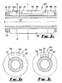
- FIG. 3A is a longitudinal section through the apparatus 300
- Figures 3B and 3C are respectively cross-sectional views through lines B-B' and C-C'.
- the packer 300 comprises a tubular body 302 which has a longitudinal axis A and a throughbore 304.
- the tubular body 302 is provided with couplings (not shown at each end), configured for connection in the production string.
- the couplings are suitable for connecting the packer to adjacent screen devices.
- the throughbore 304 defines a primary flow path for the passage of production fluids through the apparatus 300.
- gauge rings 306a, 306b Disposed at either end of the apparatus 300 are gauge rings 306a, 306b, which provide anti-extrusion resistance for the expanding element 308 and may also protect the expanding element from abrasion or contact with the wellbore during deployment operations.
- the gauge rings also function to secure the expanding element 308 in position on the tubular body 302, preventing axial displacement if the element does contact the wellbore.
- the gauge rings 306a, 306b are secured to the tubular body, for example by bolts or corresponding threads which are suitably aligned for a concentric packer design in this embodiment, but which may be aligned for eccentric or offset packer designs in other embodiments.
- the expanding element 308 is a swellable mantle, formed from a swellable elastomeric material selected to increase in volume on exposure to a triggering fluid.
- the material is an ethylene propylene diene M-class (EPDM) rubber, which increases in volume on exposure to a hydrocarbon fluid.
- EPDM ethylene propylene diene M-class
- Other suitable materials for the swellable mantle are known in the art, and include elastomers selected to increase in volume on exposure to aqueous fluids or brines, and materials selected to increase in volume on exposure to both aqueous and hydrocarbon fluids. Materials which increase in volume on exposure to other types of stimuli, such as heat and pressure are known in the art, and may be used to form the expanding element in other embodiments.
- the apparatus is provided with conduits 310a, 310b which extend through the apparatus to define a secondary flow path.
- Each conduit is of sufficient diameter to allow the through-flow of a carrier fluid and a particulate matter used to form a gravel pack.
- the conduits each comprise a metal tube which extends through the expanding element, and which functions to maintain the flow path through the expanding element.
- Each conduit includes an inlet 312 and an outlet 314 at opposing ends of the packer.
- the inlet 312 is configured to be coupled to a shunt tube (not shown) of an alternate path screen located at an uphole position of the packer 300.
- the outlet 314 is configured for coupling to a shunt tube of a screen located in a downhole position of the packer.
- the apparatus also includes an end ring 322 which is configured to support a shunt tube or the conduit members.
- the end ring may be an end ring of an adjacent sand control system.
- Each conduit extends through the gauge rings 306a, 306b and through the expanding element.
- the conduit varies the secondary flow path by redirecting the flow path from a first radial position, aligned with the shunt tube, to a second radial position disposed towards the tubular body. In this example, this is achieved by providing a first bended or curved portion 316 of the conduit between the inlet 312 and a central portion 318 of the conduit. Similarly, a second bent or curved portion 320 of the conduit is located between the central portion 318 and the outlet 314. This arrangement allows the central portion of the conduit to be located closer to the tubular body within the expanding element, which increases the volume of the expanding element radially outward of the central portion of the conduit. This improves the operation of the expanding element; by providing a greater volume of the swellable elastomer material outwardly of the conduit, a more effective and more rapid seal can be achieved.
- conduits 310a, 310b comprise an s-bend portion which changes the radial position of the secondary flow path within the apparatus. It will be appreciated that other shapes and dimensions of conduit may be provided in alternative embodiments of the invention. It will also be appreciated that any number of conduits may be provided within the scope of the invention.
- the apparatus 300 may be manufactured as follows.
- a base layer of EPDM rubber is formed on the tubular body.
- a conduit member 310 is located on the base layer of rubber in the required circumferential position, and successive layers of rubber may be formed around the conduit to build up the expanding element and embed it into the packer.
- the gauge rings may conveniently be of a clamp-on type, for example formed from part-cylindrical components secured together to form an annular ring. Thus the gauge rings may be placed over the conduit member in the required position. Alternatively, the end rings may be slipped on to the tubular body over the conduit members.
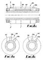
- Figures 4A to 4C An alternative embodiment of the apparatus is shown in Figures 4A to 4C .
- the wellbore packer generally shown at 340, is similar to the apparatus 300, and will be understood from Figures 3A to 3C .
- Figure 4A is a longitudinal section through the packer 340
- Figures 4B and 4C are respectively cross-sectional views through lines B-B' and C-C'.
- the packer 340 comprises a tubular body 342, a pair of gauge rings 346a, 346B, and an expanding element 348.
- Figure 4B is a section through the gauge ring 346a.
- the apparatus comprises a pair of conduits 350a, 350b configured to be in fluid communication with shunt tubes of adjacent sand control devices, in the manner described with reference to Figures 3A to 3C .
- the secondary flow path defined by the conduits 350 is varied by redirection of fluid flow.
- the packer 340 is similar in function to the packer 300, but differs in that the redirection of the flow takes place in portions of the conduit 356, 360 located in the gauge rings 346a, 346B.
- the central portion 358 of the conduit which extends through the expanding element 348 is parallel to the longitudinal axis A of the apparatus.
- the apparatus has a sufficient volume of swellable elastomeric material located radially outward of the conduit.
- FIGS. 6A to 6C show an apparatus 400 in accordance with a further alternative embodiment of the invention.
- the apparatus 400 comprises a tubular body 402, a pair of gauge rings 406a, 406b, and expanding element 408.
- Conduits 410 extend through the apparatus, and comprise a manifold portion 412 and tubular conduit members 414.
- the manifold portions 412 are formed as annular chambers in the gauge rings 406, and comprise an inlet in fluid communication with a shunt tube of an adjacent screen.
- the manifold portions 412 are provided with support members 415 which improve the strength of the gauge ring.
- the tubular conduit members extend between the respective manifold portions 412 through the expanding element 408.
- tubular conduit members 414c and 414d may be disposed further towards the tubular body, as is the case with tubular conduit members 414c and 414d. This increases the volume of the expanding element located radially outward of the conduit to a greater extent than is possible with the embodiments of Figures 3 to 5 .
- the cross-sectional shapes of the tubular conduit members of the conduit may also be used with the s-bend configurations shown in Figures 3 to 5 (or indeed other flow-redirecting configurations).
- the conduit may comprise a transitional portion (which may include a nozzle portion and/or a flared portion) which alters the shape of the conduit.
- the arrangement of Figure 6 also redistributes the flow from two shunt tubes of the screen system to four tubular conduit members 414 in the apparatus. This allows the respective flow areas of the tubular conduit members 414 to be reduced, allowing repositioning within the expanding element to a position which reduces the effect of performance on the function of the expanding element.
- the manifold portion 412 is an annular chamber extending around the tubular body.
- the manifold portion may only be on a circumferential part of the tubular body, and may not extend around its entire circumference.
- the manifold portion may be provided around sufficient circumferential distance to be in fluid communication with the openings to the tubular conduit members.
- inventions have an expanding element and corresponding gauge rings which are concentric with respect to the tubular body.
- the expanding element and gauge rings may be eccentric on the tubular body, in order to provide a greater available radial depth conduits can be accommodated.
- many alternate path sand control systems are eccentrically formed on the base pipe to accommodate shunt tubes on one side of the apparatus, and the apparatus of embodiments of the invention may be similarly arranged to allow it to be conveniently used with such systems.
- An exemplary arrangement is shown in cross section in Figure 7 .
- Packer 440 comprises a tubular body 442 and an expanding element 448 eccentrically located on the body.
- Conduits 450a, 450b define a secondary flow path through the expanding element, as will be understood from the previous embodiments.
- the conduits are located on one side of the apparatus to correspond with the location of the shunt tubes of the adjacent sand control devices.
- the conduits 450 are shaped to increase their circumferential dimension and reduce the radial dimension, relative to the dimensions of the corresponding shunt tubes.
- the conduits are also positioned radially inwardly of the shunt tubes, towards the tubular body, to increase the external volume of expanding element.
- Figure 8 is a cross-sectional view through an apparatus 460 in accordance with a further alternative embodiment.
- the apparatus comprises a tubular body 462 surrounded by an expanding element 464.
- the figure is a cross-section through a central portion of the packer 460.
- Conduits through the packer 460 are provided by tubular conduit members 466a, 466b, which are in a fluid communication with shunt tubes via a suitable manifold provided at end of the packer 460.
- the tubular conduit members 466a, 466b are similar to the tubular conduit members 414c, 414d of Figure 6C .
- the cross-section has been radially flattened (with respect to the cross-sections of corresponding shunt tubes) to redistribute the flow in a circumferential direction of the apparatus.
- the apparatus of Figure 8 differs from the apparatus of Figure 6C in that the tubular conduit members 466a, 466b are placed on the tubular body 462, and welded on to the body to create a seal.
- the tubular conduit members 466a, 466b are thus integrally formed with the tubular body in order to maximise the volume of the expanding rubber which is located radially outward of the tubular conduit members on the tool.
- the tubular body is shown concentric with the expanding element, although in other embodiments it may be eccentrically formed with the tubular conduit members located in the high radius side of the expanding element 464.
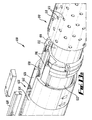
- Figures 10A to 10C are sectional views through an apparatus in accordance with further alternative embodiments.
- the apparatus is in the form of a packer 500, which comprises a tubular body 502, a pair of gauge rings 506 (one is shown in Figure 10A ) and an expanding element 508.
- Figure 10A is a longitudinal section through one end of the packer 500
- Figure 10B is a cross-section through line B-B'
- Figure 10C is a cross-section through lines C-C'.
- inserts may be provided in the apparatus to resist erosion due to redirection of the carrier fluid and gravel pack through the manifold and into the tubular conduits.
- the apertures 514 may be shaped or angled in the direction of fluid flow to reduce flow resistance and corresponding erosion issues (and similar features may also be provided in other embodiments of the invention described herein).
- the apparatus 520 is provided with a similar gauge ring at its opposing end (not shown).
- the gauge ring 526 comprises a shoulder portion 536 which abuts the end of the tubular body 522.
- the open ends of the conduit bores 524 are aligned with a flow path 538 in the special gauge ring which provides fluid communication to a shunt tube (not shown).
- the gauge ring 526, or portions of it, may be hardened to resist erosion.
- One advantage of this embodiment is that redirection of the flow takes place in the special gauge ring 526, and the tubular body 522 is unlikely to be subject to erosion issues.
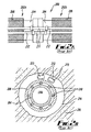
- FIGS 12A and 12B show a further alternative embodiment.
- the apparatus 540 comprises a tubular body 542 and an expanding element 548, formed from a swellable elastomer or rubber.
- the apparatus is shown in cross-section through a central portion of the apparatus. Opposing ends of the apparatus are provided with gauge rings and manifolds (not shown) which allow fluid communication between shunt tubes and conduits 544 of the apparatus.
- a secondary flow path is formed through the apparatus 540 through conduits 544 formed in the expanding element 548.
- Figure 12A shows the apparatus in a configuration where the conduits 544 are not active.
Landscapes
- Life Sciences & Earth Sciences (AREA)
- Engineering & Computer Science (AREA)
- Geology (AREA)
- Mining & Mineral Resources (AREA)
- Physics & Mathematics (AREA)
- Environmental & Geological Engineering (AREA)
- Fluid Mechanics (AREA)
- General Life Sciences & Earth Sciences (AREA)
- Geochemistry & Mineralogy (AREA)
- Pipe Accessories (AREA)
- Consolidation Of Soil By Introduction Of Solidifying Substances Into Soil (AREA)
Applications Claiming Priority (1)
| Application Number | Priority Date | Filing Date | Title |
|---|---|---|---|
| GB0820619.5A GB2466475B (en) | 2008-11-11 | 2008-11-11 | Wellbore apparatus and method |
Publications (2)
| Publication Number | Publication Date |
|---|---|
| EP2184436A2 true EP2184436A2 (de) | 2010-05-12 |
| EP2184436A3 EP2184436A3 (de) | 2017-04-12 |
Family
ID=40139732
Family Applications (1)
| Application Number | Title | Priority Date | Filing Date |
|---|---|---|---|
| EP09175592.6A Withdrawn EP2184436A3 (de) | 2008-11-11 | 2009-11-10 | Bohrlochvorrichtung und -verfahren |
Country Status (5)
| Country | Link |
|---|---|
| US (2) | US8403046B2 (de) |
| EP (1) | EP2184436A3 (de) |
| BR (1) | BRPI0904664A2 (de) |
| CA (1) | CA2685235C (de) |
| GB (2) | GB2488290B (de) |
Cited By (12)
| Publication number | Priority date | Publication date | Assignee | Title |
|---|---|---|---|---|
| WO2012084889A1 (en) | 2010-12-22 | 2012-06-28 | Shell Internationale Research Maatschappij B.V. | Method of providing an annular seal, and wellbore system |
| EP2597251A1 (de) * | 2011-11-22 | 2013-05-29 | Weatherford/Lamb Inc. | Eingangsschlauchsystem |
| WO2013184138A1 (en) | 2012-06-08 | 2013-12-12 | Halliburton Energy Services, Inc. | Shunt tube assembly entry device |
| WO2013187878A1 (en) | 2012-06-11 | 2013-12-19 | Halliburton Energy Services, Inc. | Shunt tube connection assembly and method |
| EP2665888A4 (de) * | 2010-12-17 | 2017-11-01 | Exxonmobil Upstream Research Company | Bohrlochvorrichtung und -verfahren für mehrzonenbohrlochabschluss, produktion und einspritzung |
| EP2652244A4 (de) * | 2010-12-17 | 2017-12-20 | Exxonmobil Upstream Research Company | Packer für wechselstromkanalkiesfüllung und verfahren zum abschluss eines bohrloches |
| EP3266977A1 (de) * | 2016-07-07 | 2018-01-10 | Welltec A/S | Ringförmige absperrung mit shuntrohr |
| GB2553823A (en) * | 2016-09-15 | 2018-03-21 | Weatherford Uk Ltd | Apparatus and methods for use in wellbore packing |
| GB2587283A (en) * | 2016-09-15 | 2021-03-24 | Weatherford Uk Ltd | Apparatus and methods for use in wellbore packing |
| GB2603587A (en) * | 2020-11-19 | 2022-08-10 | Schlumberger Technology Bv | Multi-zone sand screen with alternate path functionality |
| US12078036B2 (en) | 2020-04-08 | 2024-09-03 | Schlumberger Technology Corporation | Single trip wellbore completion system |
| US12134959B2 (en) | 2020-04-15 | 2024-11-05 | Schlumberger Technology Corporation | Multi-trip wellbore completion system with a service string |
Families Citing this family (47)
| Publication number | Priority date | Publication date | Assignee | Title |
|---|---|---|---|---|
| US7938184B2 (en) * | 2006-11-15 | 2011-05-10 | Exxonmobil Upstream Research Company | Wellbore method and apparatus for completion, production and injection |
| WO2008060297A2 (en) * | 2006-11-15 | 2008-05-22 | Halliburton Energy Services, Inc. | Well tool including swellable material and integrated fluid for initiating swelling |
| AU2007346700B2 (en) | 2007-02-06 | 2013-10-31 | Halliburton Energy Services, Inc. | Swellable packer with enhanced sealing capability |
| GB2488290B (en) * | 2008-11-11 | 2013-04-17 | Swelltec Ltd | Wellbore apparatus and method |
| US8047298B2 (en) | 2009-03-24 | 2011-11-01 | Halliburton Energy Services, Inc. | Well tools utilizing swellable materials activated on demand |
| BRPI1013547A2 (pt) | 2009-04-14 | 2016-04-12 | Exxonmobil Upstream Res Co | conjunto tubular adaptado para uso furo abaixo em poços, e, método para operar um poço relacionado a hidrocarboneto |
| EA023036B1 (ru) | 2009-11-20 | 2016-04-29 | Эксонмобил Апстрим Рисерч Компани | Пакер для установки гравийного фильтра по альтернативному пути и способ заканчивания ствола скважины с необсаженным забоем |
| US9464500B2 (en) | 2010-08-27 | 2016-10-11 | Halliburton Energy Services, Inc. | Rapid swelling and un-swelling materials in well tools |
| WO2012082447A1 (en) * | 2010-12-17 | 2012-06-21 | Exxonmobil Upstream Research Company | Wellbore apparatus and methods for zonal isolation and flow control |
| SG190865A1 (en) * | 2010-12-17 | 2013-07-31 | Exxonmobil Upstream Res Co | Crossover joint for connecting eccentric flow paths to concentric flow paths |
| US8783348B2 (en) * | 2010-12-29 | 2014-07-22 | Baker Hughes Incorporated | Secondary flow path module, gravel packing system including the same, and method of assembly thereof |
| US9157300B2 (en) | 2011-01-19 | 2015-10-13 | Baker Hughes Incorporated | System and method for controlling formation fluid particulates |
| US9587459B2 (en) | 2011-12-23 | 2017-03-07 | Weatherford Technology Holdings, Llc | Downhole isolation methods and apparatus therefor |
| US9010417B2 (en) * | 2012-02-09 | 2015-04-21 | Baker Hughes Incorporated | Downhole screen with exterior bypass tubes and fluid interconnections at tubular joints therefore |
| US8789611B2 (en) | 2012-02-29 | 2014-07-29 | Halliburton Energy Services, Inc. | Rotating and translating shunt tube assembly |
| US8794324B2 (en) * | 2012-04-23 | 2014-08-05 | Baker Hughes Incorporated | One trip treatment system with zonal isolation |
| WO2013162545A1 (en) * | 2012-04-25 | 2013-10-31 | Halliburton Energy Services, Inc. | Sand control device cleaning system |
| IN2014DN10330A (de) * | 2012-06-11 | 2015-08-07 | Halliburton Energy Services Inc | |
| GB2571028B (en) * | 2012-10-18 | 2019-11-06 | Halliburton Energy Services Inc | Gravel packing apparatus having a jumper tube protection assembly |
| EA030002B1 (ru) | 2012-10-26 | 2018-06-29 | Эксонмобил Апстрим Рисерч Компани | Скважинное устройство и способ борьбы с поступлением песка в скважину с применением гравийного резерва |
| US10012032B2 (en) | 2012-10-26 | 2018-07-03 | Exxonmobil Upstream Research Company | Downhole flow control, joint assembly and method |
| US10138707B2 (en) | 2012-11-13 | 2018-11-27 | Exxonmobil Upstream Research Company | Method for remediating a screen-out during well completion |
| AU2012397810B2 (en) | 2012-12-31 | 2016-12-15 | Halliburton Energy Services, Inc. | Distributed inflow control device |
| US8931568B2 (en) | 2013-03-14 | 2015-01-13 | Weatherford/Lamb, Inc. | Shunt tube connections for wellscreen assembly |
| CA2898463C (en) * | 2013-03-26 | 2017-10-03 | Halliburton Energy Services, Inc. | Annular flow control devices and methods of use |
| US9580999B2 (en) | 2013-05-20 | 2017-02-28 | Halliburton Energy Services, Inc. | Gravel packing apparatus having a jumper tube protection assembly |
| US9617836B2 (en) | 2013-08-23 | 2017-04-11 | Baker Hughes Incorporated | Passive in-flow control devices and methods for using same |
| US9428997B2 (en) | 2013-09-10 | 2016-08-30 | Weatherford/Lamb, Inc. | Multi-zone bypass packer assembly for gravel packing boreholes |
| US9816361B2 (en) | 2013-09-16 | 2017-11-14 | Exxonmobil Upstream Research Company | Downhole sand control assembly with flow control, and method for completing a wellbore |
| GB201400975D0 (en) | 2014-01-21 | 2014-03-05 | Swellfix Bv | Downhole packer and associated methods |
| MY180117A (en) | 2014-01-22 | 2020-11-23 | Weatherford Tech Holdings Llc | Leak-off assembly for gravel pack system |
| US9670756B2 (en) | 2014-04-08 | 2017-06-06 | Exxonmobil Upstream Research Company | Wellbore apparatus and method for sand control using gravel reserve |
| GB2543666B (en) * | 2014-04-21 | 2020-11-04 | Baker Hughes Inc | Tubular flow control apparatus and method of packing particulates using a slurry |
| US9856720B2 (en) | 2014-08-21 | 2018-01-02 | Exxonmobil Upstream Research Company | Bidirectional flow control device for facilitating stimulation treatments in a subterranean formation |
| US9951596B2 (en) | 2014-10-16 | 2018-04-24 | Exxonmobil Uptream Research Company | Sliding sleeve for stimulating a horizontal wellbore, and method for completing a wellbore |
| US10024143B2 (en) | 2015-06-11 | 2018-07-17 | Weatherford Technology Holdings, Llc | Jumper tube connection for wellscreen assembly |
| AU2016296605B2 (en) | 2015-07-22 | 2019-03-14 | Weatherford Technology Holdings, LLC. | Leak-off assembly for gravel pack system |
| US10422203B2 (en) * | 2017-03-22 | 2019-09-24 | Baker Hughes, A Ge Company, Llc | Screen connection area assembly for gravel pack and method |
| CA3059360C (en) | 2017-04-12 | 2023-07-25 | Weatherford Technology Holdings, Llc | Shunt tube connection assembly |
| EP3610126B1 (de) | 2017-04-12 | 2025-03-12 | Weatherford Technology Holdings, LLC | Blechanordnung |
| BR112019026851B1 (pt) * | 2017-07-21 | 2023-03-28 | Halliburton Energy Services Inc | Packer, e, sistema e método para fornecer fluxo de fluido para um furo de poço |
| US10724350B2 (en) | 2017-11-22 | 2020-07-28 | Exxonmobil Upstream Research Company | Perforation devices including trajectory-altering structures and methods of utilizing the same |
| US10662745B2 (en) | 2017-11-22 | 2020-05-26 | Exxonmobil Upstream Research Company | Perforation devices including gas supply structures and methods of utilizing the same |
| GB2575136B (en) * | 2018-01-29 | 2021-01-20 | Schlumberger Technology Bv | System and methodology for high pressure alternate path |
| WO2019165392A1 (en) * | 2018-02-26 | 2019-08-29 | Schlumberger Technology Corporation | Alternate path manifold life extension for extended reach applications |
| MY201345A (en) * | 2018-03-19 | 2024-02-18 | Halliburton Energy Services Inc | Systems and methods for gravel packing wells |
| US12006800B2 (en) * | 2020-04-21 | 2024-06-11 | Weatherford Technology Holdings, Llc | Screen assembly having permeable handling area |
Citations (6)
| Publication number | Priority date | Publication date | Assignee | Title |
|---|---|---|---|---|
| US4945991A (en) | 1989-08-23 | 1990-08-07 | Mobile Oil Corporation | Method for gravel packing wells |
| US5113935A (en) | 1991-05-01 | 1992-05-19 | Mobil Oil Corporation | Gravel packing of wells |
| US5515915A (en) | 1995-04-10 | 1996-05-14 | Mobil Oil Corporation | Well screen having internal shunt tubes |
| US6227303B1 (en) | 1999-04-13 | 2001-05-08 | Mobil Oil Corporation | Well screen having an internal alternate flowpath |
| GB2411918A (en) | 2004-03-12 | 2005-09-14 | Schlumberger Holdings | Sealing system |
| WO2007092083A2 (en) | 2006-02-03 | 2007-08-16 | Exxonmobil Upstream Research Company | Wellbore method and apparatus for completion, production and injection |
Family Cites Families (17)
| Publication number | Priority date | Publication date | Assignee | Title |
|---|---|---|---|---|
| US4258787A (en) * | 1979-07-11 | 1981-03-31 | Baker International Corporation | Subterranean well injection apparatus |
| US5332038A (en) * | 1992-08-06 | 1994-07-26 | Baker Hughes Incorporated | Gravel packing system |
| US5337808A (en) * | 1992-11-20 | 1994-08-16 | Natural Reserves Group, Inc. | Technique and apparatus for selective multi-zone vertical and/or horizontal completions |
| US5390966A (en) * | 1993-10-22 | 1995-02-21 | Mobil Oil Corporation | Single connector for shunt conduits on well tool |
| US6157893A (en) * | 1995-03-31 | 2000-12-05 | Baker Hughes Incorporated | Modified formation testing apparatus and method |
| US5588487A (en) * | 1995-09-12 | 1996-12-31 | Mobil Oil Corporation | Tool for blocking axial flow in gravel-packed well annulus |
| US6298916B1 (en) * | 1999-12-17 | 2001-10-09 | Schlumberger Technology Corporation | Method and apparatus for controlling fluid flow in conduits |
| US6439312B1 (en) * | 2000-08-11 | 2002-08-27 | Halliburton Energy Services, Inc. | Apparatus and methods for isolating a wellbore junction |
| US6588506B2 (en) * | 2001-05-25 | 2003-07-08 | Exxonmobil Corporation | Method and apparatus for gravel packing a well |
| US6516881B2 (en) * | 2001-06-27 | 2003-02-11 | Halliburton Energy Services, Inc. | Apparatus and method for gravel packing an interval of a wellbore |
| GB2413139B (en) * | 2002-12-26 | 2006-01-18 | Baker Hughes Inc | Alternative packer setting method |
| GB0411749D0 (en) * | 2004-05-26 | 2004-06-30 | Specialised Petroleum Serv Ltd | Downhole tool |
| BRPI0515491B1 (pt) * | 2004-09-20 | 2017-04-18 | Bj Services Co | válvula de segurança, obstruidor de fundo de poço e processo para instalar uma válvula de segurança |
| US7407007B2 (en) * | 2005-08-26 | 2008-08-05 | Schlumberger Technology Corporation | System and method for isolating flow in a shunt tube |
| US7562709B2 (en) * | 2006-09-19 | 2009-07-21 | Schlumberger Technology Corporation | Gravel pack apparatus that includes a swellable element |
| US7784532B2 (en) * | 2008-10-22 | 2010-08-31 | Halliburton Energy Services, Inc. | Shunt tube flowpaths extending through swellable packers |
| GB2488290B (en) * | 2008-11-11 | 2013-04-17 | Swelltec Ltd | Wellbore apparatus and method |
-
2008
- 2008-11-11 GB GB1210007.9A patent/GB2488290B/en active Active
- 2008-11-11 GB GB0820619.5A patent/GB2466475B/en active Active
-
2009
- 2009-11-09 CA CA2685235A patent/CA2685235C/en active Active
- 2009-11-10 EP EP09175592.6A patent/EP2184436A3/de not_active Withdrawn
- 2009-11-10 US US12/615,460 patent/US8403046B2/en active Active
- 2009-11-11 BR BRPI0904664-0A patent/BRPI0904664A2/pt not_active Application Discontinuation
-
2013
- 2013-03-21 US US13/848,552 patent/US8590617B2/en active Active
Patent Citations (7)
| Publication number | Priority date | Publication date | Assignee | Title |
|---|---|---|---|---|
| US4945991A (en) | 1989-08-23 | 1990-08-07 | Mobile Oil Corporation | Method for gravel packing wells |
| US5113935A (en) | 1991-05-01 | 1992-05-19 | Mobil Oil Corporation | Gravel packing of wells |
| US5515915A (en) | 1995-04-10 | 1996-05-14 | Mobil Oil Corporation | Well screen having internal shunt tubes |
| US6227303B1 (en) | 1999-04-13 | 2001-05-08 | Mobil Oil Corporation | Well screen having an internal alternate flowpath |
| GB2411918A (en) | 2004-03-12 | 2005-09-14 | Schlumberger Holdings | Sealing system |
| WO2007092083A2 (en) | 2006-02-03 | 2007-08-16 | Exxonmobil Upstream Research Company | Wellbore method and apparatus for completion, production and injection |
| WO2007092082A2 (en) | 2006-02-03 | 2007-08-16 | Exxonmobil Upstream Research Company | Wellbore method and apparatus for completion, production and injection |
Cited By (30)
| Publication number | Priority date | Publication date | Assignee | Title |
|---|---|---|---|---|
| EP2652244A4 (de) * | 2010-12-17 | 2017-12-20 | Exxonmobil Upstream Research Company | Packer für wechselstromkanalkiesfüllung und verfahren zum abschluss eines bohrloches |
| EP2665888A4 (de) * | 2010-12-17 | 2017-11-01 | Exxonmobil Upstream Research Company | Bohrlochvorrichtung und -verfahren für mehrzonenbohrlochabschluss, produktion und einspritzung |
| GB2501619A (en) * | 2010-12-22 | 2013-10-30 | Shell Int Research | Method of providing an annular seal and wellbore system |
| WO2012084889A1 (en) | 2010-12-22 | 2012-06-28 | Shell Internationale Research Maatschappij B.V. | Method of providing an annular seal, and wellbore system |
| US9309751B2 (en) | 2011-11-22 | 2016-04-12 | Weatherford Technology Holdings Llc | Entry tube system |
| EP2597251A1 (de) * | 2011-11-22 | 2013-05-29 | Weatherford/Lamb Inc. | Eingangsschlauchsystem |
| AU2012244199B2 (en) * | 2011-11-22 | 2015-03-05 | Weatherford Technology Holdings, Llc | Entry tube system |
| US9938801B2 (en) | 2012-06-08 | 2018-04-10 | Halliburton Energy Services, Inc. | Shunt tube assembly entry device |
| EP3461991A1 (de) * | 2012-06-08 | 2019-04-03 | Halliburton Energy Services Inc. | Eingangsvorrichtung für shuntrohranordnung |
| EP2841687A4 (de) * | 2012-06-08 | 2016-03-02 | Halliburton Energy Services Inc | Eingangsvorrichtung für shuntrohranordnung |
| US11255167B2 (en) | 2012-06-08 | 2022-02-22 | Halliburton Energy Services, Inc. | Shunt tube assembly entry device |
| US10563485B2 (en) | 2012-06-08 | 2020-02-18 | Halliburton Energy Services, Inc. | Shunt tube assembly entry device |
| WO2013184138A1 (en) | 2012-06-08 | 2013-12-12 | Halliburton Energy Services, Inc. | Shunt tube assembly entry device |
| WO2013187878A1 (en) | 2012-06-11 | 2013-12-19 | Halliburton Energy Services, Inc. | Shunt tube connection assembly and method |
| EP2841681A4 (de) * | 2012-06-11 | 2016-06-08 | Halliburton Energy Services Inc | Shuntrohrverbindungsanordnung und verfahren |
| US10677013B2 (en) | 2016-07-07 | 2020-06-09 | Welltec Oilfield Solutions Ag | Annular barrier with shunt tube |
| CN109312608A (zh) * | 2016-07-07 | 2019-02-05 | 韦尔泰克油田解决方案股份公司 | 带有分流管的环状屏障 |
| EP3266977A1 (de) * | 2016-07-07 | 2018-01-10 | Welltec A/S | Ringförmige absperrung mit shuntrohr |
| WO2018007483A1 (en) * | 2016-07-07 | 2018-01-11 | Welltec A/S | Annular barrier with shunt tube |
| GB2587283B (en) * | 2016-09-15 | 2021-08-04 | Weatherford Uk Ltd | Apparatus and methods for use in wellbore packing |
| GB2553823B (en) * | 2016-09-15 | 2021-01-20 | Weatherford Uk Ltd | Apparatus and methods for use in wellbore packing |
| GB2587283A (en) * | 2016-09-15 | 2021-03-24 | Weatherford Uk Ltd | Apparatus and methods for use in wellbore packing |
| US10837256B2 (en) | 2016-09-15 | 2020-11-17 | Weatherford U.K. Limited | Apparatus and methods for use in wellbore packing |
| GB2553823A (en) * | 2016-09-15 | 2018-03-21 | Weatherford Uk Ltd | Apparatus and methods for use in wellbore packing |
| US11976531B2 (en) | 2016-09-15 | 2024-05-07 | Weatherford U.K. Limited | Apparatus and methods for use in wellbore packing |
| US12078036B2 (en) | 2020-04-08 | 2024-09-03 | Schlumberger Technology Corporation | Single trip wellbore completion system |
| US12134959B2 (en) | 2020-04-15 | 2024-11-05 | Schlumberger Technology Corporation | Multi-trip wellbore completion system with a service string |
| GB2603587A (en) * | 2020-11-19 | 2022-08-10 | Schlumberger Technology Bv | Multi-zone sand screen with alternate path functionality |
| GB2603587B (en) * | 2020-11-19 | 2023-03-08 | Schlumberger Technology Bv | Multi-zone sand screen with alternate path functionality |
| US11753908B2 (en) | 2020-11-19 | 2023-09-12 | Schlumberger Technology Corporation | Multi-zone sand screen with alternate path functionality |
Also Published As
| Publication number | Publication date |
|---|---|
| GB0820619D0 (en) | 2008-12-17 |
| CA2685235A1 (en) | 2010-05-11 |
| GB2488290B (en) | 2013-04-17 |
| GB2466475B (en) | 2012-07-18 |
| US20130233541A1 (en) | 2013-09-12 |
| US8590617B2 (en) | 2013-11-26 |
| GB2488290A (en) | 2012-08-22 |
| US20100155064A1 (en) | 2010-06-24 |
| GB201210007D0 (en) | 2012-07-18 |
| BRPI0904664A2 (pt) | 2011-02-08 |
| US8403046B2 (en) | 2013-03-26 |
| EP2184436A3 (de) | 2017-04-12 |
| CA2685235C (en) | 2018-05-15 |
| GB2466475A (en) | 2010-06-30 |
Similar Documents
| Publication | Publication Date | Title |
|---|---|---|
| CA2685235C (en) | Wellbore apparatus and method | |
| AU2022209205B2 (en) | Expanding and collapsing apparatus and methods of use | |
| US10494910B2 (en) | Active external casing packer (ECP) for frac operations in oil and gas wells | |
| EP2129865B1 (de) | Schwellbarer packer mit verbessertem dichtungsvermögen | |
| US7938176B2 (en) | Anti-extrusion device for swell rubber packer | |
| EP2184437A2 (de) | Schwellfähige Vorrichtung und Verfahren | |
| US20040007829A1 (en) | Downhole seal assembly and method for use of same | |
| EP2644819A1 (de) | Ringförmige Barriere mit Ausdehnungsrohren | |
| AU2016225925B2 (en) | Apparatus and method for use with alternate path sand control completions | |
| US11078743B2 (en) | System and methodology for providing bypass through a swellable packer | |
| CN120435612A (zh) | 用于封隔器应用的支承环组件 | |
| AU2013206178A1 (en) | Swellable apparatus and method |
Legal Events
| Date | Code | Title | Description |
|---|---|---|---|
| PUAI | Public reference made under article 153(3) epc to a published international application that has entered the european phase |
Free format text: ORIGINAL CODE: 0009012 |
|
| AK | Designated contracting states |
Kind code of ref document: A2 Designated state(s): AT BE BG CH CY CZ DE DK EE ES FI FR GB GR HR HU IE IS IT LI LT LU LV MC MK MT NL NO PL PT RO SE SI SK SM TR |
|
| AX | Request for extension of the european patent |
Extension state: AL BA RS |
|
| PUAL | Search report despatched |
Free format text: ORIGINAL CODE: 0009013 |
|
| AK | Designated contracting states |
Kind code of ref document: A3 Designated state(s): AT BE BG CH CY CZ DE DK EE ES FI FR GB GR HR HU IE IS IT LI LT LU LV MC MK MT NL NO PL PT RO SE SI SK SM TR |
|
| AX | Request for extension of the european patent |
Extension state: AL BA RS |
|
| RIC1 | Information provided on ipc code assigned before grant |
Ipc: E21B 43/04 20060101ALI20170303BHEP Ipc: E21B 33/12 20060101AFI20170303BHEP |
|
| RAP1 | Party data changed (applicant data changed or rights of an application transferred) |
Owner name: WEATHERFORD U.K. LIMITED |
|
| 17P | Request for examination filed |
Effective date: 20171012 |
|
| RBV | Designated contracting states (corrected) |
Designated state(s): AT BE BG CH CY CZ DE DK EE ES FI FR GB GR HR HU IE IS IT LI LT LU LV MC MK MT NL NO PL PT RO SE SI SK SM TR |
|
| STAA | Information on the status of an ep patent application or granted ep patent |
Free format text: STATUS: THE APPLICATION IS DEEMED TO BE WITHDRAWN |
|
| 18D | Application deemed to be withdrawn |
Effective date: 20171013 |