EP2184471A1 - Vorrichtung und Verfahren zur Steuerung der Kraftstoffeinspritzung eines Verbrennungsmotors, und Verbrennungsmotor - Google Patents
Vorrichtung und Verfahren zur Steuerung der Kraftstoffeinspritzung eines Verbrennungsmotors, und Verbrennungsmotor Download PDFInfo
- Publication number
- EP2184471A1 EP2184471A1 EP10153352A EP10153352A EP2184471A1 EP 2184471 A1 EP2184471 A1 EP 2184471A1 EP 10153352 A EP10153352 A EP 10153352A EP 10153352 A EP10153352 A EP 10153352A EP 2184471 A1 EP2184471 A1 EP 2184471A1
- Authority
- EP
- European Patent Office
- Prior art keywords
- value
- correction value
- feedback correction
- fuel
- fuel injection
- Prior art date
- Legal status (The legal status is an assumption and is not a legal conclusion. Google has not performed a legal analysis and makes no representation as to the accuracy of the status listed.)
- Granted
Links
Images



Classifications
-
- F—MECHANICAL ENGINEERING; LIGHTING; HEATING; WEAPONS; BLASTING
- F02—COMBUSTION ENGINES; HOT-GAS OR COMBUSTION-PRODUCT ENGINE PLANTS
- F02D—CONTROLLING COMBUSTION ENGINES
- F02D41/00—Electrical control of supply of combustible mixture or its constituents
- F02D41/02—Circuit arrangements for generating control signals
- F02D41/14—Introducing closed-loop corrections
-
- F—MECHANICAL ENGINEERING; LIGHTING; HEATING; WEAPONS; BLASTING
- F02—COMBUSTION ENGINES; HOT-GAS OR COMBUSTION-PRODUCT ENGINE PLANTS
- F02D—CONTROLLING COMBUSTION ENGINES
- F02D41/00—Electrical control of supply of combustible mixture or its constituents
- F02D41/02—Circuit arrangements for generating control signals
- F02D41/14—Introducing closed-loop corrections
- F02D41/1438—Introducing closed-loop corrections using means for determining characteristics of the combustion gases; Sensors therefor
- F02D41/1439—Introducing closed-loop corrections using means for determining characteristics of the combustion gases; Sensors therefor characterised by the position of the sensor
- F02D41/1441—Plural sensors
-
- F—MECHANICAL ENGINEERING; LIGHTING; HEATING; WEAPONS; BLASTING
- F02—COMBUSTION ENGINES; HOT-GAS OR COMBUSTION-PRODUCT ENGINE PLANTS
- F02D—CONTROLLING COMBUSTION ENGINES
- F02D41/00—Electrical control of supply of combustible mixture or its constituents
- F02D41/02—Circuit arrangements for generating control signals
- F02D41/14—Introducing closed-loop corrections
- F02D41/1438—Introducing closed-loop corrections using means for determining characteristics of the combustion gases; Sensors therefor
- F02D41/1477—Introducing closed-loop corrections using means for determining characteristics of the combustion gases; Sensors therefor characterised by the regulation circuit or part of it,(e.g. comparator, PI regulator, output)
-
- F—MECHANICAL ENGINEERING; LIGHTING; HEATING; WEAPONS; BLASTING
- F02—COMBUSTION ENGINES; HOT-GAS OR COMBUSTION-PRODUCT ENGINE PLANTS
- F02D—CONTROLLING COMBUSTION ENGINES
- F02D41/00—Electrical control of supply of combustible mixture or its constituents
- F02D41/24—Electrical control of supply of combustible mixture or its constituents characterised by the use of digital means
- F02D41/2406—Electrical control of supply of combustible mixture or its constituents characterised by the use of digital means using essentially read only memories
- F02D41/2425—Particular ways of programming the data
- F02D41/2429—Methods of calibrating or learning
- F02D41/2451—Methods of calibrating or learning characterised by what is learned or calibrated
- F02D41/2454—Learning of the air-fuel ratio control
- F02D41/2461—Learning of the air-fuel ratio control by learning a value and then controlling another value
-
- F—MECHANICAL ENGINEERING; LIGHTING; HEATING; WEAPONS; BLASTING
- F02—COMBUSTION ENGINES; HOT-GAS OR COMBUSTION-PRODUCT ENGINE PLANTS
- F02D—CONTROLLING COMBUSTION ENGINES
- F02D41/00—Electrical control of supply of combustible mixture or its constituents
- F02D41/30—Controlling fuel injection
-
- F—MECHANICAL ENGINEERING; LIGHTING; HEATING; WEAPONS; BLASTING
- F02—COMBUSTION ENGINES; HOT-GAS OR COMBUSTION-PRODUCT ENGINE PLANTS
- F02D—CONTROLLING COMBUSTION ENGINES
- F02D45/00—Electrical control not provided for in groups F02D41/00 - F02D43/00
Definitions
- the present invention relates to an apparatus and a method for controlling fuel injection of an internal combustion engine, and to an internal combustion engine.
- a catalytic converter having three-way catalysts is provided in an exhaust passage to purify exhaust gas.
- the three-way catalysts oxidize CO and HC in exhaust gas and reduce NOx, thereby changing these into harmless CO 2 , H 2 O, N 2 .
- Such purification of exhaust gas using three-way catalysts that is, oxidation of CO, HC and reduction of NOx, are performed most effectively in a catalyst atmosphere of which the concentration of oxygen corresponds to that of combustion of air-fuel mixture at the stoichiometric air-fuel ratio.
- air-fuel ratio feedback control is performed in which the actual air-fuel ratio is set to the stoichiometric air-fuel ratio.
- a feedback correction value that is used for correcting fuel injection amount is changed based on the actual air-fuel ratio such that the actual air-fuel ratio becomes equal to the stoichiometric air-fuel ratio.
- the feedback correction value is increased as the actual air-fuel ratio becomes leaner. This increases the fuel injection amount so that the actual air-fuel ratio approaches the stoichiometric air-fuel ratio. Also, when the actual air-fuel ratio is richer than the stoichiometric air-fuel ratio, the feedback correction value is decreased as the actual air-fuel ratio becomes richer. This decreases the fuel injection amount so that the actual air-fuel ratio approaches the stoichiometric air-fuel ratio.
- the fuel injection amount of an internal combustion engine is adjusted by changing the valve opening time (actuation time) of the fuel injection valve.
- the actuation time of the fuel injection valve is excessively short, changes in the fuel injection amount per unit time cannot be maintained constant in relation to changes in the valve opening time of the fuel injection valve per unit time due to the structural problems of the valve. The fuel injection thus becomes unstable.
- Japanese Laid-Open Patent Publication No. 60-22053 or DE 19859824 disclose a technique in which, as a feedback correction value decreases and the actuation time of the fuel injection valve becomes less than a permissible value that permits the fuel injection valve to stably inject fuel, the feedback correction value is fixed to a reference value (initial values, so that the air-fuel ratio feedback control is stopped, and the actuation time of the fuel injection valve is set to the shortest permissible time.
- the actuation time of the fuel injection valve does not stay less than the minimum permissible time, the accuracy of adjustment of the fuel injection amount is prevented from being degraded by unstable fuel injection from the fuel injection valve.
- the feedback correction value which has been staying below the reference value, is fixed to the reference value. In other words, the correction value is increased significantly.
- the actuation time of the fuel injection valve is set to the permissible minimum time regardless of the magnitude of the feedback correction value, the actual air-fuel ratio is not richened due to an excessive fuel injection amount when the feedback correction value is significantly increased as described above.
- the fixation of the actuation time of the fuel injection valve to the permissible minimum time is cancelled, and the actuation time is set to time that corresponds to the fuel injection amount that is adjusted using the feedback correction value. Since the fixation of the feedback correction value to the reference value has just been cancelled and the feedback correction value has just started being changed based on the air-fuel ratio, the feedback correction value is significantly greater than the value immediately before the fixation. Therefore, correction of the fuel injection amount based on the feedback correction value causes the actual air-fuel ratio to be richer than the stoichiometric air-fuel ratio.
- the feedback correction value starts decreasing toward the value immediately before the fixation through changes based on the actual air-fuel ratio, such that the actual air-fuel ratio becomes equal to the stoichiometric air-fuel ratio.
- the decrease of the feedback correction value takes a long time until the actual air-fuel ratio becomes the stoichiometric air-fuel ratio. Until the time elapses, the actual air-fuel ratio inevitably stays richer than the stoichiometric air-fuel ratio.
- the invention contains an apparatus for controlling fuel injection of an internal combustion engine, the engine having a fuel injection valve, wherein, to cause an actual air-fuel ratio of air-fuel mixture burned in the engine to be equal to a target value, the apparatus corrects a fuel injection amount from the fuel injection valve using a feedback correction value, the feedback correction value being changed based on the actual air-fuel ratio, wherein the apparatus computes a limit value, the limit value being a value of the feedback correction value that causes a fuel injection time, which is an instruction sent to the fuel injection valve, to be a permissible minimum time, and wherein, when the fuel injection time is less than the permissible minimum time, the apparatus limits the lowest value of the feedback correction value to the limit value of the feedback correction value, characterized in that the feedback correction value includes a proportional term and an integral term, the proportional term being computed based on the difference between an actual fuel injection amount and a theoretical fuel injection amount that is required for causing the actual air-fuel ratio to be equal
- the present invention provides a method for controlling fuel injection of an internal combustion engine.
- the engine has a fuel injection valve.
- the method includes:
- Fig. 1 shows the engine 1, in which the opening degree of a throttle valve 3 provided in an intake passage 2 is controlled to adjust the amount of air drawn into a combustion chamber 4. Air-fuel mixture of the drawn air and fuel injected from a fuel injection valve 5 is burned in the combustion chamber 4. After being burned, the air-fuel mixture is sent to an exhaust passage 6 as exhaust, and purified by three-way catalysts in catalytic converters 7a, 7b provided in the passage 6.
- the three-way catalysts most effectively remove toxic components (HC, CO, NOx) from the exhaust when the concentration of oxygen in the catalysts is equal to the concentration of oxygen when air-fuel mixture at the stoichiometric air-fuel ratio is burned. Therefore, air-fuel ratio feedback control is performed in accordance with the oxygen concentration of exhaust for correcting the fuel injection amount such that the oxygen concentration in each catalyst stays in a predetermined range that includes values corresponding to the state when air-fuel mixture at the stoichiometric air-fuel ratio is burned.
- the air-fuel ratio feedback control is performed by an electronic control unit 8 that is mounted on the vehicle to control the engine 1.
- the electronic control unit 8 controls the fuel injection valve 5 and receives detection signals from various types of sensors including:
- the electronic control unit 8 Based on the engine operating state represented by, for example, the engine speed and the engine load ratio, the electronic control unit 8 computes a currently required fuel injection amount as an instructed injection amount Q, and actuates the fuel injection valve 5 to inject fuel the amount of which corresponds to the instructed injection amount Q.
- the engine speed is obtained based on the detection signal from the crank position sensor 13.
- the engine load ratio represents the ratio of the current load to the maximum engine load and is computed based, for example, on a parameter corresponding to the intake air amount of the engine 1 and the engine speed.
- the parameter that corresponds to the intake air amount may be the accelerator pedal depression degree obtained from a detection signal of the accelerator pedal position sensor 10, the throttle opening degree obtained from a detection signal of the throttle position sensor 11, or an intake air amount obtained from a detection signal of the airflow meter 12.
- instructed injection time is computed which is actuation time of the fuel injection valve 5 for injecting fuel the amount of which corresponds to the instructed injection amount Q.
- the fuel injection valve 5 is then excited (opener) for the instructed injection time tau. Accordingly, fuel the amount of which corresponds to the instructed injection amount Q is injected by the fuel injection valve 5.
- the fuel pressure correction coefficient K1 in expression (1) is a coefficient that is changed according to the actual fuel pressure detected by the fuel pressure sensor 16 and is used for compensating for the influence of changes in the fuel injection amount due to changes in the fuel pressure supplied to the fuel injection valve 5. Specifically, when the actual fuel pressure is equal to a predetermined reference fuel pressure, the fuel pressure correction coefficient K1 is set to 1.0. As the actual fuel pressure becomes higher than the reference fuel pressure, the fuel pressure correction coefficient K1 is decreased from 1.0. As the actual fuel pressure becomes less than the reference fuel pressure, the fuel pressure correction coefficient K1 is increased from 1.0.
- the sensitivity coefficient KINJA is a coefficient that corresponds to the sensitivity of the actual fuel injection amount to the excitation time of the fuel injection valve 5 (valve opening time).
- the invalid injection time KINJB represents a period during which fuel is not injected from the fuel injection valve 5 even in the excitation time, for example, at an initial stage of the excitation time of the fuel injection valve 5.
- the instructed injection amount Q is computed using the following expression (2) based on a base fuel injection amount Qbase, a main feedback correction amount DF, and a main feedback learning value MG(i).
- Q Qbase + DF + MG i
- Q instructed injection amount
- Qbase base fuel injection amount
- DF main feedback correction value
- MG(i) main feedback learning value
- the main feedback correction value DF is used for correcting the fuel injection amount (the base fuel injection amount Qbase), and is changed based on the actual air-fuel ratio of the engine 1 obtained from a detection signal of the air-fuel ratio sensor 14 such that the actual air-fuel ratio of the engine 1 becomes the stoichiometric air-fuel ratio (target value).
- the instructed injection time tau as well as the instructed injection amount Q is changed such that the actual air-fuel ratio of the engine 1 becomes the stoichiometric air-fuel ratio. In this manner, main feedback control for causing the actual air-fuel ratio to be equal to stoichiometric air-fuel ratio is performed.
- the main feedback learning value MG(i) is used for correcting the fuel injection amount (the base fuel injection amount Qbase), and is renewed to a value that compensates for constant deviation of the air-fuel ratio of the engine 1 from the stoichiometric air-fuel ratio caused by clogging of the intake system and the fuel injection system of the engine 1.
- the main feedback learning value MG(i) is renewed based on the main feedback correction value DF.
- Main feedback learning control is performed through the correction of the fuel injection amount using the main feedback learning value MG(i) and the main feedback correction value DF, and the renewal of the main feedback learning value MG(i).
- the learning value MG(i) is set to a value that corresponds to the constant deviation.
- the main feedback correction value DF is computed using the following expression (4) based on a fuel amount deviation ⁇ Q, a proportionality gain Gp, a fuel amount deviation accumulated value ⁇ Q, and an integration gain Gi.
- DF ⁇ Q ⁇ Gp + ⁇ ⁇ Q ⁇ Gi DF: feedback correction value
- ⁇ Q fuel amount deviation
- Gp proportionality gain (a negative value)
- ⁇ Q fuel amount deviation accumulated value
- Gi integration gain (a negative value)
- ⁇ Q ⁇ Gp of the right side of expression (4) is a proportional term the magnitude of which is proportionate to the deviation of the actual air-fuel ratio from the stoichiometric air-fuel ratio.
- the fuel injection amount is changed by the amount that corresponds to the deviation such that the actual air-fuel ratio approaches the stoichiometric air-fuel ratio.
- the fuel amount deviation ⁇ Q used in the proportional term ⁇ Q ⁇ Gp is a value obtained by subtracting a theoretical fuel amount required for obtaining the air-fuel mixture at the stoichiometric air-fuel ratio from the actually injected fuel amount.
- the output VAF of the air-fuel ratio sensor 14 decreases as the oxygen concentration in the section upstream of the catalysts decreases.
- the output VAF becomes, for example, 0v in accordance with the oxygen concentration X in the exhaust. Therefore, as the oxygen concentration of the exhaust in the section upstream of the catalysts decreases due to the combustion of rich air-fuel mixture (rich combustion), the output VAF of the air-fuel ratio sensor 14 has a value less than 0v. Also, as the oxygen concentration of the exhaust in the section upstream of the catalysts increases due to the combustion of lean air-fuel mixture (lean combustion), the output VAF of the air-fuel ratio sensor 14 has a value greater than 0v.
- the proportionality gain Gp used in the proportional term ⁇ Q ⁇ Gp is a constant that has been obtained through experiments in advance, and is set to a negative value.
- the term ⁇ Q ⁇ Gi of the right side is an integral term that is used for eliminating a remaining deviation between the actual air-fuel ratio and the stoichiometric air-fuel ratio that cannot be cancelled by changes in the fuel injection amount using the proportional term ⁇ Q ⁇ Gp.
- the term ⁇ Q ⁇ Gi is used for changing the fuel injection amount by an amount corresponding to the remaining deviation so that the actual air-fuel ratio becomes equal to the stoichiometric air-fuel ratio.
- the fuel amount deviation accumulated value ⁇ Q used in the integral term ⁇ Q ⁇ Gi is a value obtained through accumulation process in which the fuel amount deviation ⁇ Q is accumulated at predetermined intervals. In the accumulation process, expression (7) ( ⁇ Q ⁇ ⁇ Q of the previous cycle + ⁇ Q) is repeated at predetermined intervals.
- the integral gain Gi used in the integral term ⁇ Q ⁇ Gi is a constant that has been obtained through experiments in advance, and is set to a negative value.
- the main feedback correction value DF computed by expression (4) is increased.
- the fuel amount deviation ⁇ Q is changed in the positive direction.
- the main feedback correction value DF is decreased.
- the main feedback correction value DF is changed based on the actual air-fuel ratio ABF, and the instructed injection amount Q (the instructed injection time tau) is changed, accordingly.
- the fuel injection amount of the engine 1 is adjusted such that the air-fuel ratio of the engine 1 becomes equal to the stoichiometric air-fuel ratio.
- the main feedback learning value MG(i) is renewed when a feedback correction coefficient that is the ratio of the main feedback correction value DF to the base fuel injection amount Qbase is, for example, 1% or greater, and the main feedback correction value DF is stable. Specifically, based on expression (8) (MG(i) ⁇ the newest DF), the main feedback correction value DF at the time is set as the main feedback learning value MG(i) so that the learning value MG(i) is renewed.
- the main feedback learning value MG(i) is renewed to a greater value.
- the fuel injection amount of the engine 1 is increased.
- the main feedback learning value MG(i) is renewed to a smaller value.
- the fuel injection amount of the engine 1 is decreased.
- the main feedback correction value DF is caused to approach 0.
- the main feedback learning value MG(i) has a value that corresponds to the constant deviation of the air-fuel ratio of the engine 1 from the stoichiometric air-fuel ratio caused by clogging of the intake system and the fuel injection system.
- a learning region i that corresponds to the operating state of the engine 1 changes as the operation state of the engine 1 changes. Accordingly, the renewed main feedback learning value MG(i) is changed to a value that corresponds to the learning region i after the change. In this manner, for each learning region i, the main feedback learning value MG(i) is renewed.
- the sub-feedback control is executed for preventing the accuracy of the main feedback control from being degraded by variation and changes with time of output characteristics of the air-fuel ratio sensor 14.
- the sub-feedback learning control is executed for compensating for the constant deviation of the air-fuel ratio of the engine 1 from the stoichiometric air-fuel ratio caused by the air-fuel ratio sensor 14 and the catalysts.
- the main feedback correction value DF is corrected using a sub-feedback correction value VH and a sub-feedback learning value SG.
- the output VAF of the air-fuel ratio sensor 14 is corrected by using the sub-feedback correction value VH and the sub-feedback learning value SG.
- the main feedback correction value DF is computed using the corrected output VAF based on expressions (4) to (6). In this manner, the correction value DF is corrected using the correction value VH and the learning value SG.
- VAF output of air-fuel sensor
- VH sub-feedback correction value SG: sub-feedback learning value
- the sub-feedback correction value VH is changed according to the detection signal from the oxygen sensor 15 located in a section downstream of the catalysts.
- the instructed injection amount Q (the instructed injection time tau) is changed through the correction of the main feedback correction value DF by changes in the sub-feedback correction value VH. Accordingly, the sub-feedback control is executed for preventing the accuracy of the main feedback control from being degraded.
- the execution of the sub-feedback control causes the sub-feedback correction value VH to change to a value that prevents the accuracy of the main feedback control from being degraded.
- the sub-feedback learning value SG is renewed based on the sub-feedback correction value VH such that the sub-feedback learning value SG becomes a value that compensates for the constant deviation of the air-fuel ratio of the engine 1 from the stoichiometric air-fuel ratio caused by the air-fuel ratio sensor 14 and the catalysts.
- the sub-feedback learning control is executed for compensating for the constant deviation of the air-fuel ratio of the engine 1 from the stoichiometric air-fuel ratio caused by the air-fuel ratio sensor 14 and the catalysts.
- the sub-feedback correction value VH is computed using the following expression (10) based on a voltage deviation ⁇ V, a proportionality gain Kp, a voltage deviation accumulated value ⁇ V, an integration gain Ki, a voltage differential value dV, and a differential gain Kd.
- VH ⁇ V ⁇ Kp + ⁇ ⁇ V ⁇ Ki + dV ⁇ Kd
- VH sub-feedback correction value ⁇ V: voltage deviation Kp: proportionality gain (a negative value)
- ⁇ V voltage deviation accumulated value
- Ki integration gain (a negative value)
- dV voltage differential value
- differential gain a negative value
- ⁇ Kp of the right side of expression (10) is a proportional term the magnitude of which is proportionate to the deviation of the actual oxygen concentration in the section downstream of the catalysts and the value corresponding to combustion at the stoichiometric air-fuel ratio.
- the main feedback correction value DF (output VAF) is changed by the amount that corresponds to the deviation such that the deviation approaches 0.
- the voltage deviation ⁇ V used in the proportional term ⁇ V ⁇ Kp is a value obtained by subtracting a theoretical output (for example, 0.5v) when the air-fuel mixture at the stoichiometric air-fuel ratio is burned from the actual output VO of the oxygen sensor 15.
- the output VO of the oxygen sensor 15 has a value 0.5v when the oxygen concentration of exhaust in the section downstream of the catalysts has a value (oxygen concentration X) that corresponds to combustion of air-fuel mixture at the stoichiometric air-fuel ratio.
- oxygen concentration X oxygen concentration X
- the oxygen sensor 15 outputs a value less than 0.5v as a lean signal.
- the oxygen sensor 15 outputs a value greater than 0.5v as a rich signal.
- the proportionality gain Kp used in the proportional term ⁇ V ⁇ Kp is a constant that has been obtained through experiments in advance, and is set to a negative value.
- the term ⁇ V ⁇ Ki of the right side is an integral term that is used for eliminating a remaining deviation between the actual oxygen concentration in the section downstream of the catalysts and the value corresponding to the combustion at the stoichiometric air-fuel ratio, which deviation cannot be cancelled by changes in the main feedback correction value DF (output VAF) using the proportional term ⁇ V ⁇ Kp.
- the integral term ⁇ V ⁇ Ki becomes a value that corresponds to the remaining deviation, and the main feedback correction value DF (output VAF) is changed by the amount corresponding to the integral term ⁇ V ⁇ Ki, so that the actual value of the oxygen concentration in the section downstream of the catalysts matches with the value of the combustion at the stoichiometric air-fuel ratio.
- the voltage deviation accumulated valve ⁇ V used in the integral term ⁇ V ⁇ Ki is a value obtained through an accumulation process in which the voltage deviation ⁇ V is accumulated at predetermined intervals. In the accumulation process, expression (12) ( ⁇ V ⁇ ⁇ V of the previous cycle + ⁇ V) is repeated at predetermined intervals.
- the integral gain Ki used in the integral term ⁇ V ⁇ Ki is a constant that has been obtained through experiments in advance, and is set to a negative value.
- the term dV ⁇ Kd of the right side is a differential term that causes the difference between the actual value of the oxygen concentration in the section downstream of the catalysts and the value of the combustion at the stoichiometric air-fuel ratio to quickly converge to 0.
- the voltage differential value dV used in the differential term dV ⁇ Kd is obtained by differentiating the output VO of the oxygen sensor 15 with respect to time, and represents the amount of change in the output VO per unit time.
- the differential gain Kd used in the differential term dV ⁇ Kd is a constant that has been obtained through experiments in advance, and is set to a negative value.
- the sub-feedback correction value VH computed by expression (10) is decreased. Contrastingly, if the oxygen concentration of exhaust in the section downstream of the catalysts is richer than the value corresponding to the combustion at the stoichiometric air-fuel ratio (lean combustion), the voltage deviation ⁇ V is changed in the negative direction. Thus, the sub-feedback correction value VH is increased.
- the sub-feedback correction value VH is changed based on the oxygen concentration of exhaust in the section downstream of the catalysts, thereby correcting the main feedback correction value DF (output VAF). Accordingly, the accuracy of the main feedback control is prevented from being degraded by variation and changes with time of the output characteristics of the air-fuel ratio sensor 14.
- the sub-feedback learning value SG is renewed in the following manner.
- the newest sub-feedback correction value VH is subjected to smoothing process to compute a renewal amount SGK.
- the computed renewal amount is safeguarded from exceeding an upper limit and falling below a lower limit to obtain a renewal amount SGK.
- the sub-feedback learning value SG is renewed using expression (13) (SG ⁇ SG of the previous cycle + SGK). That is, the renewal amount SGK after being safeguarded is added to the sub-feedback learning value SG of the previous cycle, thereby renewing the sub-feedback learning value SG.
- the sub-feedback learning value SG is renewed to be increased.
- the fuel injection amount is increased.
- the sub-feedback correction value VH is less than 0, the sub-feedback learning value SG is renewed to be decreased.
- the fuel injection amount is decreased.
- the sub-feedback correction value VH is caused to approach 0.
- the sub-feedback learning value SG has a value that corresponds to the constant deviation of the air-fuel ratio of the engine 1 from the stoichiometric air-fuel ratio caused by the air-fuel ratio sensor 14 and the catalysts.
- the instructed injection time tau can be excessively short. If the instructed injection time tau becomes too short, changes in the fuel injection amount per unit time cannot be maintained constant in relation to changes in the valve opening time of the fuel injection valve 5 per unit time due to the structural problems of the valve. The fuel injection thus becomes unstable.
- the pressure of fuel supplied to the fuel injection valve 5 is set to a high pressure. Accordingly, the fuel pressure correction coefficient K1 in expression (1) has a small value. This tends to shorten the instructed injection time tau relative to the instructed injection amount Q.
- the fuel injected into the combustion chamber 4 is likely to leak to the crankcase in a large amount.
- the instructed injection amount Q is decreased by the amount that corresponds to the fuel returned to the intake passage 2 through the main feedback control. This likely to shorten the instructed injection time tau.
- the main feedback correction value DF may be fixed to 0, which is a reference value (initial value), thereby stopping the feedback control, so that the instructed injection time tau is set to the permissible minimum time TAUMIN. In this case, since the instructed injection time tau does not stay less than the permissible minimum time TAUMIN, disturbance of stable fuel injection from the fuel injection valve 5 is avoided.
- the main feedback correction value DF stays significantly less than the reference value (0), if the instructed injection time tau is temporarily shorter than the permissible minimum time TAUMIN, and then reaches or surpasses the permissible minimum time immediately thereafter, the air-fuel ratio of the engine 1 becomes rich. This degrades the emission and the combustion stability.
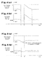
- section (a) shows changes in the main feedback correction value DF
- section (b) shows changes in the instructed injection time tau.
- the main feedback correction value DF stays significantly less than the reference value (0), if the instructed injection time tau becomes less than the permissible minimum time TAUMIN as represented by broken line in section (b) of Fig. 4 (time T1), the main feedback correction value DF is fixed to the reference value (0), as shown in section (a) of Fig. 4 .
- the instructed injection time tau is set to the permissible minimum time TAUMIN regardless of the magnitude of the main feedback correction value DF, the actual air-fuel ratio ABF is not richened due to excessive fuel injection amount in accordance with increase of the main feedback correction value DF.
- the instructed injection time tau reaches or surpasses the permissible minimum time TAUMIN (time T2) immediately after the main feedback correction value DF is fixed to the reference value (0), fixation of the instructed injection time tau to the permissible minimum time TAUMIN is cancelled, and the instructed injection time tau is determined based on the instructed injection amount Q, which is corrected using the correction value DF.
- the main feedback correction value DF is excessively greater in relation to a value immediately before being fixed to the reference value (0), that is, the value immediately before time T1 in the drawing.
- the instructed injection time tau will be significantly greater than the value immediately before the fixation, and the actual air-fuel ratio ABF will become richer than the stoichiometric air-fuel ratio.
- the main feedback correction value DF starts gradually decreasing toward the value immediately before the fixation so that the actual air-fuel ratio ABF becomes the stoichiometric air-fuel ratio according to changes based on the actual air-fuel ratio ABF.
- the instructed injection time tau is gradually decreased as the main feedback correction value DF decreases.
- the main feedback correction value DF starts decreasing from the reference value (0), it takes relatively long time to decrease the correction value DF until the actual air-fuel ratio ABF becomes the stoichiometric air-fuel ratio. Therefore, until the required time elapses (from time T2 to time T3), the actual air-fuel ratio ABF inevitably stays richer than the stoichiometric air-fuel ratio.
- the actual air-fuel ratio ABF is richer than the stoichiometric air-fuel ratio at time T2 and in the period from time T2 to time T3, the actual air-fuel ratio ABF adversely affects the emission and the combustion stability.
- a value of the main feedback correction value DF that permits the instructed injection time tau to be the permissible minimum time TAUMIN is set as a safeguard value G in this embodiment.
- the main feedback correction value DF is safeguarded from falling below the safeguard value G, so that the instructed injection time tau stays longer than the permissible minimum time TAUMIN.
- the main feedback correction value DF starts being changed based on the actual air-fuel ratio ABF from the safeguard value G, but not from the reference value (0). Therefore, immediately after the lower limit safeguard process is cancelled (time T2), correction of the instructed injection amount Q based on the main feedback correction value DF prevents the actual air-fuel ratio ABF from being significantly richer than the stoichiometric air-fuel ratio.
- the starting point of changes in the main feedback correction value DF for causing the actual air-fuel ratio ABF to converge to the stoichiometric air-fuel ratio immediately after the lower limit safeguard process is cancelled is set to the safeguard value G, but not the reference value (0).
- the actual air-fuel ratio ABF is permitted to quickly converge to the stoichiometric air-fuel ratio through the changes, so that the actual air-fuel ratio ABF is prevented from being rich.
- the instructed injection time tau reaches or surpasses the permissible minimum time TAUMIN immediately after being shorter than the permissible minimum time TAUMIN, the actual air-fuel ratio ABF is prevented from being rich, and thus does not adversely affect the emission and the combustion state.
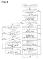
- the safeguard process will now be described with reference to the flowchart of a safeguard process routine shown in Fig. 6 .
- the safeguard process routine is executed as an interrupt by the electronic control unit 8, for example, at predetermined time intervals.
- the safeguard value G used for safeguarding the main feedback correction value DF from falling below the lower limit is computed (S102).
- the safeguard value G is equal to the main feedback correction value DF that causes the instructed injection time tau to be equal to the permissible minimum time TAUMIN.
- the main feedback correction value DF which corresponds to the permissible minimum time TAUMIN, is computed using the following expression (14).
- Expression (14) is obtained by substituting the permissible minimum time TAUMIN for the instructed injection time tau of expression (1), and substituting the right side of expression (2) for the instructed injection amount Q and transforming it.
- the safeguard value G is set as a new value of the main feedback correction value DF (S104). This process safeguards the main feedback correction value DF from falling below the safeguard value G, so that the instructed injection time tau does not become shorter than the permissible minimum time TAUMIN.
- flag F which indicates whether the lower limit safeguard process is being executed for the main feedback correction value DF, set to 1 (safeguard process being executed). Thereafter, various types of processes (S106 to S108) for the lower limit safeguard process are executed in the manner described below.
- flag F is set to 0 (safeguard process is not being executed) at S113. Thereafter, the decision outcome at step S109 is negative and the ⁇ Q clearing process is skipped. Thus, the ⁇ Q clearing process is executed once every time the lower limit safeguard process is cancelled.
- the ⁇ Q accumulation inhibition process is executed during the lower limit safeguard process for the main feedback correction value DF.
- section (b) shows changes in the main feedback correction value DF during the lower limit safeguard process
- section (a) shows changes in the instructed injection time tau during the lower limit safeguard process.
- the fuel amount deviation ⁇ Q based on the actual air-fuel ratio ABF, keeps having a value that decreases the instructed injection amount Q as shown in Fig. 7 (c) , that is, a value greater than 0.
- the accumulation process of the fuel amount deviation accumulated value ⁇ Q that is, expression ( ⁇ Q ⁇ ⁇ Q of the previous cycle + ⁇ Q) is calculated at a predetermined time interval when the correction value DF is limited, the fuel amount deviation accumulated value ⁇ Q changes along broken line shown in section (d) of Fig. 7 .
- the fuel amount deviation accumulated value ⁇ Q is increased, or is changed in a direction decreasing the main feedback correction value DF (instructed injection amount Q).
- the instructed injection amount Q is corrected by the amount corresponding to the integral term ⁇ Q ⁇ Gi in expression (4) by the correction value DF.
- the fuel injection amount is significantly decreased, accordingly. This could lead to a misfire due to lean air-fuel mixture.
- the ⁇ Q accumulation inhibition process is executed when the main feedback correction value DF is limited to the safeguard value G. Specifically, instead of calculating expression (7) at a predetermined time interval, expression (16) ( ⁇ Q ⁇ ⁇ Q of the previous cycle) is calculated to maintain the fuel amount deviation accumulated value ⁇ Q to the value of the previous cycle, thereby inhibiting the accumulation process of the fuel amount deviation accumulated value ⁇ Q. As a result, the fuel amount deviation accumulated value ⁇ Q is maintained to a constant value as shown by solid line in section (d) of Fig. 7 . This prevents, when the correction value DF is limited, the fuel amount deviation accumulated value ⁇ Q (integral term ⁇ Q ⁇ Gi) from being changed in the direction decreasing the instructed injection amount Q. Therefore, when the limit to the correction value DF is cancelled, even if the instructed injection amount Q is corrected by the amount corresponding to the integral term ⁇ Q ⁇ Gi-, a misfire due to lean air-fuel mixture is prevented.
- the accumulation of the fuel amount deviation accumulated value ⁇ Q may be inhibited by a method other than maintaining the fuel amount deviation accumulated value ⁇ Q to the value of the previous cycle. Specifically, the fuel amount deviation accumulated value ⁇ Q may be cleared to 0 as shown by chain double-dashed line in section (d) of Fig. 7 .
- the fuel amount deviation accumulated value ⁇ Q has a value that decreases the main feedback correction value DF (the instructed injection amount Q).
- the instructed injection amount Q is not decreased by the amount corresponding to the integral term ⁇ Q ⁇ Gi. This increases the fuel injection amount.
- the main feedback correction value DF becomes greater than or equal to the safeguard value G, and the limit to the correction value DF is cancelled.
- the correction value DF becomes less than the safeguard value G (the instructed injection time tau becomes less than the permissible minimum time TAUMIN) according to changes in the main feedback correction value DF based on the proportional term ⁇ Q ⁇ Gp, and the main feedback correction value DF is safeguarded from falling below the safeguard value G.
- the MG(i) renewal inhibition process is also executed when the main feedback correction value DF is limited.
- the main feedback correction value DF is prevented from falling below the safeguard value G, so that the instructed injection time tau does not become shorter than the permissible minimum time TAUMIN.
- the main feedback learning value MG(i) is renewed using expression (8) (MG(i) ⁇ the newest DF) based on the main feedback correction value DF after being limited to the safeguard value G, the learning value MG(i) will be renewed to an inappropriate value.
- Section (e) of Fig. 7 shows an example of changes in the main feedback learning value MG(i) in such a situation.
- the MG(i) renewal inhibition process is executed when the correction value DF is limited. Specifically, instead of renewing the main feedback learning value MG(i) using expression (8), expression (17) (MG(i) ⁇ MG(i) of the previous cycle) is calculated to maintain the main feedback learning value MG(i) to the value of the previous cycle, thereby inhibiting the renewal of the learning value MG(i). This prevents the main feedback learning value MG(i) from being renewed to an inappropriate value.
- the VH change and SG renewal inhibition process is also executed when the main feedback correction value DF is limited. Since the rich combustion is performed when the correction value DF is limited, the oxygen concentration of exhaust in the section downstream of the catalysts is less than the value X of the oxygen concentration when the air-fuel mixture is burned at the stoichiometric air-fuel ratio. Accordingly, the output VO of the oxygen sensor 15 becomes greater than the 0.5v. Thus, the voltage deviation ⁇ V of expression (10) is increased, and the sub-feedback correction value VH is decreased. As a result, the main feedback correction value DF (output VAF of the air-fuel ratio sensor 14) tends to be decreased.
- the main feedback correction value DF is limited to the safeguard value G
- the oxygen concentration of exhaust in the section downstream of the catalysts cannot approach the value X
- only the sub-feedback correction value VH is gradually decreased as shown by broken line in section (f) of Fig. 7 . This could cause the correction value VH to diverge.
- the sub-feedback learning value SG which is renewed based on the correction value VH, could be renewed to an inappropriate value.
- the sub-feedback learning value SG is gradually decreased as shown by broken line in section (g) of Fig. 7 , in correspondence with the diverging sub-feedback correction value VH.
- the VH change and SG renewal inhibition process is executed when the correction value DF is limited. More specifically, instead of computing the sub-feedback correction value VH based on expression (10), the sub-feedback correction value VH is maintained to the value of the previous cycle by executing expression (18) (VH ⁇ VH of the previous cycle). Alternatively, the correction value VH is cleared and maintained to 0, so that changes in the correction value VH are inhibited. As a result, the sub-feedback correction value VH is maintained to a constant value as shown by a solid line in section (f) of Fig. 7 .
- the sub-feedback correction value VH and the sub-feedback learning value SG are maintained to constant values to prevent the sub-feedback correction value VH from diverging, and the sub-feedback learning value SG from being renewed to an inappropriate value.
- the ⁇ Q clearing process is executed immediately after the limit to the main feedback correction value DF is cancelled.
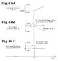
- the period prior to time T4 in the time chart of Fig. 8 corresponds to a state where the correction value DF is limited.
- the correction value DF is limited, if the accelerator pedal 9 is depressed for, for example, acceleration, the throttle valve 3 is opened accordingly so that the intake air amount of the engine 1 is increased.
- the instructed injection amount Q the base fuel injection amount Qbase.
- the safeguard value G computed based on expression (15) is significantly less than the main feedback correction value DF as shown by broken line after time T4 in section (b) of Fig. 8 .
- the instructed injection time tau is extended to be significantly longer than the permissible minimum time TAUMIN as shown by solid line after time T4 in section (a) of Fig. 8 .
- the safeguard value G becomes less than the main feedback correction value DF, and the instructed injection time tau becomes longer than the permissible minimum time TAUMIN as described above, the limit to the correction value DF is cancelled.
- the integral term ⁇ Q ⁇ Gi of the main feedback correction value DF (fuel amount deviation accumulated value ⁇ Q) at the time is under the condition of a sudden increase of the intake air amount.
- the integral term ⁇ Q ⁇ Gi is unreliable in this state.
- the fuel amount deviation accumulated value ⁇ Q is set to 0 as shown in section (c) of Fig. 8 . Accordingly, the integral term ⁇ Q ⁇ Gi is cleared to 0.
- step S110 of the safeguard process routine ( Fig. 6 ) whether the limit to the correction value DF has been cancelled due to increase of the intake air amount is determined based on whether the accelerator pedal 9 is being depressed.
- step S111 based on whether the fuel amount deviation accumulated value ⁇ Q has a positive value, whether the fuel amount deviation accumulated value ⁇ Q has a value decreasing the main feedback correction value DF is determined. If the decision outcomes of step S110 and step S111 are both positive, it is determined that the limit to the correction value DF has been cancelled due to increase of the intake air amount, and the fuel amount deviation accumulated value ⁇ Q has a value decreasing the main feedback correction value DF. Then, at step S112, the fuel amount deviation accumulated value ⁇ Q is set to 0.
- the integral term ⁇ Q ⁇ Gi is cleared to 0. If the integral term ⁇ Q ⁇ Gi (fuel amount deviation accumulated value ⁇ Q) has a value decreasing the main feedback correction value DF, the operation of the engine 1 in an operation region that requires a small amount of fuel injection tends to cause a misfire due to lean air-fuel mixture. Particularly, in the case where the engine 1 is provided with a blowby gas returning device, since in such an operation region the ratio of fuel component derived from blowby gas to the fuel supplied to the combustion chamber 4 is relatively high, the fuel amount deviation accumulated value ⁇ Q is likely to have a value that significantly decreases the main feedback correction value DF. This is likely to cause a misfire due to lean air-fuel mixture. However, since the integral term ⁇ Q ⁇ Gi is cleared to 0 when the reliability of the integral term ⁇ Q ⁇ Gi is lowered, misfire due to lean air-fuel mixture is prevented in the above mentioned operation region.
- step S108 ( Fig. 6 ) of the safeguard process routine, it is not necessary to execute both of the inhibition of changes in the sub-feedback correction value VH and the inhibition of the renewal of the sub-feedback learning value SG, but only one of them may be executed.
- the present invention is not limited to this configuration.
- the determination may be performed based on an increase of the engine load ratio, for example, based on whether an increase of the engine load ratio is equal to or greater than a predetermined value greater than 0. In this case, by adjusting the predetermined value to an optimum value (for example, 2%), the determination is performed accurately.
- Whether the limit to the main feedback correction value DF has been cancelled due to an increase of the intake air amount may be determined based on whether the learning region i of the main feedback learning value MG(i) has been switched during a period from when the limit to the correction value DF is started to when the limit to the correction value DF is cancelled. In this case, based on the fact that the learning region i has been switched, it is determined that the limit to the main feedback correction value DF has been cancelled due to an increase of the intake air amount.
- the intake air amount is changed by such a degree that the learning region i is changed, the reliability of the integral term ⁇ Q ⁇ Gi at the time of canceling the limit to the correction value DF is extremely low. In this case, through the ⁇ Q clearing process, the fuel amount deviation accumulated value ⁇ Q (integral term ⁇ Q ⁇ Gi) can be cleared to 0.
- the fuel amount deviation accumulated value ⁇ Q (integral term ⁇ Q ⁇ Gi) is cleared on the condition that the fuel amount deviation accumulated value ⁇ Q has a value that decreases the feedback correction value DF ( ⁇ Q > 0).
- the fuel amount deviation accumulated value ⁇ Q may be cleared on the condition that expression ⁇ Q ⁇ 0 is satisfied. In this case, step S111 of the safeguard process routine is omitted.
- step S106 Fig. 6
- the fuel amount deviation accumulated value ⁇ Q is maintained to the value of the previous cycle.
- the fuel amount deviation accumulated value ⁇ Q may be cleared to 0. In this case also, a misfire due to lean air-fuel mixture is prevented.
Landscapes
- Engineering & Computer Science (AREA)
- Chemical & Material Sciences (AREA)
- Combustion & Propulsion (AREA)
- Mechanical Engineering (AREA)
- General Engineering & Computer Science (AREA)
- Electrical Control Of Air Or Fuel Supplied To Internal-Combustion Engine (AREA)
- Combined Controls Of Internal Combustion Engines (AREA)
- Exhaust Gas After Treatment (AREA)
Applications Claiming Priority (2)
| Application Number | Priority Date | Filing Date | Title |
|---|---|---|---|
| JP2004364582A JP4453538B2 (ja) | 2004-12-16 | 2004-12-16 | 内燃機関の燃料噴射制御装置 |
| EP05816366A EP1828579B1 (de) | 2004-12-16 | 2005-12-12 | Vorrichtung und verfahren zur steuerung der kraftstoffeinspritzung eines verbrennungsmotors und verbrennungsmotor |
Related Parent Applications (1)
| Application Number | Title | Priority Date | Filing Date |
|---|---|---|---|
| EP05816366.8 Division | 2005-12-12 |
Publications (2)
| Publication Number | Publication Date |
|---|---|
| EP2184471A1 true EP2184471A1 (de) | 2010-05-12 |
| EP2184471B1 EP2184471B1 (de) | 2011-05-18 |
Family
ID=35744690
Family Applications (2)
| Application Number | Title | Priority Date | Filing Date |
|---|---|---|---|
| EP10153352A Expired - Lifetime EP2184471B1 (de) | 2004-12-16 | 2005-12-12 | Vorrichtung und Verfahren zur Steuerung der Kraftstoffeinspritzung eines Verbrennungsmotors, und Verbrennungsmotor |
| EP05816366A Expired - Lifetime EP1828579B1 (de) | 2004-12-16 | 2005-12-12 | Vorrichtung und verfahren zur steuerung der kraftstoffeinspritzung eines verbrennungsmotors und verbrennungsmotor |
Family Applications After (1)
| Application Number | Title | Priority Date | Filing Date |
|---|---|---|---|
| EP05816366A Expired - Lifetime EP1828579B1 (de) | 2004-12-16 | 2005-12-12 | Vorrichtung und verfahren zur steuerung der kraftstoffeinspritzung eines verbrennungsmotors und verbrennungsmotor |
Country Status (7)
| Country | Link |
|---|---|
| US (1) | US7353814B2 (de) |
| EP (2) | EP2184471B1 (de) |
| JP (1) | JP4453538B2 (de) |
| KR (1) | KR100839389B1 (de) |
| CN (1) | CN101080565B (de) |
| DE (1) | DE602005020352D1 (de) |
| WO (1) | WO2006064924A1 (de) |
Families Citing this family (14)
| Publication number | Priority date | Publication date | Assignee | Title |
|---|---|---|---|---|
| JP4574610B2 (ja) * | 2006-12-15 | 2010-11-04 | 本田技研工業株式会社 | 内燃機関の制御装置 |
| JP4835497B2 (ja) | 2007-04-13 | 2011-12-14 | トヨタ自動車株式会社 | 内燃機関の空燃比制御装置 |
| JP2009002251A (ja) * | 2007-06-22 | 2009-01-08 | Toyota Motor Corp | 内燃機関の空燃比制御装置 |
| JP5026188B2 (ja) * | 2007-08-10 | 2012-09-12 | 株式会社デンソー | 車両用制御装置及び車両用制御システム |
| JP2009221881A (ja) * | 2008-03-13 | 2009-10-01 | Yanmar Co Ltd | エンジン |
| JP4530080B2 (ja) * | 2008-06-20 | 2010-08-25 | トヨタ自動車株式会社 | 内燃機関の制御装置 |
| JP5411728B2 (ja) * | 2010-01-28 | 2014-02-12 | 本田技研工業株式会社 | 内燃機関の空燃比学習制御装置 |
| US8922198B2 (en) | 2010-10-26 | 2014-12-30 | Blackberry Limited | System and method for calibrating a magnetometer according to a quality threshold |
| DE102010063119A1 (de) * | 2010-12-15 | 2012-06-21 | Robert Bosch Gmbh | Verfahren zur Regelung und Adaption eines Luft-/Kraftstoffgemischs in einem Verbrennungsmotor |
| SE538206C2 (sv) * | 2012-07-05 | 2016-04-05 | Scania Cv Ab | Förfarande och system vid framförande av fordon, där luft/bränsleförhållandet styrs |
| JP5648706B2 (ja) * | 2013-04-19 | 2015-01-07 | トヨタ自動車株式会社 | 内燃機関の空燃比制御装置 |
| JP6102908B2 (ja) * | 2014-12-26 | 2017-03-29 | トヨタ自動車株式会社 | 排気浄化装置の劣化診断装置 |
| FR3061746B1 (fr) * | 2017-01-10 | 2020-09-25 | Continental Automotive France | Procede de correction d'une duree d'injection de carburant dans un cylindre de moteur thermique de vehicule automobile |
| CN115135865A (zh) * | 2020-03-02 | 2022-09-30 | 沃尔沃卡车集团 | 具有燃料系统控制装置的发动机系统和用于控制内燃发动机中的燃料喷射的方法 |
Citations (6)
| Publication number | Priority date | Publication date | Assignee | Title |
|---|---|---|---|---|
| JPS6022053A (ja) | 1983-07-18 | 1985-02-04 | Toyota Motor Corp | 電子制御燃料噴射式エンジンの空燃比フィードバック制御装置 |
| US4878472A (en) * | 1987-08-31 | 1989-11-07 | Honda Giken Kogyo K.K. | Air-fuel ratio feedback control method for internal combustion engines |
| US5220904A (en) * | 1991-08-30 | 1993-06-22 | Honda Giken Kogyo Kabushiki Kaisha | Air-fuel ratio control system for internal combustion engines |
| US5762055A (en) * | 1995-06-27 | 1998-06-09 | Nippondenso Co., Ltd. | Air-to-fuel ratio control apparatus for an internal combustion engine |
| DE19859824A1 (de) | 1997-12-25 | 1999-07-08 | Hitachi Ltd | Steuervorrichtung zum Einspritzen von Kraftstoff und Verfahren zum Einspritzen von Kraftstoff |
| EP1469182A1 (de) * | 2003-04-15 | 2004-10-20 | Toyota Jidosha Kabushiki Kaisha | Steuerungsvorrichtung für das Kraftstoff/-Luftverhältnis einer Brennkraftmaschine |
Family Cites Families (8)
| Publication number | Priority date | Publication date | Assignee | Title |
|---|---|---|---|---|
| JPS63189656A (ja) | 1987-01-31 | 1988-08-05 | Mazda Motor Corp | エンジンの燃料制御装置 |
| JPH01110856A (ja) | 1987-10-21 | 1989-04-27 | Mazda Motor Corp | エンジンの空燃比制御装置 |
| US5224462A (en) * | 1992-08-31 | 1993-07-06 | Ford Motor Company | Air/fuel ratio control system for an internal combustion engine |
| US5566662A (en) * | 1995-10-02 | 1996-10-22 | Ford Motor Company | Engine air/fuel control system with an adaptively learned range of authority |
| JP3644172B2 (ja) * | 1997-01-16 | 2005-04-27 | 日産自動車株式会社 | エンジンの空燃比制御装置 |
| DE69923762T2 (de) * | 1999-03-29 | 2006-01-19 | Toyota Jidosha K.K., Toyota | Steuerungsvorrichtung für das Kraftstoff/-Luftverhältnis in einer Brennkraftmaschine |
| JP3695213B2 (ja) * | 1999-04-02 | 2005-09-14 | いすゞ自動車株式会社 | コモンレール式燃料噴射装置 |
| JP2004060613A (ja) | 2002-07-31 | 2004-02-26 | Toyota Motor Corp | 内燃機関の空燃比制御装置 |
-
2004
- 2004-12-16 JP JP2004364582A patent/JP4453538B2/ja not_active Expired - Lifetime
-
2005
- 2005-12-12 EP EP10153352A patent/EP2184471B1/de not_active Expired - Lifetime
- 2005-12-12 DE DE602005020352T patent/DE602005020352D1/de not_active Expired - Lifetime
- 2005-12-12 EP EP05816366A patent/EP1828579B1/de not_active Expired - Lifetime
- 2005-12-12 KR KR1020077013593A patent/KR100839389B1/ko not_active Expired - Lifetime
- 2005-12-12 CN CN2005800433948A patent/CN101080565B/zh not_active Expired - Lifetime
- 2005-12-12 WO PCT/JP2005/023190 patent/WO2006064924A1/en not_active Ceased
- 2005-12-13 US US11/299,677 patent/US7353814B2/en not_active Expired - Lifetime
Patent Citations (6)
| Publication number | Priority date | Publication date | Assignee | Title |
|---|---|---|---|---|
| JPS6022053A (ja) | 1983-07-18 | 1985-02-04 | Toyota Motor Corp | 電子制御燃料噴射式エンジンの空燃比フィードバック制御装置 |
| US4878472A (en) * | 1987-08-31 | 1989-11-07 | Honda Giken Kogyo K.K. | Air-fuel ratio feedback control method for internal combustion engines |
| US5220904A (en) * | 1991-08-30 | 1993-06-22 | Honda Giken Kogyo Kabushiki Kaisha | Air-fuel ratio control system for internal combustion engines |
| US5762055A (en) * | 1995-06-27 | 1998-06-09 | Nippondenso Co., Ltd. | Air-to-fuel ratio control apparatus for an internal combustion engine |
| DE19859824A1 (de) | 1997-12-25 | 1999-07-08 | Hitachi Ltd | Steuervorrichtung zum Einspritzen von Kraftstoff und Verfahren zum Einspritzen von Kraftstoff |
| EP1469182A1 (de) * | 2003-04-15 | 2004-10-20 | Toyota Jidosha Kabushiki Kaisha | Steuerungsvorrichtung für das Kraftstoff/-Luftverhältnis einer Brennkraftmaschine |
Also Published As
| Publication number | Publication date |
|---|---|
| JP2006170098A (ja) | 2006-06-29 |
| KR100839389B1 (ko) | 2008-06-19 |
| EP1828579B1 (de) | 2010-03-31 |
| DE602005020352D1 (de) | 2010-05-12 |
| CN101080565B (zh) | 2010-08-11 |
| CN101080565A (zh) | 2007-11-28 |
| US7353814B2 (en) | 2008-04-08 |
| EP1828579A1 (de) | 2007-09-05 |
| JP4453538B2 (ja) | 2010-04-21 |
| KR20070086286A (ko) | 2007-08-27 |
| US20060130457A1 (en) | 2006-06-22 |
| WO2006064924A1 (en) | 2006-06-22 |
| EP2184471B1 (de) | 2011-05-18 |
Similar Documents
| Publication | Publication Date | Title |
|---|---|---|
| EP1828579B1 (de) | Vorrichtung und verfahren zur steuerung der kraftstoffeinspritzung eines verbrennungsmotors und verbrennungsmotor | |
| US8406980B2 (en) | Air-fuel ratio control device and air-fuel ratio control method for internal combustion engine | |
| EP2245288B1 (de) | Vorrichtung und verfahren zur steuerung des kraftstoff-luft-verhältnisses einer brennkraftmaschine | |
| CN101636568B (zh) | 内燃机的催化剂劣化判断装置 | |
| US9328681B2 (en) | Control apparatus for internal combustion engine | |
| US6644017B2 (en) | Device for and method of controlling air-fuel ratio of internal combustion engine | |
| US7788903B2 (en) | Air-fuel ratio control apparatus of internal combustion engine | |
| EP1469182A1 (de) | Steuerungsvorrichtung für das Kraftstoff/-Luftverhältnis einer Brennkraftmaschine | |
| EP2133529B1 (de) | Verschlechterungsbestimmungsvorrichtung für einen Katalysator, und Katalysatorverschlechterungsbestimmungsverfahren | |
| JP2010007561A (ja) | 空燃比制御装置及び空燃比制御方法 | |
| EP0531546B1 (de) | Luft-/kraftstoffverhältnis-steuereinrichtung für brennkraftmaschinen | |
| JP2006170098A5 (de) | ||
| JP2009167944A (ja) | 内燃機関の燃料噴射制御装置 | |
| JP4353070B2 (ja) | 内燃機関の空燃比制御装置 | |
| JPH06307271A (ja) | エンジンの空燃比制御装置 | |
| JP2011196317A (ja) | 異常診断装置 | |
| US9255532B2 (en) | Air-fuel ratio control system of internal combustion engine | |
| US20070169465A1 (en) | Air-fuel ratio control apparatus for internal combustion engine | |
| JP4190430B2 (ja) | 酸素センサの異常診断装置 | |
| US6513510B2 (en) | Method for controlling fuel supply of a vehicle on acceleration and a system thereof | |
| JP4494439B2 (ja) | 内燃機関の空燃比制御装置 | |
| JP4888365B2 (ja) | 内燃機関の空燃比制御装置 | |
| JPH11173194A (ja) | エンジンの空燃比制御装置 |
Legal Events
| Date | Code | Title | Description |
|---|---|---|---|
| PUAI | Public reference made under article 153(3) epc to a published international application that has entered the european phase |
Free format text: ORIGINAL CODE: 0009012 |
|
| 17P | Request for examination filed |
Effective date: 20100211 |
|
| AC | Divisional application: reference to earlier application |
Ref document number: 1828579 Country of ref document: EP Kind code of ref document: P |
|
| AK | Designated contracting states |
Kind code of ref document: A1 Designated state(s): DE FR GB |
|
| RIC1 | Information provided on ipc code assigned before grant |
Ipc: F02D 41/14 20060101AFI20101111BHEP |
|
| GRAP | Despatch of communication of intention to grant a patent |
Free format text: ORIGINAL CODE: EPIDOSNIGR1 |
|
| GRAS | Grant fee paid |
Free format text: ORIGINAL CODE: EPIDOSNIGR3 |
|
| GRAA | (expected) grant |
Free format text: ORIGINAL CODE: 0009210 |
|
| REG | Reference to a national code |
Ref country code: GB Ref legal event code: FG4D |
|
| REG | Reference to a national code |
Ref country code: DE Ref legal event code: R096 Ref document number: 602005028188 Country of ref document: DE Effective date: 20110630 |
|
| PLBE | No opposition filed within time limit |
Free format text: ORIGINAL CODE: 0009261 |
|
| STAA | Information on the status of an ep patent application or granted ep patent |
Free format text: STATUS: NO OPPOSITION FILED WITHIN TIME LIMIT |
|
| 26N | No opposition filed |
Effective date: 20120221 |
|
| REG | Reference to a national code |
Ref country code: DE Ref legal event code: R097 Ref document number: 602005028188 Country of ref document: DE Effective date: 20120221 |
|
| REG | Reference to a national code |
Ref country code: GB Ref legal event code: 746 Effective date: 20120918 |
|
| REG | Reference to a national code |
Ref country code: DE Ref legal event code: R084 Ref document number: 602005028188 Country of ref document: DE Effective date: 20120924 |
|
| REG | Reference to a national code |
Ref country code: FR Ref legal event code: PLFP Year of fee payment: 11 |
|
| REG | Reference to a national code |
Ref country code: FR Ref legal event code: PLFP Year of fee payment: 12 |
|
| REG | Reference to a national code |
Ref country code: FR Ref legal event code: PLFP Year of fee payment: 13 |
|
| P01 | Opt-out of the competence of the unified patent court (upc) registered |
Effective date: 20230427 |
|
| PGFP | Annual fee paid to national office [announced via postgrant information from national office to epo] |
Ref country code: DE Payment date: 20241029 Year of fee payment: 20 |
|
| PGFP | Annual fee paid to national office [announced via postgrant information from national office to epo] |
Ref country code: GB Payment date: 20241104 Year of fee payment: 20 |
|
| PGFP | Annual fee paid to national office [announced via postgrant information from national office to epo] |
Ref country code: FR Payment date: 20241111 Year of fee payment: 20 |
|
| REG | Reference to a national code |
Ref country code: DE Ref legal event code: R071 Ref document number: 602005028188 Country of ref document: DE |
|
| REG | Reference to a national code |
Ref country code: GB Ref legal event code: PE20 Expiry date: 20251211 |