EP2184510B1 - Schaltanordnung - Google Patents
Schaltanordnung Download PDFInfo
- Publication number
- EP2184510B1 EP2184510B1 EP20090173108 EP09173108A EP2184510B1 EP 2184510 B1 EP2184510 B1 EP 2184510B1 EP 20090173108 EP20090173108 EP 20090173108 EP 09173108 A EP09173108 A EP 09173108A EP 2184510 B1 EP2184510 B1 EP 2184510B1
- Authority
- EP
- European Patent Office
- Prior art keywords
- sliding sleeve
- range group
- centring
- toothing
- group according
- Prior art date
- Legal status (The legal status is an assumption and is not a legal conclusion. Google has not performed a legal analysis and makes no representation as to the accuracy of the status listed.)
- Not-in-force
Links
- 230000005540 biological transmission Effects 0.000 claims description 18
- 238000006073 displacement reaction Methods 0.000 claims description 7
- 230000008878 coupling Effects 0.000 description 48
- 238000010168 coupling process Methods 0.000 description 48
- 238000005859 coupling reaction Methods 0.000 description 48
- 230000007935 neutral effect Effects 0.000 description 5
- 230000015572 biosynthetic process Effects 0.000 description 3
- 238000005755 formation reaction Methods 0.000 description 3
- 230000007704 transition Effects 0.000 description 2
- 238000010276 construction Methods 0.000 description 1
- 230000001419 dependent effect Effects 0.000 description 1
- 238000011161 development Methods 0.000 description 1
- 230000018109 developmental process Effects 0.000 description 1
- 230000000694 effects Effects 0.000 description 1
- 238000004519 manufacturing process Methods 0.000 description 1
- 238000005096 rolling process Methods 0.000 description 1
- 238000010008 shearing Methods 0.000 description 1
- 239000007787 solid Substances 0.000 description 1
- 230000001360 synchronised effect Effects 0.000 description 1
Images

Classifications
-
- F—MECHANICAL ENGINEERING; LIGHTING; HEATING; WEAPONS; BLASTING
- F16—ENGINEERING ELEMENTS AND UNITS; GENERAL MEASURES FOR PRODUCING AND MAINTAINING EFFECTIVE FUNCTIONING OF MACHINES OR INSTALLATIONS; THERMAL INSULATION IN GENERAL
- F16H—GEARING
- F16H3/00—Toothed gearings for conveying rotary motion with variable gear ratio or for reversing rotary motion
- F16H3/44—Toothed gearings for conveying rotary motion with variable gear ratio or for reversing rotary motion using gears having orbital motion
- F16H3/46—Gearings having only two central gears, connected by orbital gears
- F16H3/48—Gearings having only two central gears, connected by orbital gears with single orbital gears or pairs of rigidly-connected orbital gears
- F16H3/52—Gearings having only two central gears, connected by orbital gears with single orbital gears or pairs of rigidly-connected orbital gears comprising orbital spur gears
- F16H3/54—Gearings having only two central gears, connected by orbital gears with single orbital gears or pairs of rigidly-connected orbital gears comprising orbital spur gears one of the central gears being internally toothed and the other externally toothed
-
- F—MECHANICAL ENGINEERING; LIGHTING; HEATING; WEAPONS; BLASTING
- F16—ENGINEERING ELEMENTS AND UNITS; GENERAL MEASURES FOR PRODUCING AND MAINTAINING EFFECTIVE FUNCTIONING OF MACHINES OR INSTALLATIONS; THERMAL INSULATION IN GENERAL
- F16D—COUPLINGS FOR TRANSMITTING ROTATION; CLUTCHES; BRAKES
- F16D11/00—Clutches in which the members have interengaging parts
- F16D11/08—Clutches in which the members have interengaging parts actuated by moving a non-rotating part axially
- F16D11/10—Clutches in which the members have interengaging parts actuated by moving a non-rotating part axially with clutching members movable only axially
-
- F—MECHANICAL ENGINEERING; LIGHTING; HEATING; WEAPONS; BLASTING
- F16—ENGINEERING ELEMENTS AND UNITS; GENERAL MEASURES FOR PRODUCING AND MAINTAINING EFFECTIVE FUNCTIONING OF MACHINES OR INSTALLATIONS; THERMAL INSULATION IN GENERAL
- F16D—COUPLINGS FOR TRANSMITTING ROTATION; CLUTCHES; BRAKES
- F16D11/00—Clutches in which the members have interengaging parts
- F16D2011/004—Clutches in which the members have interengaging parts using an internal or intermediate axially slidable sleeve, coupling both components together, whereby the intermediate sleeve is arranged internally at least with respect to one of the components
Definitions
- the present invention relates to a planetary construction executed range group of a multi-group transmission with a jaw-connected switching arrangement according to the preamble of patent claim 1, and a multi-group transmission with a range group and such a switching arrangement, according to claim 9.
- two switching elements to be coupled together for example a sliding sleeve and a coupling body, can be aligned concentrically with each other by means of synchronizing rings during the synchronizing and switching operation, so that a smooth engagement is possible.
- switching arrangements without mechanical synchronizing device which are also called claw-connected switching arrangements, such an orientation is not possible.
- a narrow ring gear toothing can only ensure less accurate mounting and guidance of the sliding sleeve. This creates the problem that the Schlebemuffe tilts when inserting a gear out of its axial orientation. In this case, the coupling teeth of the sliding sleeve is offset from the counter-toothing and easy coupling is no longer possible even with synchronous operation of the two coupling teeth.
- a planetary design executed range group of a multi-group transmission is proposed with a jaw-connected switching arrangement, wherein the sun gear with the drive shaft, the planet carrier with the output shaft and the ring gear rotatably connected to a sliding sleeve is.
- the sliding sleeve is provided with an external toothing, which is rotatably connected in the axial displacement of the sliding sleeve in a first direction with the coupling teeth of a rigidly connected to the planet carrier coupling body and by axial displacement in a second direction with the coupling teeth of a housing-fixed coupling body.
- the sliding sleeve can be moved axially by a engaging the inner diameter of the sliding sleeve switching element.
- At least one centering collar is arranged on the sliding sleeve and / or on at least one of the two coupling bodies in an axial extension to the respective external toothing or coupling toothing.
- the centering collar ensures that the two external teeth and coupling teeth to be coupled to one another are positioned concentrically with one another during the switching operation at their respective end region where they meet one another. Thereafter, the external teeth and the coupling teeth can be smoothly engaged with each other, as soon as synchronism between the sliding sleeve and the coupling body and a "tooth-on-gap" position between the external teeth and the coupling teeth is reached.
- the arrangement according to the invention requires less space in the radial direction than the sliding sleeve actuated on its outer circumference by the switching element arranged inside the sliding sleeve and acting on its inner surface for actuating the sliding sleeve. Thanks to the Zentrierbundes invention also satisfies a relatively narrow storage of the sliding sleeve in the axial direction, because the sliding sleeve of the storage no longer needs to be kept exactly coaxial with the central axis. Slight deviations in the form of a tilting of the sliding sleeve from its coaxial position to the central axis are corrected during the switching operation by the centering collar.
- the circuit arrangement according to the invention thus requires a total of little space and is still safely and smoothly switchable.
- the centering collar preferably has a conical, arranged coaxially to the central axis of the associated external toothing centering, wherein the largest diameter of the conical centering surface according to a particularly preferred embodiment corresponds to the root diameter of the associated external toothing.
- the conical centering surface preferably extends at an angle between 5 ° and 15 ° to the central axis of the sliding sleeve or the respective coupling teeth.
- An adjoining the smallest diameter of the conical centering surface of the centering collar extends according to a further preferred embodiment of the switching arrangement at an angle of more than 15 ° to the central axis. With the help of this ramp surface, the shearing of the centering collar is facilitated in the opposite coupling teeth. The same effect can be achieved by providing a rounded chamfer at the smallest diameter of the centering collar.
- the centering of the Zentrierbundes in the axial direction is preferably arranged directly adjacent to the corresponding external teeth or coupling teeth.
- a further preferred embodiment of the invention provides that the centering collar is designed in one piece with the sliding sleeve or with the respective coupling body. In this way, a solid connection between the components is created.
- the centering collar can be rotated and processed according to this embodiment in the manufacture of the sliding sleeve or the coupling body in one step with other formations of the components.
- the correct position of the centering collar to the axis of rotation can be achieved with less effort, because the centering collar can be edited, for example, in a single clamping with the sliding sleeve.
- the present invention includes a multi-group transmission having a switching arrangement as described above. Due to the compact design of the switching arrangement, such a vehicle transmission requires less space overall and can be built more easily.
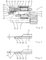
- the range group of the multi-group transmission according to the invention has, as in Fig. 1 shown, a planetary gear set 7, which consists essentially of a sun gear 1, a planet carrier 2 with planetary gears 3 and a ring gear 4. Each planetary gear 3 is rotatably supported by rolling bearings 5 on a pin 6 in the planet carrier 2. The components of the planetary gear set 7 are arranged rotatably about a central axis 20.
- the power flow in the range group extends from the main group coming via the drive shaft 21, the sun gear 1, the planet gears 3, the planet carrier 2 to an output shaft, not shown, which is rigidly connected to the planet carrier 2.
- the drive shaft 21 may be, for example, the output shaft of the main group of the multi-group transmission.
- a sliding sleeve 12 is arranged laterally to the planetary gear set 7 and rotatably connected via a ring gear 8 with the ring gear 4.
- the ring gear 8 has a hollow wheel side outer teeth 9, which engages in the internal toothing 10 of the ring gear 4.
- An internal toothing 11 at the other end of the Hohlradlys 8 engages in an external toothing 13 of the sliding sleeve 12 a.
- the sliding sleeve 12 is axially displaceable.
- An actuatable in the axial direction switching element 15 engages in a groove 14 on the inner diameter of the sliding sleeve 12 a.
- the switching element 15 is actuated for example by a pressure-medium-actuated cylinder-piston unit, not shown, or by an electric drive.
- At least two switching positions are possible for the switching arrangement and the sliding sleeve.
- a first shift position in which the input speed of the drive shaft 21 is transmitted unchanged as output speed to the planet carrier 2 and a second shift position, wherein the input speed of the drive shaft 21 to a lower output speed of the planet carrier 2 is translated.
- a third shift position namely a neutral position lying between the first and second shift positions.
- Fig. 1 the sliding sleeve is still in the neutral position.
- the sliding sleeve 12 is already actuated by the switching element 15 in the direction of the first switching position.
- the sliding sleeve 12 is mounted on its external teeth 13 in the internal teeth 11 of the Hohlradismes 8.
- the sliding sleeve relative to the ring gear 8 in the axial direction should be as easy as possible to move, this storage is subject to a relatively large game.
- the rotating sliding sleeve 12 relative to the fixed in the direction of rotation switching element 15 must be rotated as smoothly as possible.
- the sliding sleeve 12 tends to tilt out of its coaxial position relative to the central axis 20 during axial actuation.
- a tilted position of the sliding sleeve 12 is in Fig. 1 shown.
- the tilt angle of the sliding sleeve 12 is in Fig. 1 shown enlarged in order to make the tilted position clearly visible.
- Such a tilting leads in conventional sliding sleeves to the fact that the sliding sleeve clamps during the axial displacement and that the switching operation, if at all, only with great effort and jerky possible.
- the sliding sleeve 12 is equipped with the centering collar 22 which on the sliding sleeve in the axial extension of the external teeth 13 in Direction of the coupling body 19 is arranged.
- the centering collar 22 centers the external teeth 13 and the coupling teeth 18 during the axial displacement of the sliding sleeve 12 to each other and guides the two gears exactly and steplessly into each other.
- the centering collar 22 no longer touches the coupling teeth 18.
- the torque is transmitted solely via the external teeth 13 on the coupling teeth 18.
- Fig. 2 shows the same components as Fig. 1 , therefore, the same components are also provided with the same reference numerals and not described again here.
- the sliding sleeve 12 In the second switching position, not shown, the sliding sleeve 12 is displaced axially to the left and the external teeth 13 of the sliding sleeve engages in a coupling toothing 17 of a housing-fixed coupling body 16 a.
- the ring gear 4 via the ring gear 8, the sliding sleeve 12 and the coupling body 16 rotatably connected to the transmission housing.
- the input speed of the drive shaft 21 is translated by the planetary gear 7 to a lower output speed of the planetary carrier 2.
- the sliding sleeve 12 has a further centering collar 23, which is arranged on the sliding sleeve in the axial extension of the external toothing 13 in the direction of the housing-mounted coupling body 16.
- the centering collar 23 centers the external teeth 13 and the coupling teeth 17 to each other during the axial displacement the sliding sleeve 12 to the left.
- About the centering collar 23 slides the sliding sleeve 12 so in the coupling body 16 that the two gears can intervene jerk-free and without much effort into each other, once equal speed and a "tooth-on-gap" position are reached.
- the centering collar 23 no longer touches the coupling toothing 17.
- a further embodiment of the switching arrangement according to the invention is shown in the neutral position.
- This embodiment differs from the embodiments described above only in that, in addition to the centering collars 22 and 23 on the sliding sleeve 12, a centering collar 25 is arranged on the coupling body 16 and a centering collar 24 on the coupling body 19. With these additional Zentrierbünden 24 and 25, the switching operation is further improved in the respective switching position and possible signs of wear on the coupling teeth 17 and 18 through the centering collars 22 and 23 can be reduced.
- the present invention also includes embodiments in which instead of the centering collars 22 and 23 on the sliding sleeve only the centering collars 24 and 25 are provided on the coupling bodies. Likewise, embodiments are conceivable in which alternately a respective centering collar are provided on the Schlebemuffe and on a coupling body, for. B. centering collars 23 with 24 or 25 with 22nd
- FIG. 4 and FIG. 5 show in a detail shown enlarged from the sliding sleeve each particular formations of Zentrierbundes 23. In accordance mirrored execution these special formations of Zentrierbundes 23 are also applicable to the Zentrierbünden 22, 24 and 25.
- the centering collar 23 has on its outer circumference a conical centering surface 26.
- the angle of inclination a of the centering surface with respect to the axis of rotation of the sliding sleeve may have a value between 5 and 15 degrees. In the Fig. 4 the angle of inclination a is applied to the external toothing 13 of the sliding sleeve 12 because the external toothing 13 extends coaxially to the axis of rotation of the sliding sleeve 12.
- the largest diameter of the conical centering surface 26 corresponds to the Wenn Vietnamese silkmesser F of the external teeth 13 of the sliding sleeve 12, so that a steady, continuous transition between the centering surface 26 and the cancelled Vietnamese the outer toothing 13 is present over the outer teeth 13 of the sliding sleeve 12 smoothly and smoothly in the Coupling teeth 17 of the housing-fixed coupling body 16 can slide.
- the centering surface 26 abuts directly on the external toothing 13. In other words, the centering surface 26 passes directly into the outer toothing 13, whereby the space in the axial direction is optimally utilized.
- the centering collar 23 remote from the external toothing 13 the centering collar has a rounded bevel 27.
- Fig. 5 shown embodiment of the Zentrierbundes 23 differs from the execution in Fig. 4 by an additional ramp surface 28.
- the ramp surface 28 extends at an angle b to the central axis 21, which is greater than 15 degrees.
- the conical ramp surface 28 lies with its largest diameter directly on the smallest diameter of the likewise conical centering surface 26. The transition from the centering surface 26 to the ramp surface 28 is advantageously rounded.
Landscapes
- Engineering & Computer Science (AREA)
- General Engineering & Computer Science (AREA)
- Mechanical Engineering (AREA)
- Structure Of Transmissions (AREA)
- Mechanical Operated Clutches (AREA)
Description
- Die vorliegende Erfindung betrifft eine in Planetenbauweise ausgeführte Bereichsgruppe eines Mehrgruppengetriebes mit einer klauengeschalteten Schaltanordnung gemäß dem Oberbegriff des Patentanspruchs 1, sowie ein Mehrgruppengetriebe mit einer Bereichsgruppe und einer derartigen Schaltanordnung, gemäß Patentanspruch 9.
- In Schaltgetrieben wird zum Einschalten einer gewünschten Übersetzung häufig eine auf einer zentralen Welle gelagerte Schiebemuffe mit einer ersten Kupplungsverzahnung axial verschoben, um mit einem der gewünschten Übersetzung zugeordneten Kupplungskörper mit einer zweiten Kupplungsverzahnung drehfest verbunden zu werden. Um die beiden Kupplungsverzahnungen möglichst zügig und ruckfrei miteinander in Eingriff zu bringen, ist neben dem Synchronlauf zwischen der Schiebemuffe und dem Kupplungskörper, bzw. deren Kupplungsverzahnungen, auch eine konzentrische Ausrichtung der beiden Kupplungsverzahnungen notwendig.
- Bei Schaltanordnungen mit mechanischen Synchronisiervorrichtungen können zwei miteinander zu kuppelnde Schaltelemente, beispielsweise eine Schiebemuffe und ein Kupplungskörper, mit Hilfe von Synchronringen während des Synchronisier- und Schaltvorganges konzentrisch zueinander ausgerichtet werden, so dass ein ruckfreies Einkuppeln möglich ist. Bei Schaltanordnungen ohne mechanische Synchronisiervorrichtung, die auch klauengeschaltete Schaltanordnungen genannt werden, ist eine derartige Ausrichtung nicht möglich.
- Aus der
DE 10 2005 021 698 A1 ist eine klauengeschaltete Schaltanordnung für eine in Planetenbauweise ausgeführte Nachschaltgruppe eines Mehrgruppengetriebes bekannt, bei der eine Schiebemuffe nicht auf einer zentralen Welle gelagert ist, sondern in einem Hohlradträger, der in eine am äußeren Umfang der Schiebemuffe angeordnete Außenverzahnung der Schiebemuffe eingreift. Dieses Getriebe weist keine mechanische Synchronisierung auf. Zur sicheren Führung der Schiebemuffe wird in derDE 10 2005 021 698 A1 vorgeschlagen, die Hohlradträgerverzahnung breit auszuführen. Dadurch steigt jedoch der Bauraumbedarf für diese Art der Schaltanordnung. - Eine schmale Hohlradträgerverzahnung kann dagegen nur eine weniger genaue Lagerung und Führung der Schiebemuffe sicherstellen. Dadurch entsteht das Problem, dass die Schlebemuffe beim Einlegen eines Ganges aus ihrer axialen Ausrichtung heraus kippt. Dabei wird die Kupplungsverzahnung der Schiebemuffe versetzt zu der Gegenverzahnung und ein problemloses Einkoppeln ist auch bei Synchronlauf der beiden Kupplungsverzahnungen nicht mehr möglich.
- Es ist nun Aufgabe der vorliegenden Erfindung, eine Schaltanordnung für die Bereichsgruppe eines Mehrgruppengetriebes der beschriebenen Art zu schaffen, die wenig Bauraum benötigt und sicher und ruckfrei schaltbar ist. Des Weiteren soll ein Mehrgruppengetriebe mit einer derartigen Schaltanordnung geschaffen werden.
- Gelöst wird diese Aufgabe durch eine Schaltanordnung mit den Merkmalen des Patentanspruchs 1 und durch ein Mehrgruppengetriebe mit einer solchen Schaltanordnung gemäß Patentanspruch 9. Vorteilhafte Weiterbildungen sind in den abhängigen Ansprüchen beschrieben.
- Demnach wird eine in Planetenbauweise ausgeführte Bereichsgruppe eines Mehrgruppengetriebes mit einer klauengeschalteten Schaltanordnung vorgeschlagen, wobei das Sonnenrad mit der Antriebswelle, der Planetenträger mit der Abtriebswelle und das Hohlrad mit einer Schiebemuffe drehfest verbunden ist. Die Schiebemuffe ist dabei mit einer Aussenverzahnung versehen, die beim axialen Verschieben der Schiebemuffe in eine erste Richtung mit der Kupplungsverzahnung eines starr mit dem Planetenträger verbundenen Kupplungskörpers und durch axiales Verschieben in eine zweite Richtung mit der Kupplungsverzahnung eines gehäusefesten Kupplungskörpers drehfest verbindbar ist. Die Schiebemuffe kann durch ein am Innendurchmesser der Schiebemuffe angreifendes Schaltelement axial verschoben werden.
- Erfindungsgemäß ist an der Schiebemuffe und/oder an mindestens einem der beiden Kupplungskörper zumindest ein Zentrierbund in axialer Verlängerung zu der jeweiligen Aussenverzahnung bzw. Kupplungsverzahnung angeordnet.
- Der Zentrierbund sorgt dafür, dass die beiden miteinander zu koppelnde Aussenverzahnung und Kupplungsverzahnung während des Schaltvorganges an ihrem jeweiligen Endbereich, an dem sie aufeinander treffen, konzentrisch zueinander positioniert werden. Danach können die Aussenverzahnung und die Kupplungsverzahnungen ruckfrei miteinander in Eingriff gebracht werden, sobald Synchronlauf zwischen der Schiebemuffe und dem Kupplungskörper und eine"Zahn-auf-Lücke"-Stellung zwischen der Aussenverzahnung und der Kupplungsverzahnung erreicht ist.
- Die erfindungsgemäße Anordnung benötigt durch das innerhalb der Schiebemuffe angeordnete und an deren Innenfläche angreifende Schaltelement zum Betätigen der Schiebemuffe weniger Bauraum in radialer Richtung als eine an ihrem Außenumfang betätigte Schiebemuffe. Dank des erfindungsgemäßen Zentrierbundes genügt auch eine verhältnismäßig schmale Lagerung der Schiebemuffe in axialer Richtung, weil die Schiebemuffe von der Lagerung nicht mehr exakt koaxial zur Mittelachse gehalten werden muss. Leichte Abweichungen in Form eines Kippens der Schaltmuffe aus ihrer koaxialen Lage zur Mittelachse werden während des Schaltvorganges durch den Zentrierbund korrigiert. Die erfindungsgemäße Schaltanordnung benötigt also insgesamt wenig Bauraum und ist trotzdem sicher und ruckfrei schaltbar.
- Der Zentrierbund weist bevorzugt eine konische, koaxial zu der Mittelachse der dazugehörigen Aussenverzahnung angeordnete Zentrierfläche auf, wobei der größte Durchmesser der konischen Zentrierfläche gemäß einer besonders bevorzugten Ausführung dem Fußkreisdurchmesser der dazugehörigen Aussenverzahnung entspricht. Diese Ausführung des Zentrierbundes und der Zentrierfläche gewährleistet, dass die miteinander zu verbindende Aussenverzahnung und Kupplungsverzahnung nach dem Zentrieren durch den Zentrierbund stufenlos und ruckfrei ineinander geführt werden.
- Die konische Zentrierfläche verläuft vorzugsweise in einem Winkel zwischen 5° und 15° zu der Mittelachse der Schiebemuffe bzw. der jeweiligen Kupplungsverzahnung. Eine am kleinsten Durchmesser der konischen Zentrierfläche anschließende Auflauffläche des Zentrierbundes verläuft gemäß einer weiteren bevorzugten Ausgestaltung der Schaltanordnung in einem Winkel von mehr als 15° zu der Mittelachse. Mit Hilfe dieser Auflauffläche wird das Einscheren des Zentrierbundes in die gegenüberliegende Kupplungsverzahnung erleichtert. Derselbe Effekt kann erreicht werden, indem am kleinsten Durchmesser des Zentrierbundes eine abgerundete Auflauffase vorgesehen wird.
- Um den benötigten Bauraum so gering wie möglich zu halten, ist die Zentrierfläche des Zentrierbundes in axialer Richtung bevorzugt direkt an der dazugehörigen Aussenverzahnung bzw. Kupplungsverzahnung anliegend angeordnet.
- Eine weitere bevorzugte Ausführung der Erfindung sieht vor, dass der Zentrierbund einstückig mit der Schiebemuffe bzw. mit dem jeweiligen Kupplungskörper ausgeführt ist. Auf diese Weise wird eine solide Verbindung zwischen den Bauteilen geschaffen. Zudem kann der Zentrierbund nach dieser Ausführung bei der Herstellung der Schiebemuffe bzw. der Kupplungskörper in einem Arbeitsschritt mit anderen Ausformungen der Bauteile gedreht und bearbeitet werden. Dabei kann bei einem rotationssymmetrischen Schaltelement, beispielsweise der Schiebemuffe, die korrekte Lage des Zentrierbundes zur Rotationsachse mit weniger Aufwand erreicht werden, weil der Zentrierbund beispielsweise in einer Aufspannung mit der Schiebemuffe bearbeitet werden kann.
- Schließlich umfasst die vorliegende Erfindung ein Mehrgruppengetriebe, das eine oben beschriebene Schaltanordnung aufweist. Ein derartiges Fahrzeuggetriebe benötigt wegen der kompakten Bauweise der Schaltanordnung insgesamt weniger Bauraum und kann leichter gebaut werden.
- Die Erfindung wird im Folgenden anhand der Figuren näher beschrieben. Dabei zeigen:
- Fig. 1
- eine schematische Ansicht der Bereichsgruppe eines Mehrbereichsgetriebes mit einer erfindungsgemäßen Schaltanordnung zu Beginn eines Schaltvorganges aus der Neutralstellung in Richtung einer langsamen Übersetzung,
- Fig. 2
- die schematische Schnittansicht der Bereichsgruppe im geschalteten Zustand,
- Fig. 3
- einen vergrößert dargestellten Ausschnitt aus der Schiebemuffe mit dem Zentrierbund in einer ersten Ausführung,
- Fig. 4
- den vergrößerten Ausschnitt aus der Schiebemuffe mit dem Zentrierbund in einer zweiten Ausführung und
- Fig. 5
- die schematische Ansicht der Bereichsgruppe eines Mehrbereichsgetriebes mit einer anderen Ausführung der erfindungsgemäßen Schaltanordnung in Neutralstellung.
- Die Bereichsgruppe des erfindungsgemäßen Mehrgruppengetriebes weist, wie in
Fig. 1 dargestellt, einen Planetenradsatz 7 auf, der im Wesentlichen aus einem Sonnenrad 1, einem Planetenträger 2 mit Planetenrädern 3 und einem Hohlrad 4 besteht. Jedes Planetenrad 3 ist mittels Wälzlagern 5 drehbar auf einem Bolzen 6 in dem Planetenträger 2 gelagert. Die Bauteile des Planetenradsatzes 7 sind rotierbar um eine Mittelachse 20 angeordnet. Der Kraftfluss in der Bereichsgruppe verläuft von der Hauptgruppe kommend über die Antriebswelle 21, das Sonnenrad 1, die Planetenräder 3, den Planetenträger 2 zu einer nicht dargestellten Ausgangswelle, die starr mit dem Planetenträger 2 verbunden ist. Die Antriebswelle 21 kann beispielsweise die Ausgangswelle der Hauptgruppe des Mehrgruppengetriebes sein. - Eine Schiebemuffe 12 ist seitlich zu dem Planetenradsatz 7 angeordnet und über einen Hohlradträger 8 drehfest mit dem Hohlrad 4 verbunden. Der Hohlradträger 8 weist hohlradseitig eine Außenverzahnung 9 auf, die in die Innenverzahnung 10 des Hohlrades 4 eingreift. Eine Innenverzahnung 11 am anderen Ende des Hohlradträgers 8 greift in eine Außenverzahnung 13 der Schiebemuffe 12 ein.
- Die Schiebemuffe 12 ist axial verschiebbar. Ein in axialer Richtung betätigbares Schaltelement 15 greift in eine Nut 14 am Innendurchmesser der Schiebemuffe 12 ein. Das Schaltelement 15 wird beispielsweise durch eine nicht dargestellte druckmittelbetätigte Zylinder-Kolben-Einheit oder durch einen elektrischen Antrieb betätigt.
- Für die Schaltanordnung und die Schiebemuffe sind zumindest zwei Schaltstellungen möglich. Eine erste Schaltstellung, bei der die Eingangsdrehzahl der Antriebswelle 21 unverändert als Ausgangsdrehzahl auf den Planetenträger 2 übertragen wird und eine zweite Schaltstellung, bei der die Eingangsdrehzahl der Antriebswelle 21 auf eine geringere Ausgangsdrehzahl des Planetenträgers 2 übersetzt wird. Möglich ist auch eine dritte Schaltstellung, nämlich eine zwischen erster und zweiter Schaltstellung liegende Neutralstellung.
- In
Fig. 1 befindet sich die Schiebemuffe noch in der Neutralstellung. Die Schiebemuffe 12 wird aber bereits von dem Schaltelement 15 in Richtung erste Schaltstellung betätigt. Die Schiebemuffe 12 ist über ihre Außenverzahnung 13 in der Innenverzahnung 11 des Hohlradträgers 8 gelagert. Da die Schiebemuffe gegenüber dem Hohlradträger 8 in axialer Richtung jedoch möglichst leicht verschiebbar sein soll, ist diese Lagerung mit einem verhältnismäßig großen Spiel behaftet. An den Kontaktstellen zwischen dem Schaltelement 15 und der Schiebemuffe 12 ist ebenfalls Spiel vorgesehen, weil die rotierende Schiebemuffe 12 gegenüber dem in Rotationsrichtung feststehenden Schaltelement 15 möglichst reibungsfrei verdrehbar sein muss. Mangels spielfreier Lagerung neigt die Schiebemuffe 12 bei axialer Betätigung zum Kippen aus ihrer koaxialen Lage zur Mittelachse 20 heraus. Eine solche verkippte Stellung der Schiebemuffe 12 ist inFig. 1 dargestellt. Der Kippwinkel der Schiebemuffe 12 ist inFig. 1 vergrößert dargestellt, um die Kippstellung deutlich sichtbar zu machen. Eine solche Kippstellung führt bei herkömmlichen Schiebemuffen dazu, dass die Schiebemuffe während des axialen Verschiebens klemmt und dass der Schaltvorgang, wenn überhaupt, nur mit größerem Kraftaufwand und ruckartig möglich ist. - Um nun trotz der Kippneigung der Schiebemuffe 12 ein problemloses und ruckfreies Ineinanderschieben der Außenverzahnung 13 der Schiebemuffe und der Kupplungsverzahnung 18 an dem Kupplungskörper 19 zu gewährleisten, ist die Schiebemuffe 12 mit dem Zentrierbund 22 ausgestattet, der an der Schiebemuffe in axialer Verlängerung der Außenverzahnung 13 in Richtung des Kupplungskörpers 19 angeordnet ist. Der Zentrierbund 22 zentriert die Außenverzahnung 13 und die Kupplungsverzahnung 18 während des axialen Verschiebens der Schiebemuffe 12 zueinander und führt die beiden Verzahnungen exakt und stufenlos ineinander. Spätestens dann, wenn die erste Schaltstellung erreicht ist, berührt der Zentrierbund 22 die Kupplungsverzahnung 18 nicht mehr. Während des Betriebs in der ersten Schaltstellung wird das Drehmoment allein über die Außenverzahnung 13 auf die Kupplungsverzahnung 18 übertragen.
- In der ersten Schaltstellung, die in
Fig. 2 dargestellt ist, ist die Schiebemuffe 12 axial nach rechts verschoben und die Außenverzahnung 13 der Schiebemuffe 12 greift in eine Kupplungsverzahnung 18 eines starr mit dem Planetenträger 2 verbundenen ersten Kupplungskörpers 19 ein,Fig. 2 zeigt die gleichen Bauteile wieFig. 1 , deshalb sind gleiche Bauteile auch mit gleichen Bezugszeichen versehen und hier nicht nochmals beschrieben. - In der ersten Schaltstellung ist das Hohlrad 4 über den Hohlradträger 8, die Schiebemuffe 12 und den Kupplungskörper 19 drehfest mit dem Planetenträger 2 verbunden. Es liegt die beschriebene 1:1-Übersetzung zwischen Antriebswelle 21 und Planetenträger 2 vor.
- In der zweiten, nicht dargestellten Schaltstellung ist die Schiebemuffe 12 axial nach links verschoben und die Außenverzahnung 13 der Schiebemuffe greift in eine Kupplungsverzahnung 17 eines gehäusefesten Kupplungskörpers 16 ein. In dieser zweiten Schaltstellung ist das Hohlrad 4 über den Hohlradträger 8, die Schiebemuffe 12 und den Kupplungskörper 16 drehfest mit dem Getriebegehäuse verbunden. Die Eingangsdrehzahl der Antriebswelle 21 wird durch den Planetenradsatz 7 auf eine niedrigere Ausgangsdrehzahl des Planetenträgers 2 übersetzt.
- Zum Einschalten der zweiten Schaltstellung weist die Schiebemuffe 12 einen weiteren Zentrierbund 23 auf, der an der Schiebemuffe in axialer Verlängerung der Außenverzahnung 13 in Richtung des gehäusefesten Kupplungskörpers 16 angeordnet ist. Der Zentrierbund 23 zentriert die Außenverzahnung 13 und die Kupplungsverzahnung 17 zueinander während des axialen Verschiebens der Schiebemuffe 12 nach links. Über den Zentrierbund 23 gleitet die Schiebemuffe 12 so in den Kupplungskörper 16, dass die beiden Verzahnungen ruckfrei und ohne großen Kraftaufwand ineinander eingreifen können, sobald Drehzahlgleichheit und eine"Zahn-auf-Lücke"-Stellung erreicht sind. Spätestens dann, wenn die zweite Schaltstellung erreicht ist, berührt der Zentrierbund 23 die Kupplungsverzahnung 17 nicht mehr.
- In
Fig. 3 ist eine weitere Ausführung der erfindungsgemäßen Schaltanordnung in der Neutralstellung gezeigt. Diese Ausführung unterscheidet sich von den oben beschriebenen Ausführungen lediglich dadurch, dass zusätzlich zu den Zentrierbünden 22 und 23 an der Schiebemuffe 12 ein Zentrierbund 25 an dem Kupplungskörper 16 und ein Zentrierbund 24 an dem Kupplungskörper 19 angeordnet ist. Mit diesen zusätzlichen Zentrierbünden 24 und 25 wird der Schaltvorgang in die jeweilige Schaltstellung weiter verbessert und mögliche Abnutzungserscheinungen an den Kupplungsverzahnungen 17 und 18 durch die Zentrierbünde 22 und 23 können verringert werden. - Die vorliegende Erfindung umfasst auch Ausführungen, bei denen anstatt der Zentrierbünde 22 und 23 an der Schiebemuffe nur die Zentrierbünde 24 und 25 an den Kupplungskörpern vorgesehen sind. Ebenso sind Ausführungen denkbar, bei denen wechselweise je ein Zentrierbund an der Schlebemuffe und an einem Kupplungskörper vorgesehen sind, z. B. Zentrierbünde 23 mit 24 oder 25 mit 22.
-
Fig. 4 und Fig. 5 zeigen in einem vergrößert dargestellten Ausschnitt aus der Schiebemuffe jeweils besondere Ausformungen des Zentrierbundes 23. In entsprechend gespiegelter Ausführung sind diese besonderen Ausformungen des Zentrierbundes 23 ebenso an den Zentrierbünden 22, 24 und 25 anwendbar. - Der Zentrierbund 23 weist an seinem Außenumfang eine konische Zentrierfläche 26 auf. Der Neigungswinkel a der Zentrierfläche in Bezug auf die Rotationsachse der Schiebemuffe kann einen Wert zwischen 5 und 15 Grad aufweisen. In der
Fig. 4 ist der Neigungswinkel a an der Außenverzahnung 13 der Schiebemuffe 12 angelegt, weil die Außenverzahnung 13 koaxial zur Rotationsachse der Schiebemuffe 12 verläuft. Der größte Durchmesser der konischen Zentrierfläche 26 entspricht dem Fußkreisdurchmesser F der Außenverzahnung 13 der Schiebemuffe 12, so dass ein stetiger, stufenloser Übergang zwischen der Zentrierfläche 26 und dem Fußkreis der Außenverzahnung 13 vorliegt, über den die Außenverzahnung 13 der Schiebemuffe 12 ruckfrei und gleichmäßig in die Kupplungsverzahnung 17 des gehäusefesten Kupplungskörpers 16 gleiten kann. Die Zentrierfläche 26 liegt direkt an der Außenverzahnung 13 an. Mit anderen Worten geht die Zentrierfläche 26 direkt in die Außenverzahnung 13 über, wodurch der Bauraum in axialer Richtung optimal ausgenutzt ist. An dem der Außenverzahnung 13 abgewandten Ende des Zentrierbundes 23 weist der Zentrierbund eine abgerundete Fase 27 auf. - Die in
Fig. 5 gezeigte Ausführung des Zentrierbundes 23 unterscheidet sich von der Ausführung inFig. 4 durch eine zusätzliche Auflauffläche 28. Die Auflauffläche 28 verläuft in einem Winkel b zur Mittelachse 21, der größer ist als 15 Grad. Die konische Auflauffläche 28 liegt mit ihrem größten Durchmesser direkt am kleinsten Durchmesser der ebenfalls konischen Zentrierfläche 26 an. Der Übergang von der Zentrierfläche 26 zu der Auflauffläche 28 ist vorteilhaft abgerundet. -
- 1
- Sonnenrad
- 2
- Planetenträger
- 3
- Planetenrad
- 4
- Hohlrad
- 5
- Wälzlager
- 6
- Bolzen
- 7
- Planetenradsatz
- 8
- Hohlradträger
- 9
- Außenverzahnung
- 10
- Innenverzahnung
- 11
- Innenverzahnung
- 12
- Schiebemuffe
- 13
- Außenverzahnung
- 14
- Nut
- 15
- Schaltelement
- 16
- Kupplungskörper
- 17
- Kupplungsverzahnung
- 18
- Kupplungsverzahnung
- 19
- Kupplungskörper
- 20
- Mittelachse
- 21
- Antriebswelle
- 22
- Zentrierbund
- 23
- Zentrierbund
- 24
- Zentrierbund
- 25
- Zentrierbund
- 26
- Zentrierfläche
- 27
- Fase
- 28
- Auflauffläche
- a
- Neigungswinkel
- b
- Neigungswinkel
- F
- Fußkreisdurchmesser
Claims (9)
- In Planetenbauweise ausgeführte Bereichsgruppe eines Mehrgruppengetriebes mit einer Klauengeschalteten Schaltanordnung, wobei ein Sonnenrad (1) mit einer Antriebswelle (21), ein Planetenträger (2) mit einer Abtriebswelle und ein Hohlrad (4) mit einer Schiebemuffe (12) drehfest verbunden ist, wobei eine Außenverzahnung (13) der Schiebemuffe durch axiales Verschieben der Schiebemuffe (12) in eine erste Richtung mit der Kupplungsverzahnung (18) eines starr mit dem Planetenträger (2) verbundenen Kupplungskörpers (19) und durch axiales Verschieben in eine zweite Richtung mit der Kupplungsverzahnung (17) eines gehäusefesten Kupplungskörpers (16) drehfest verbindbar ist, und wobei die Schiebemuffe (12) durch ein an der Innenseite der Schiebemuffe angreifendes Schaltelement (15) axial verschiebbar ist, dadurch gekennzeichnet, dass die Schiebemuffe (12) und/oder mindestens einer der beiden Kupplungskörper (16, 19) zumindest einen Zentrierbund (22, 23, 24, 25) aufweist, der in axialer Verlängerung zu der jeweiligen Aussenverzahnung (13) bzw. Kupplungsverzahnung (17, 18) angeordnet ist.
- Bereichsgruppe nach Anspruch 1, dadurch gekennzeichnet, dass der Zentrierbund (22, 23) der Schiebemuffe (12) eine konische, koaxial zu einer Mittelachse (20) der dazugehörigen Aussenverzahnung (13) angeordnete Zentrierfläche (26) aufweist.
- Bereischsgruppe nach Anspruch 2, dadurch gekennzeichnet, dass der größte Durchmesser der konischen Zentrierfläche (26) der Schiebemuffe (12) dem Fußkreisdurchmesser F der dazugehörigen Aussenvorzahnung (13) entspricht.
- Bereichsgruppe nach Anspruch 2 oder 3, dadurch gekennzeichnet, dass die konische Zentrierfläche (26) in einem Winkel zwischen 5° und 15°
zur Mittelachse (20) verläuft. - Bereichsgruppe nach Anspruch 4, dadurch gekennzeichnet, dass eine am kleinsten Durchmesser der konischen Zentrierfläche (26) anschließende Auflauffläche (28) des Zentrierbundes (22, 23) in einem Winkel von mehr als 15° zu der Mittelachse (20) verläuft.
- Bereichsgruppe nach Anspruch 4 oder 5, dadurch gekennzeichnet, dass der Zentrierbund (22, 23) am kleinsten Durchmesser eine abgerundete Auflauffase (27) aufweist.
- Bereichsgruppe nach einem der Ansprüche 2 bis 6, dadurch gekennzeichnet, dass die Zentrierfläche (26) des Zentrierbundes (22, 23) in axialer Richtung direkt an der dazugehörigen Aussenverzahnung (13) anliegt.
- Bereichsgruppe nach einem der vorgenannten Ansprüche, dadurch gekennzeichnet, dass der Zentrierbund (22, 23, 24, 25) einstückig mit der Schiebemuffe (12) bzw. mit dem jeweiligen Kupplungskörper (16, 19) ausgeführt ist.
- Mehrgruppengetriebe mit zumindest einer Hauptgruppe und einer Bereichsgruppe nach einem der vorgenannten Ansprüche.
Applications Claiming Priority (1)
| Application Number | Priority Date | Filing Date | Title |
|---|---|---|---|
| DE102008043562A DE102008043562A1 (de) | 2008-11-07 | 2008-11-07 | Schaltanordnung |
Publications (3)
| Publication Number | Publication Date |
|---|---|
| EP2184510A2 EP2184510A2 (de) | 2010-05-12 |
| EP2184510A3 EP2184510A3 (de) | 2011-12-07 |
| EP2184510B1 true EP2184510B1 (de) | 2013-01-16 |
Family
ID=41665171
Family Applications (1)
| Application Number | Title | Priority Date | Filing Date |
|---|---|---|---|
| EP20090173108 Not-in-force EP2184510B1 (de) | 2008-11-07 | 2009-10-15 | Schaltanordnung |
Country Status (2)
| Country | Link |
|---|---|
| EP (1) | EP2184510B1 (de) |
| DE (1) | DE102008043562A1 (de) |
Families Citing this family (1)
| Publication number | Priority date | Publication date | Assignee | Title |
|---|---|---|---|---|
| DE102019205755B4 (de) * | 2019-04-23 | 2022-04-21 | Zf Friedrichshafen Ag | Getriebeanordnung und Kraftfahrzeug |
Family Cites Families (4)
| Publication number | Priority date | Publication date | Assignee | Title |
|---|---|---|---|---|
| DE2855543C3 (de) * | 1978-12-22 | 1981-05-21 | Zahnradfabrik Friedrichshafen Ag, 7990 Friedrichshafen | Klauen-Schaltkupplung für Zahnräder-Wechselgetriebe |
| GB8313910D0 (en) * | 1983-05-19 | 1983-06-22 | Eaton Ltd | Gearbox ratio changer |
| DE19733519A1 (de) * | 1997-08-02 | 1999-02-04 | Zahnradfabrik Friedrichshafen | Schaltkupplung |
| DE102005021698A1 (de) | 2005-05-11 | 2006-11-16 | Zf Friedrichshafen Ag | Nachschalt-Gruppe eines Mehrgruppengetriebes in Planetenbauweise |
-
2008
- 2008-11-07 DE DE102008043562A patent/DE102008043562A1/de not_active Withdrawn
-
2009
- 2009-10-15 EP EP20090173108 patent/EP2184510B1/de not_active Not-in-force
Also Published As
| Publication number | Publication date |
|---|---|
| EP2184510A3 (de) | 2011-12-07 |
| EP2184510A2 (de) | 2010-05-12 |
| DE102008043562A1 (de) | 2010-05-12 |
Similar Documents
| Publication | Publication Date | Title |
|---|---|---|
| DE69431851T2 (de) | Verbundgetriebe | |
| DE3883123T2 (de) | Bereichserweitertes Doppelverteilergetriebe. | |
| EP0582804A1 (de) | Schalteinrichtung für ein Getriebe | |
| EP2232107B1 (de) | Schaltvorrichtung für mehrstufenschaltgetriebe von kraftfahrzeugen | |
| EP2920494A1 (de) | Getriebeschalteinrichtung, sowie schaltelement für eine getriebeschalteinrichtung | |
| DE2930950C2 (de) | Fahrzeugwechselgetriebe, insbesondere für Ackerschlepper | |
| DE112012005835T5 (de) | Verteilergetriebe-Kettenrad-Laufrad-Betätigung | |
| DE112014000411T5 (de) | Getriebe für ein Fahrzeug und Fahrzeug, das ein derartiges Getriebe einschließt | |
| DE2205546B1 (de) | Schaltbare Zahnkupplung für ein Stufen- oder ein Wendeschaltgetriebe | |
| EP2837852B1 (de) | Schaltanordnung mit einer Kupplungs- und Synchronisierungseinrichtung für ein Getriebe | |
| DE4121709A1 (de) | Bereichsgetriebe fuer kraftfahrzeuge | |
| EP1841990A1 (de) | Kraftfahrzeug-getriebeaktor zur betätigung eines kraftfahrzeuggetriebes | |
| DE102018207970B4 (de) | Schaltanordnung sowie Getriebe | |
| AT401282B (de) | Schaltgetriebe | |
| EP2184510B1 (de) | Schaltanordnung | |
| DE3604143A1 (de) | Fahrzeuggetriebe zur uebertragung eines drehmoments auf zwei oder vier raeder | |
| EP3368799B1 (de) | Schaltvorrichtung und antriebseinheit für ein kraftfahrzeug | |
| WO2006084659A1 (de) | Schaltvorrichtung | |
| DE102014212751A1 (de) | Schaltaktorik für ein Getriebe | |
| DE112017000650T5 (de) | Gangschaltsteueranordnung in einem Getriebe | |
| DE102005000886B4 (de) | Getriebeeinrichtung und Betätigungsvorrichtung zum Betätigen eines Getriebes, insbesondere Kraftfahrzeuggetriebes | |
| DE102007055307A1 (de) | Betätigungseinheit für ein Klauengetriebe und Klauengetriebe mit einer solchen Betätigungseinheit | |
| DE19941568B4 (de) | Walzenschaltung für Stirnradgetriebe | |
| DE102010052746B4 (de) | Kompaktes Schaltgetriebe | |
| DE10111258A1 (de) | Wechselgetriebe für ein Kraftfahrzeug |
Legal Events
| Date | Code | Title | Description |
|---|---|---|---|
| PUAI | Public reference made under article 153(3) epc to a published international application that has entered the european phase |
Free format text: ORIGINAL CODE: 0009012 |
|
| AK | Designated contracting states |
Kind code of ref document: A2 Designated state(s): AT BE BG CH CY CZ DE DK EE ES FI FR GB GR HR HU IE IS IT LI LT LU LV MC MK MT NL NO PL PT RO SE SI SK SM TR |
|
| AX | Request for extension of the european patent |
Extension state: AL BA RS |
|
| PUAL | Search report despatched |
Free format text: ORIGINAL CODE: 0009013 |
|
| AK | Designated contracting states |
Kind code of ref document: A3 Designated state(s): AT BE BG CH CY CZ DE DK EE ES FI FR GB GR HR HU IE IS IT LI LT LU LV MC MK MT NL NO PL PT RO SE SI SK SM TR |
|
| AX | Request for extension of the european patent |
Extension state: AL BA RS |
|
| RIC1 | Information provided on ipc code assigned before grant |
Ipc: F16H 3/54 20060101AFI20111031BHEP Ipc: F16D 11/10 20060101ALI20111031BHEP |
|
| 17P | Request for examination filed |
Effective date: 20120410 |
|
| GRAP | Despatch of communication of intention to grant a patent |
Free format text: ORIGINAL CODE: EPIDOSNIGR1 |
|
| GRAP | Despatch of communication of intention to grant a patent |
Free format text: ORIGINAL CODE: EPIDOSNIGR1 |
|
| GRAS | Grant fee paid |
Free format text: ORIGINAL CODE: EPIDOSNIGR3 |
|
| GRAA | (expected) grant |
Free format text: ORIGINAL CODE: 0009210 |
|
| AK | Designated contracting states |
Kind code of ref document: B1 Designated state(s): AT BE BG CH CY CZ DE DK EE ES FI FR GB GR HR HU IE IS IT LI LT LU LV MC MK MT NL NO PL PT RO SE SI SK SM TR |
|
| REG | Reference to a national code |
Ref country code: GB Ref legal event code: FG4D Free format text: NOT ENGLISH |
|
| REG | Reference to a national code |
Ref country code: CH Ref legal event code: EP |
|
| REG | Reference to a national code |
Ref country code: IE Ref legal event code: FG4D Free format text: LANGUAGE OF EP DOCUMENT: GERMAN |
|
| REG | Reference to a national code |
Ref country code: AT Ref legal event code: REF Ref document number: 594068 Country of ref document: AT Kind code of ref document: T Effective date: 20130215 Ref country code: CH Ref legal event code: EP |
|
| REG | Reference to a national code |
Ref country code: DE Ref legal event code: R096 Ref document number: 502009006040 Country of ref document: DE Effective date: 20130314 |
|
| REG | Reference to a national code |
Ref country code: SE Ref legal event code: TRGR |
|
| REG | Reference to a national code |
Ref country code: NL Ref legal event code: VDEP Effective date: 20130116 |
|
| REG | Reference to a national code |
Ref country code: LT Ref legal event code: MG4D |
|
| PG25 | Lapsed in a contracting state [announced via postgrant information from national office to epo] |
Ref country code: LT Free format text: LAPSE BECAUSE OF FAILURE TO SUBMIT A TRANSLATION OF THE DESCRIPTION OR TO PAY THE FEE WITHIN THE PRESCRIBED TIME-LIMIT Effective date: 20130116 Ref country code: NO Free format text: LAPSE BECAUSE OF FAILURE TO SUBMIT A TRANSLATION OF THE DESCRIPTION OR TO PAY THE FEE WITHIN THE PRESCRIBED TIME-LIMIT Effective date: 20130416 Ref country code: BG Free format text: LAPSE BECAUSE OF FAILURE TO SUBMIT A TRANSLATION OF THE DESCRIPTION OR TO PAY THE FEE WITHIN THE PRESCRIBED TIME-LIMIT Effective date: 20130416 Ref country code: ES Free format text: LAPSE BECAUSE OF FAILURE TO SUBMIT A TRANSLATION OF THE DESCRIPTION OR TO PAY THE FEE WITHIN THE PRESCRIBED TIME-LIMIT Effective date: 20130427 Ref country code: IS Free format text: LAPSE BECAUSE OF FAILURE TO SUBMIT A TRANSLATION OF THE DESCRIPTION OR TO PAY THE FEE WITHIN THE PRESCRIBED TIME-LIMIT Effective date: 20130516 |
|
| PG25 | Lapsed in a contracting state [announced via postgrant information from national office to epo] |
Ref country code: PT Free format text: LAPSE BECAUSE OF FAILURE TO SUBMIT A TRANSLATION OF THE DESCRIPTION OR TO PAY THE FEE WITHIN THE PRESCRIBED TIME-LIMIT Effective date: 20130516 Ref country code: PL Free format text: LAPSE BECAUSE OF FAILURE TO SUBMIT A TRANSLATION OF THE DESCRIPTION OR TO PAY THE FEE WITHIN THE PRESCRIBED TIME-LIMIT Effective date: 20130116 Ref country code: LV Free format text: LAPSE BECAUSE OF FAILURE TO SUBMIT A TRANSLATION OF THE DESCRIPTION OR TO PAY THE FEE WITHIN THE PRESCRIBED TIME-LIMIT Effective date: 20130116 Ref country code: SI Free format text: LAPSE BECAUSE OF FAILURE TO SUBMIT A TRANSLATION OF THE DESCRIPTION OR TO PAY THE FEE WITHIN THE PRESCRIBED TIME-LIMIT Effective date: 20130116 Ref country code: GR Free format text: LAPSE BECAUSE OF FAILURE TO SUBMIT A TRANSLATION OF THE DESCRIPTION OR TO PAY THE FEE WITHIN THE PRESCRIBED TIME-LIMIT Effective date: 20130417 Ref country code: NL Free format text: LAPSE BECAUSE OF FAILURE TO SUBMIT A TRANSLATION OF THE DESCRIPTION OR TO PAY THE FEE WITHIN THE PRESCRIBED TIME-LIMIT Effective date: 20130116 Ref country code: FI Free format text: LAPSE BECAUSE OF FAILURE TO SUBMIT A TRANSLATION OF THE DESCRIPTION OR TO PAY THE FEE WITHIN THE PRESCRIBED TIME-LIMIT Effective date: 20130116 |
|
| PG25 | Lapsed in a contracting state [announced via postgrant information from national office to epo] |
Ref country code: HR Free format text: LAPSE BECAUSE OF FAILURE TO SUBMIT A TRANSLATION OF THE DESCRIPTION OR TO PAY THE FEE WITHIN THE PRESCRIBED TIME-LIMIT Effective date: 20130116 |
|
| PG25 | Lapsed in a contracting state [announced via postgrant information from national office to epo] |
Ref country code: CZ Free format text: LAPSE BECAUSE OF FAILURE TO SUBMIT A TRANSLATION OF THE DESCRIPTION OR TO PAY THE FEE WITHIN THE PRESCRIBED TIME-LIMIT Effective date: 20130116 Ref country code: DK Free format text: LAPSE BECAUSE OF FAILURE TO SUBMIT A TRANSLATION OF THE DESCRIPTION OR TO PAY THE FEE WITHIN THE PRESCRIBED TIME-LIMIT Effective date: 20130116 Ref country code: SK Free format text: LAPSE BECAUSE OF FAILURE TO SUBMIT A TRANSLATION OF THE DESCRIPTION OR TO PAY THE FEE WITHIN THE PRESCRIBED TIME-LIMIT Effective date: 20130116 Ref country code: EE Free format text: LAPSE BECAUSE OF FAILURE TO SUBMIT A TRANSLATION OF THE DESCRIPTION OR TO PAY THE FEE WITHIN THE PRESCRIBED TIME-LIMIT Effective date: 20130116 Ref country code: RO Free format text: LAPSE BECAUSE OF FAILURE TO SUBMIT A TRANSLATION OF THE DESCRIPTION OR TO PAY THE FEE WITHIN THE PRESCRIBED TIME-LIMIT Effective date: 20130116 |
|
| PLBE | No opposition filed within time limit |
Free format text: ORIGINAL CODE: 0009261 |
|
| STAA | Information on the status of an ep patent application or granted ep patent |
Free format text: STATUS: NO OPPOSITION FILED WITHIN TIME LIMIT |
|
| PG25 | Lapsed in a contracting state [announced via postgrant information from national office to epo] |
Ref country code: CY Free format text: LAPSE BECAUSE OF FAILURE TO SUBMIT A TRANSLATION OF THE DESCRIPTION OR TO PAY THE FEE WITHIN THE PRESCRIBED TIME-LIMIT Effective date: 20130116 |
|
| 26N | No opposition filed |
Effective date: 20131017 |
|
| PG25 | Lapsed in a contracting state [announced via postgrant information from national office to epo] |
Ref country code: IT Free format text: LAPSE BECAUSE OF FAILURE TO SUBMIT A TRANSLATION OF THE DESCRIPTION OR TO PAY THE FEE WITHIN THE PRESCRIBED TIME-LIMIT Effective date: 20130116 |
|
| REG | Reference to a national code |
Ref country code: DE Ref legal event code: R097 Ref document number: 502009006040 Country of ref document: DE Effective date: 20131017 |
|
| BERE | Be: lapsed |
Owner name: ZF FRIEDRICHSHAFEN A.G. Effective date: 20131031 |
|
| PG25 | Lapsed in a contracting state [announced via postgrant information from national office to epo] |
Ref country code: MC Free format text: LAPSE BECAUSE OF FAILURE TO SUBMIT A TRANSLATION OF THE DESCRIPTION OR TO PAY THE FEE WITHIN THE PRESCRIBED TIME-LIMIT Effective date: 20130116 |
|
| REG | Reference to a national code |
Ref country code: CH Ref legal event code: PL |
|
| GBPC | Gb: european patent ceased through non-payment of renewal fee |
Effective date: 20131015 |
|
| REG | Reference to a national code |
Ref country code: IE Ref legal event code: MM4A |
|
| PG25 | Lapsed in a contracting state [announced via postgrant information from national office to epo] |
Ref country code: LI Free format text: LAPSE BECAUSE OF NON-PAYMENT OF DUE FEES Effective date: 20131031 Ref country code: CH Free format text: LAPSE BECAUSE OF NON-PAYMENT OF DUE FEES Effective date: 20131031 Ref country code: GB Free format text: LAPSE BECAUSE OF NON-PAYMENT OF DUE FEES Effective date: 20131015 |
|
| REG | Reference to a national code |
Ref country code: FR Ref legal event code: ST Effective date: 20140630 |
|
| PG25 | Lapsed in a contracting state [announced via postgrant information from national office to epo] |
Ref country code: FR Free format text: LAPSE BECAUSE OF NON-PAYMENT OF DUE FEES Effective date: 20131031 |
|
| PG25 | Lapsed in a contracting state [announced via postgrant information from national office to epo] |
Ref country code: BE Free format text: LAPSE BECAUSE OF NON-PAYMENT OF DUE FEES Effective date: 20131031 |
|
| PG25 | Lapsed in a contracting state [announced via postgrant information from national office to epo] |
Ref country code: IE Free format text: LAPSE BECAUSE OF NON-PAYMENT OF DUE FEES Effective date: 20131015 |
|
| PG25 | Lapsed in a contracting state [announced via postgrant information from national office to epo] |
Ref country code: SM Free format text: LAPSE BECAUSE OF FAILURE TO SUBMIT A TRANSLATION OF THE DESCRIPTION OR TO PAY THE FEE WITHIN THE PRESCRIBED TIME-LIMIT Effective date: 20130116 |
|
| PG25 | Lapsed in a contracting state [announced via postgrant information from national office to epo] |
Ref country code: TR Free format text: LAPSE BECAUSE OF FAILURE TO SUBMIT A TRANSLATION OF THE DESCRIPTION OR TO PAY THE FEE WITHIN THE PRESCRIBED TIME-LIMIT Effective date: 20130116 |
|
| PG25 | Lapsed in a contracting state [announced via postgrant information from national office to epo] |
Ref country code: LU Free format text: LAPSE BECAUSE OF NON-PAYMENT OF DUE FEES Effective date: 20131015 Ref country code: MK Free format text: LAPSE BECAUSE OF FAILURE TO SUBMIT A TRANSLATION OF THE DESCRIPTION OR TO PAY THE FEE WITHIN THE PRESCRIBED TIME-LIMIT Effective date: 20130116 Ref country code: HU Free format text: LAPSE BECAUSE OF FAILURE TO SUBMIT A TRANSLATION OF THE DESCRIPTION OR TO PAY THE FEE WITHIN THE PRESCRIBED TIME-LIMIT; INVALID AB INITIO Effective date: 20091015 |
|
| PG25 | Lapsed in a contracting state [announced via postgrant information from national office to epo] |
Ref country code: MT Free format text: LAPSE BECAUSE OF FAILURE TO SUBMIT A TRANSLATION OF THE DESCRIPTION OR TO PAY THE FEE WITHIN THE PRESCRIBED TIME-LIMIT Effective date: 20130116 |
|
| REG | Reference to a national code |
Ref country code: AT Ref legal event code: MM01 Ref document number: 594068 Country of ref document: AT Kind code of ref document: T Effective date: 20141015 |
|
| PG25 | Lapsed in a contracting state [announced via postgrant information from national office to epo] |
Ref country code: AT Free format text: LAPSE BECAUSE OF NON-PAYMENT OF DUE FEES Effective date: 20141015 |
|
| PGFP | Annual fee paid to national office [announced via postgrant information from national office to epo] |
Ref country code: SE Payment date: 20151013 Year of fee payment: 7 |
|
| PG25 | Lapsed in a contracting state [announced via postgrant information from national office to epo] |
Ref country code: SE Free format text: LAPSE BECAUSE OF NON-PAYMENT OF DUE FEES Effective date: 20161016 |
|
| PGFP | Annual fee paid to national office [announced via postgrant information from national office to epo] |
Ref country code: DE Payment date: 20200929 Year of fee payment: 12 |
|
| REG | Reference to a national code |
Ref country code: DE Ref legal event code: R119 Ref document number: 502009006040 Country of ref document: DE |
|
| PG25 | Lapsed in a contracting state [announced via postgrant information from national office to epo] |
Ref country code: DE Free format text: LAPSE BECAUSE OF NON-PAYMENT OF DUE FEES Effective date: 20220503 |