EP2184550A2 - Unité d'intérieur pour climatiseur - Google Patents
Unité d'intérieur pour climatiseur Download PDFInfo
- Publication number
- EP2184550A2 EP2184550A2 EP09250127A EP09250127A EP2184550A2 EP 2184550 A2 EP2184550 A2 EP 2184550A2 EP 09250127 A EP09250127 A EP 09250127A EP 09250127 A EP09250127 A EP 09250127A EP 2184550 A2 EP2184550 A2 EP 2184550A2
- Authority
- EP
- European Patent Office
- Prior art keywords
- indoor unit
- main body
- chassis
- unit according
- wall surface
- Prior art date
- Legal status (The legal status is an assumption and is not a legal conclusion. Google has not performed a legal analysis and makes no representation as to the accuracy of the status listed.)
- Withdrawn
Links
Images

Classifications
-
- F—MECHANICAL ENGINEERING; LIGHTING; HEATING; WEAPONS; BLASTING
- F24—HEATING; RANGES; VENTILATING
- F24F—AIR-CONDITIONING; AIR-HUMIDIFICATION; VENTILATION; USE OF AIR CURRENTS FOR SCREENING
- F24F13/00—Details common to, or for air-conditioning, air-humidification, ventilation or use of air currents for screening
- F24F13/20—Casings or covers
-
- F—MECHANICAL ENGINEERING; LIGHTING; HEATING; WEAPONS; BLASTING
- F24—HEATING; RANGES; VENTILATING
- F24F—AIR-CONDITIONING; AIR-HUMIDIFICATION; VENTILATION; USE OF AIR CURRENTS FOR SCREENING
- F24F1/00—Room units for air-conditioning, e.g. separate or self-contained units or units receiving primary air from a central station
- F24F1/0007—Indoor units, e.g. fan coil units
- F24F1/0043—Indoor units, e.g. fan coil units characterised by mounting arrangements
- F24F1/0057—Indoor units, e.g. fan coil units characterised by mounting arrangements mounted in or on a wall
-
- F—MECHANICAL ENGINEERING; LIGHTING; HEATING; WEAPONS; BLASTING
- F24—HEATING; RANGES; VENTILATING
- F24F—AIR-CONDITIONING; AIR-HUMIDIFICATION; VENTILATION; USE OF AIR CURRENTS FOR SCREENING
- F24F1/00—Room units for air-conditioning, e.g. separate or self-contained units or units receiving primary air from a central station
- F24F1/0007—Indoor units, e.g. fan coil units
- F24F1/0059—Indoor units, e.g. fan coil units characterised by heat exchangers
- F24F1/0063—Indoor units, e.g. fan coil units characterised by heat exchangers by the mounting or arrangement of the heat exchangers
-
- F—MECHANICAL ENGINEERING; LIGHTING; HEATING; WEAPONS; BLASTING
- F24—HEATING; RANGES; VENTILATING
- F24F—AIR-CONDITIONING; AIR-HUMIDIFICATION; VENTILATION; USE OF AIR CURRENTS FOR SCREENING
- F24F1/00—Room units for air-conditioning, e.g. separate or self-contained units or units receiving primary air from a central station
- F24F1/0007—Indoor units, e.g. fan coil units
- F24F1/0071—Indoor units, e.g. fan coil units with means for purifying supplied air
- F24F1/0073—Indoor units, e.g. fan coil units with means for purifying supplied air characterised by the mounting or arrangement of filters
Definitions
- Embodiments relate to an indoor unit of an air conditioner.
- an air conditioner is a cooling/heating apparatus that cools or heats air within an inner space of a building, etc.
- the air conditioner includes an outdoor unit receiving a compressor and an indoor unit installed at an indoor space to perform heat-exchange between indoor air and refrigerant.
- the indoor unit and the outdoor unit may be integrated in one body.
- An indoor heat exchanger, a fan assembly, and a filter for filtering sucked air are installed in the indoor unit.
- the indoor unit is classified into a wall-mounted type, a floor-mounted type, and a window type according to an installation position thereof.
- a piping work is performed after attaching the indoor unit to a wall surface to install the indoor unit.
- the indoor unit is attached to the wall surface, and then the lower end of the indoor unit is rotated forward to perform the piping work.
- the piping work includes disposing a refrigerant piping extending from the heat exchanger provided to the indoor unit, and a drain hose for discharging condensed water generated from the heat exchanger, at the lower end of the indoor unit, and wrapping the refrigerant piping with an insulation member, and then wrapping the refrigerant piping and the drain hose with a tape.
- Embodiments provide an indoor unit of an air conditioner.
- an indoor unit of an air conditioner including: a main body including a chassis and a front frame coupled to a front portion of the chassis; a base rotatably coupled to a rear surface of the chassis and fixed to a wall surface; a fan in the main body, the fan sucking indoor air; and a heat exchanger configured to heat-exchange the indoor air sucked by the fan with a refrigerant, the indoor unit further including: a holder member rotatably coupled to the chassis and supported against the wall surface, with being rotated from the main body, so that at least one portion of the main body is spaced apart from the wall surface.
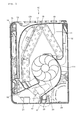
- FIG. 1 is a cross-sectional view illustrating an indoor unit 10 of an air conditioner according to one embodiment.
- the indoor unit 10 of the air conditioner includes a chassis 11, a main body, a base 12, and a front panel 14.
- a front surface of the chassis 11 is provided with a flow guide 111 for generating airflow.
- the main body includes a front frame 13 coupled to a front portion of the chassis 11.
- An intake grill 131 is provided to an upper surface of the front frame 13.
- the base 12 is rotatably coupled to a rear surface of the chassis 11 and fixed to a mounting wall surface.
- the front panel 14 is movably coupled to a front surface of the front frame 13.
- the indoor unit 10 further includes an inner panel 15, a heat exchanger 19, a fan 20, and a discharge grill 16.
- the inner panel 15 is linked to a rear surface of the front panel 14 and rotatably provided to the front frame 13.
- the heat exchanger 19 is disposed between the front frame 13 and the chassis 11.
- the fan 20 is provided to a lower side of the heat exchanger 19 and sucks and discharges indoor air.
- the discharge grill 16 supports a lower end of the heat exchanger 19 and includes a discharge hole.
- the indoor unit 10 further includes a discharge vane 21, a discharge louver 22, a bottom plate 23, and a holder member 24.
- the discharge vane 21 selectively covers the discharge hole.
- the discharge louver 22 is provided to the discharge hole and controls a discharge direction of air, together with the discharge vane 21.
- the bottom plate 23 covers piping passing through a lower end of the indoor unit 10.
- the holder member 24 is rotatably coupled to the chassis 11 and supports the piping.
- the indoor unit 10 further includes a pre-filter 17 and a dust-collecting filter 18.
- the pre-filter 17 filters air sucked through the front surface of the front frame 13 and the intake grill 131.
- the dust-collecting filter 18 is provided between the pre-filter 17 and the heat exchanger 19.
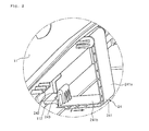
- FIG. 2 is a partial perspective view illustrating a portion A of FIG. 1 .
- the holder member 24 is rotatably coupled to a rear portion of the indoor unit 10.
- a piping work on the indoor unit 10 is performed in a state where the indoor unit 10 is mounted to the wall surface.
- the piping connected to the indoor unit 10 or protruding from the indoor unit 10 to the outside, extends laterally along a bottom surface of the indoor unit 10. At an edge of the indoor unit 10, the piping passes through the bottom surface of the indoor unit 10 to the outside.
- the piping working on the indoor unit 10 may be performed in a state where the lower end of the indoor unit 10 has been rotated from the wall surface to the front side.
- the holder member 24 is rotatably connected to the rear portion of the indoor unit 10, particularly, to a lower end of the chassis 11.
- the holder member 24 includes a holder body 241 bent in an L-shape, an elastic end 242 elastically bendable at an end of the holder body 241, a coupling hook 243 protruding from an outer surface of the elastic end 242, and a pressure surface 244 (refer to FIG. 3 ) pressed by a user's finger.
- the holder body 241 includes a first body 241a and a second body 241b.
- the first body 241a provides a spacing distance between the main body and the wall surface in a state where the main body has been rotated.
- the second body 241b is bent from the first body 241a to stably support the main body against the wall surface in the state where the main body has been rotated.
- the first body 241a is rotatably coupled to the chassis 11, and the second body 241b is removably coupled to the chassis 11.
- the first body 241a extends in the up-and-down direction of the main body, and the second body 241b extends in the back-and-forth direction of the main body.
- the first body 241a extends in the back and forth direction, and the second body 241b extends in the up-and-down direction.
- a coupling rib 112 protrudes from a rear surface of the lower end of the chassis 11 to catch the coupling hook 243.
- the coupling rib 112 is fitted between the coupling hook 243 and the pressure surface 244 (refer to FIG. 3 ), so that the holder member 24 is fixed to the rear lower portion of the indoor unit 10.
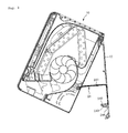
- FIG. 3 is a cross-sectional view illustrating the rotated indoor unit 10 for a piping work, according to an embodiment.
- FIG. 4 is a bottom perspective view illustrating the piping exposed through the rotated indoor unit 10 of FIG. 3 .
- the piping work is performed after raising and rotating the lower end of the indoor unit 10.
- the base 12 of the indoor unit 10 is fixed to the wall surface, and the lower portion of the indoor unit 10 is rotated about the upper end of the base 12 as a rotation center.
- the pressure surface 244 of the holder member 24 is pushed rearward to rotate the holder member 24, so that the holder member 24 is in close contact with the wall surface as illustrated in FIG. 3 .
- a refrigerant piping P and a drain hose H is disposed at the bottom surface of the indoor unit 10 as illustrated in FIG. 4 .
- an outer surface of the refrigerant piping P is wrapped with a heat insulation cover C.
- the lower end of the indoor unit 10 is slightly raised, and then the holder member 24 is rotated forward. After that, the coupling hook 243 of the holder member 24 is caught to the coupling rib 112. Then, the holder member 24 supports the refrigerant piping P and the drain hose H to prevent them from sagging downward.
- the holder member maintains the state where the lower end of the indoor unit is rotated forward from a wall surface.
- the holder member rotates and closely contacts a wall surface, thereby improving workability.
- the holder member supports the indoor unit against the wall surface, so that a user is not required to hold the indoor unit during an installing work, thereby increasing the speed of the installing work.
Landscapes
- Engineering & Computer Science (AREA)
- Chemical & Material Sciences (AREA)
- Combustion & Propulsion (AREA)
- Mechanical Engineering (AREA)
- General Engineering & Computer Science (AREA)
- Physics & Mathematics (AREA)
- Thermal Sciences (AREA)
- Air Filters, Heat-Exchange Apparatuses, And Housings Of Air-Conditioning Units (AREA)
Applications Claiming Priority (1)
| Application Number | Priority Date | Filing Date | Title |
|---|---|---|---|
| KR20080110785 | 2008-11-10 |
Publications (2)
| Publication Number | Publication Date |
|---|---|
| EP2184550A2 true EP2184550A2 (fr) | 2010-05-12 |
| EP2184550A3 EP2184550A3 (fr) | 2011-04-20 |
Family
ID=41527845
Family Applications (1)
| Application Number | Title | Priority Date | Filing Date |
|---|---|---|---|
| EP09250127A Withdrawn EP2184550A3 (fr) | 2008-11-10 | 2009-01-19 | Unité d'intérieur pour climatiseur |
Country Status (2)
| Country | Link |
|---|---|
| EP (1) | EP2184550A3 (fr) |
| CN (1) | CN101737938A (fr) |
Cited By (5)
| Publication number | Priority date | Publication date | Assignee | Title |
|---|---|---|---|---|
| CN102519091A (zh) * | 2011-12-12 | 2012-06-27 | 广东美的制冷设备有限公司 | 一种空调器室内机的安装结构 |
| EP2937642A1 (fr) * | 2014-04-21 | 2015-10-28 | Mitsubishi Electric Corporation | Unité de climatisation |
| JP2017215092A (ja) * | 2016-05-31 | 2017-12-07 | シャープ株式会社 | 空気調和機 |
| WO2020110188A1 (fr) * | 2018-11-27 | 2020-06-04 | 三菱電機株式会社 | Unité intérieure pour un conditionneur d'air |
| CN112032845A (zh) * | 2019-06-04 | 2020-12-04 | 伊莱克斯家用电器股份公司 | 易于触及而进行维护的空调设备及其室内单元与支架 |
Families Citing this family (3)
| Publication number | Priority date | Publication date | Assignee | Title |
|---|---|---|---|---|
| CN102374638A (zh) * | 2010-08-20 | 2012-03-14 | 乐金电子(天津)电器有限公司 | 壁挂式空调器的室内机 |
| KR101579221B1 (ko) | 2013-07-23 | 2015-12-22 | 삼성전자 주식회사 | 공기 조화기의 실내기 및 상기 공기 조화기의 실내기의 냉매관을 연결하는 방법 |
| CN104728928A (zh) * | 2013-12-20 | 2015-06-24 | 广东科龙空调器有限公司 | 空调器室内机 |
Family Cites Families (4)
| Publication number | Priority date | Publication date | Assignee | Title |
|---|---|---|---|---|
| US6990825B2 (en) * | 2000-07-07 | 2006-01-31 | Danfoss A/S | Ventilating device and a building comprising such a ventilating device |
| WO2002103252A2 (fr) * | 2001-06-19 | 2002-12-27 | Lg Electronics Inc. | Climatiseur |
| JP2005024124A (ja) * | 2003-06-30 | 2005-01-27 | Toyotomi Co Ltd | エアコン室内機の設置構造 |
| WO2005040690A1 (fr) * | 2003-10-24 | 2005-05-06 | Lg Electronics Ltd. | Unite interieure de climatiseur |
-
2009
- 2009-01-19 EP EP09250127A patent/EP2184550A3/fr not_active Withdrawn
- 2009-02-13 CN CN200910007208A patent/CN101737938A/zh active Pending
Cited By (6)
| Publication number | Priority date | Publication date | Assignee | Title |
|---|---|---|---|---|
| CN102519091A (zh) * | 2011-12-12 | 2012-06-27 | 广东美的制冷设备有限公司 | 一种空调器室内机的安装结构 |
| CN102519091B (zh) * | 2011-12-12 | 2014-09-03 | 广东美的制冷设备有限公司 | 一种空调器室内机的安装结构 |
| EP2937642A1 (fr) * | 2014-04-21 | 2015-10-28 | Mitsubishi Electric Corporation | Unité de climatisation |
| JP2017215092A (ja) * | 2016-05-31 | 2017-12-07 | シャープ株式会社 | 空気調和機 |
| WO2020110188A1 (fr) * | 2018-11-27 | 2020-06-04 | 三菱電機株式会社 | Unité intérieure pour un conditionneur d'air |
| CN112032845A (zh) * | 2019-06-04 | 2020-12-04 | 伊莱克斯家用电器股份公司 | 易于触及而进行维护的空调设备及其室内单元与支架 |
Also Published As
| Publication number | Publication date |
|---|---|
| CN101737938A (zh) | 2010-06-16 |
| EP2184550A3 (fr) | 2011-04-20 |
Similar Documents
| Publication | Publication Date | Title |
|---|---|---|
| EP2184550A2 (fr) | Unité d'intérieur pour climatiseur | |
| JP4490475B2 (ja) | 空気調和機の室内ユニット | |
| CN101737864B (zh) | 空调的室内机 | |
| EP2184553A1 (fr) | Unité d'intérieur pour climatiseur | |
| US7350370B2 (en) | Air conditioner | |
| EP1816406B1 (fr) | Unité d'intérieur pour climatiseur | |
| EP2184554B1 (fr) | Unité d'intérieur pour climatiseur | |
| CN101772677A (zh) | 空调 | |
| CN101210725B (zh) | 空调的控制器组件 | |
| CN100541020C (zh) | 空调器的室内单元 | |
| KR20100052385A (ko) | 공기 조화기의 실내기 및 실내기의 조립 방법 | |
| EP2184552A1 (fr) | Unité d'intérieur pour climatiseur | |
| EP2095033A2 (fr) | Ensemble de commande d'un climatiseur | |
| CN101581480B (zh) | 空调器的室内机 | |
| KR100548985B1 (ko) | 에어필터의 회동 장착구조를 갖는 에어컨 | |
| KR100347931B1 (ko) | 공기조화기의 공기정화기 장착구조 | |
| KR101101576B1 (ko) | 분리형 공기조화기의 실내기 | |
| CN216307920U (zh) | 一种吸油烟机的面板组件及应用有该面板组件的吸油烟机 | |
| CN100432569C (zh) | 空调机的室内机 | |
| KR20080055018A (ko) | 공기조화기 | |
| KR100792060B1 (ko) | 공기조화기의 연결배관 설치구조 | |
| KR100701930B1 (ko) | 스탠드형 에어컨의 연결배관 정렬구조 | |
| JPH0985032A (ja) | 空気調和機 | |
| KR20080026811A (ko) | 공기조화기 | |
| KR20070077360A (ko) | 분리형 공기조화기의 실내기 |
Legal Events
| Date | Code | Title | Description |
|---|---|---|---|
| PUAI | Public reference made under article 153(3) epc to a published international application that has entered the european phase |
Free format text: ORIGINAL CODE: 0009012 |
|
| AK | Designated contracting states |
Kind code of ref document: A2 Designated state(s): AT BE BG CH CY CZ DE DK EE ES FI FR GB GR HR HU IE IS IT LI LT LU LV MC MK MT NL NO PL PT RO SE SI SK TR |
|
| AX | Request for extension of the european patent |
Extension state: AL BA RS |
|
| PUAL | Search report despatched |
Free format text: ORIGINAL CODE: 0009013 |
|
| AK | Designated contracting states |
Kind code of ref document: A3 Designated state(s): AT BE BG CH CY CZ DE DK EE ES FI FR GB GR HR HU IE IS IT LI LT LU LV MC MK MT NL NO PL PT RO SE SI SK TR |
|
| AX | Request for extension of the european patent |
Extension state: AL BA RS |
|
| AKY | No designation fees paid | ||
| REG | Reference to a national code |
Ref country code: DE Ref legal event code: R108 |
|
| REG | Reference to a national code |
Ref country code: DE Ref legal event code: R108 Effective date: 20111228 |
|
| STAA | Information on the status of an ep patent application or granted ep patent |
Free format text: STATUS: THE APPLICATION IS DEEMED TO BE WITHDRAWN |
|
| 18D | Application deemed to be withdrawn |
Effective date: 20111021 |