EP2184559B1 - Appareil de conditionnement d'air - Google Patents
Appareil de conditionnement d'air Download PDFInfo
- Publication number
- EP2184559B1 EP2184559B1 EP08764726.9A EP08764726A EP2184559B1 EP 2184559 B1 EP2184559 B1 EP 2184559B1 EP 08764726 A EP08764726 A EP 08764726A EP 2184559 B1 EP2184559 B1 EP 2184559B1
- Authority
- EP
- European Patent Office
- Prior art keywords
- panel
- shaft
- section
- wind guide
- opened
- Prior art date
- Legal status (The legal status is an assumption and is not a legal conclusion. Google has not performed a legal analysis and makes no representation as to the accuracy of the status listed.)
- Not-in-force
Links
Images







Classifications
-
- F—MECHANICAL ENGINEERING; LIGHTING; HEATING; WEAPONS; BLASTING
- F24—HEATING; RANGES; VENTILATING
- F24F—AIR-CONDITIONING; AIR-HUMIDIFICATION; VENTILATION; USE OF AIR CURRENTS FOR SCREENING
- F24F1/00—Room units for air-conditioning, e.g. separate or self-contained units or units receiving primary air from a central station
- F24F1/0007—Indoor units, e.g. fan coil units
- F24F1/0011—Indoor units, e.g. fan coil units characterised by air outlets
-
- F—MECHANICAL ENGINEERING; LIGHTING; HEATING; WEAPONS; BLASTING
- F24—HEATING; RANGES; VENTILATING
- F24F—AIR-CONDITIONING; AIR-HUMIDIFICATION; VENTILATION; USE OF AIR CURRENTS FOR SCREENING
- F24F1/00—Room units for air-conditioning, e.g. separate or self-contained units or units receiving primary air from a central station
- F24F1/0007—Indoor units, e.g. fan coil units
- F24F1/0043—Indoor units, e.g. fan coil units characterised by mounting arrangements
- F24F1/0057—Indoor units, e.g. fan coil units characterised by mounting arrangements mounted in or on a wall
-
- F—MECHANICAL ENGINEERING; LIGHTING; HEATING; WEAPONS; BLASTING
- F24—HEATING; RANGES; VENTILATING
- F24F—AIR-CONDITIONING; AIR-HUMIDIFICATION; VENTILATION; USE OF AIR CURRENTS FOR SCREENING
- F24F13/00—Details common to, or for air-conditioning, air-humidification, ventilation or use of air currents for screening
- F24F13/08—Air-flow control members, e.g. louvres, grilles, flaps or guide plates
- F24F13/10—Air-flow control members, e.g. louvres, grilles, flaps or guide plates movable, e.g. dampers
- F24F13/14—Air-flow control members, e.g. louvres, grilles, flaps or guide plates movable, e.g. dampers built up of tilting members, e.g. louvre
- F24F13/1426—Air-flow control members, e.g. louvres, grilles, flaps or guide plates movable, e.g. dampers built up of tilting members, e.g. louvre characterised by actuating means
-
- F—MECHANICAL ENGINEERING; LIGHTING; HEATING; WEAPONS; BLASTING
- F24—HEATING; RANGES; VENTILATING
- F24F—AIR-CONDITIONING; AIR-HUMIDIFICATION; VENTILATION; USE OF AIR CURRENTS FOR SCREENING
- F24F13/00—Details common to, or for air-conditioning, air-humidification, ventilation or use of air currents for screening
- F24F13/08—Air-flow control members, e.g. louvres, grilles, flaps or guide plates
- F24F13/10—Air-flow control members, e.g. louvres, grilles, flaps or guide plates movable, e.g. dampers
- F24F13/14—Air-flow control members, e.g. louvres, grilles, flaps or guide plates movable, e.g. dampers built up of tilting members, e.g. louvre
- F24F13/1426—Air-flow control members, e.g. louvres, grilles, flaps or guide plates movable, e.g. dampers built up of tilting members, e.g. louvre characterised by actuating means
- F24F2013/1446—Air-flow control members, e.g. louvres, grilles, flaps or guide plates movable, e.g. dampers built up of tilting members, e.g. louvre characterised by actuating means with gearings
Definitions
- the present invention relates to an air conditioner including in an indoor unit thereof a panel which is opened and closed according to cooling and heating operation.
- a blow-out port is formed in the front surface of a cabinet in an indoor unit of an air conditioner, and warm air or cool air is blown out from the blow-out port.
- a panel for changing the direction of the air blown out from the blow-out port according to cooling and heating operation is provided.
- Patent Document 1 it is described in Patent Document 1 that a first panel for opening and closing a blow-out port, and a second panel arranged side by side with the first panel are provided. By controlling the direction of the two panels, the blow-out air passage connected to the blow-out port is restricted to a predetermined range.
- the first panel is moved forward at the time of cooling operation.
- Patent Document 2 discloses an air conditioner comprising the features of the preamble of claim 1.
- the panel for changing the wind direction is attached to the cabinet via a shaft, so as to be freely attached and detached for maintenance such as cleaning. Meanwhile, cool air is made to flow along the ceiling at the time of cooling operation, so that the whole room can be cooled without the user being directly exposed to the cool air. This requires that the length of the panel in the front and rear direction is increased to increase the length of the air supply passage.
- the panel When the length of the panel is increased in this way, the user can easily reach the panel. As a result, an external force is easily applied to the panel. For example, in the case where the user carelessly grasps the opened panel, or where an object hits the panel during cleaning, and the like, when the panel is configured to be attached via the shaft, the panel may easily come off from the cabinet.
- the panel is moved only at the time of cooling operation.
- the panel is not moved at the time of heating operation and hence does not contribute to the air blowing.
- the gap between the panel and the cabinet is closed by using another member, such as a flap.
- another member is needed, and further a moving mechanism of the member is also needed.
- it is also possible to increase the air blowing capacity.
- an object of the present invention to provide an air conditioner that has a structure in which even when the length of the panel is increased, the panel opened at the time of cooling and heating operation does not easily come off from the cabinet, and that can efficiently utilize the long panel at the time of cooling and heating operation by moving the panel by a simple mechanism.
- the panel When the panel is moved and when the upper shaft is held, the panel is upwardly opened. When the lower shaft is held, the panel is downwardly opened. In this way, the opening direction of the panel is determined according to which of the shafts is held by the regulating section.
- the upper shaft is provided in an upper portion of the panel, and the lower shaft is provided in a lower portion of the panel.
- the regulating section releases the lower shaft, and locks and rotatably holds the upper shaft.
- the regulating section releases the upper shaft, and locks and rotatably holds the lower shaft. Further, when the panel is closed, the regulating section locks the upper and lower shafts.
- the shaft When the panel is opened, one of the shafts is surely held. That is, the shaft is not rotatably received but can be firmly supported in such a manner of being sandwiched and fitted. This makes it possible to prevent the coming-off of the shaft, so as to thereby prevent the panel from coming off from the cabinet. Further, when the panel is closed, the regulating section locks the upper and lower shafts. This makes it possible to prevent the panel from unexpectedly coming off at the stand-by position thereof.
- the regulating section of the opening and closing mechanism includes a pair of upper and lower holding sections which hold the upper and lower shafts of the panel, and a driving section which operates the holding sections.
- the regulating section releases the lower shaft, and also locks and rotatably holds the upper shaft.
- the regulating section releases the upper shaft, and also locks and rotatably holds the lower shaft.
- the driving section may be independently provided so as to correspond to the upper and lower holding sections, respectively.
- the holding section it is foreseen a pair of rotatable hooks.
- the regulating section when the panel is opened and when the opening direction of the panel is changed, the regulating section once closes the panel so as to lock the upper and lower shafts, and then releases the lock of one of the shafts. That is, when the panel is upwardly opened, the panel is once closed and is then downwardly opened. In this way, when the opening direction is changed, the opening direction is changed after both the shafts are surely locked.
- the regulating section as described above includes a pair of upper and lower hooks which respectively hold the upper and lower shafts, a linkage section which mechanically connects the hooks with each other to operate the hooks, and a changing section which regulates the operation of each of the hooks to change the opening direction. Note that the linkage section is operated by the driving section.
- the hook hold the shaft by sandwiching it.
- the upper and lower hooks are simultaneously moved by the linkage section.
- the changing section regulates the movement of one of the hooks, and thereby only the other hook is made operable.
- the changing section regulates the movement of the other hook, so as to thereby determine the movement of each of the hooks according to the opening direction.
- the panel can be upwardly opened.
- the lower hook is regulated and when the upper hook is made movable, the panel can be downwardly opened.
- the upper and lower shafts are provided on each of the left and right sides of the panel.
- the regulating section is arranged on both the left and right sides, and the left and right regulating sections are operated in association with each other.
- the locking and releasing of the shaft are performed with no time lag on the left and right sides of the panel, so that the panel is prevented from being twisted and opened.
- the opening and closing mechanism includes a moving section which brings the panel close to and away from the cabinet.
- the moving section moves the panel in the direction away from the cabinet when the panel is opened. Also, the moving section moves the panel in the direction close to the cabinet when the panel is closed.
- the moving section includes a rod which is moved into and out of the cabinet.
- the panel is rotatably supported by the rod, and the opening and closing mechanism reciprocates the rod at the time when the panel is opened and closed.
- a mechanism which only reciprocates the rod may be adopted as the opening and closing mechanism, and the panel is opened upwardly or downwardly according to the forward movement of the rod.
- the panel is rotated about the upper shaft so as to be upwardly opened, and is rotated about the lower shaft so as to be downwardly opened.
- the opening angle at the time when the panel is upwardly opened is set larger than the opening angle at the time when the panel is downwardly opened. That is, the panel is upwardly opened at the time of heating operation, while the panel is downwardly opened at the time of cooling operation. Thereby, the opening angle of the panel is set large at the time of heating operation.
- the opening angle of the panel is set small, and hence the distal end of the panel is directed toward the ceiling. Thereby, the cool air is blown out toward the ceiling, so that the reaching distance of the cool air is increased.
- the rod is attached closer to the upper shaft of the panel.
- the lengths from the upper and lower shafts to the attaching position are made different from each other.
- the opening angle is made different depending on the opening direction.
- the opening and closing mechanism includes the moving section which brings the panel close to and away from the cabinet by reciprocating the rod.
- the opening and closing mechanism opens the panel in one of the upper and lower directions by moving the rod forward by the moving section while regulating the opening direction of the panel.
- the panel is upwardly opened, while when the lower side of the panel is regulated, the panel is downwardly opened.
- the rod is similarly moved.
- the panel is rotatably supported by the rod, and hence can be opened in any of the directions.
- a left and right pair of the rods are arranged outside the blow-out port in the left and right direction of the cabinet.
- the rod is formed to have a circular cross section.
- the rod is arranged at a position where the air blowing is not hindered. However, depending on the direction of the air blown out in the left and right direction, the air may hit the rod.
- By forming the rod to have the circular cross section it is possible to prevent dew condensation on the rod even when the cool air hits the rod.
- the present invention when the panel which can be opened upwardly and downwardly about the upper and lower shafts thereof is opened, one of the shafts is surely held, so as to thereby make it possible to prevent the panel from unexpectedly coming off from the cabinet even in the case where an external force is applied to the panel. Further, when the panel is closed, both of the shafts are held, so that the panel can be prevented from easily coming off from the cabinet.
- the regulating section which regulates the opening direction of the panel is configured as a mechanism that includes a pair of upper and lower holding sections which hold the upper and lower shafts of the panel, and a driving section which independently operates each of the holding sections. Therefore, it is possible to provide a simple mechanism also as the panel opening and closing mechanism.
- a rod which is simply reciprocated to open and close the panel is used, so that the structure can be simplified as compared with, for example, the structure in which the panel is opened by using a gear. Further, in the case where the panel is directly opened and closed by the gear, gear noise is generated by a load being applied to the gear, so as to become a problem. When the rod is used, such noise problem is not caused.
- the opening angle of the panel can be changed according to the opening direction of the panel by the simple mechanism. For this reason, it is not necessary to change the opening and closing of the panel by controlling a motor, and it is only necessary to simply control the movement of the rod. As a result, the control is also simplified.
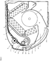
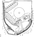
- FIGS 1 and 2 show an indoor unit of an air conditioner according to a present embodiment.
- the indoor unit includes a heat exchanger 1 and an indoor fan 2 which are housed in a cabinet 3.
- the cabinet 3 is formed in a box shape which has a depth greater than its height and which has a curved surface extending from the front surface to the bottom surface.
- a suction port 4 is formed in the upper surface of the cabinet 3, and a blow-out port 5 is formed in the curved surface.
- An air passageway 6 extending from the suction port 4 to the blow-out port 5 is formed in the inside of the cabinet 3, and the heat exchanger 1 and the indoor fan 2 are arranged in the air passageway 6.
- a filter 7 is arranged between the suction port 4 and the heat exchanger 1, so as to remove dust from the indoor air sucked from the suction port 4.
- a cleaning apparatus 8 which cleans the filter 7 is provided.
- the filter 7 is moved by the cleaning apparatus 8 in the cabinet 3 so as to pass through a dust removing section 9. Thereby, the dust adhering to the filter 7 is removed in the dust removing section 9.
- a guide passage 10 curved in a U-shape in side view is formed on the front side in the cabinet 3, and a moving section, which is made of a motor and a gear, reciprocates the filter 7 along the guide passage 10.
- the dust is scraped by a rotating brush 11 from the filter 7 passing through the dust removing section 9.
- a suction fan air is made to flow in the direction substantially in parallel with the filter 7 (in the left and right direction), so that the scraped dust is sucked and discharged.
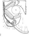
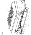
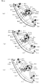
- a wind guide panel 20 which opens and closes the blow-out port 5 is provided on the curved surface of the cabinet 3. As shown in Figures 3 to 6 , the wind guide panel 20 is configured to be able to be upwardly and downwardly opened, and an opening and closing mechanism by which the wind guide panel 20 is moved to be opened and closed is provided.
- the wind guide panel 20 is formed by one curved panel and covers the front surface of the cabinet 3.
- the width of the wind guide panel 20 is set to be the same as the width of the cabinet 3 and is set larger than the width of the blow-out port 5.
- a front panel 21 is formed from the middle stage portion of the front surface to the bottom surface so as to be one stage lower than the front surface.
- a recessed section is formed over the whole width direction so that the wind guide panel 20 can be fit into the recessed section.
- An opening is formed in the front panel 21 which forms the recessed section, and the opening serves as the blow-out port 5. Therefore, the wind guide panel 20 is located in front of the blow-out port 5, so as to cover the blow-out port 5 and the front panel 21 around the blow-out port 5. At this time, the wind guide panel 20 is held in a closed attitude as shown in Figure 2 .
- the outer surface of the wind guide panel 20 forms a smooth curved surface extending from the front surface to the bottom surface of the cabinet 3. That is, the wind guide panel 20 is formed as a member which configures a part of the front surface of the cabinet 3. In other words, a part of the panel of the cabinet 3 is used as the wind guide panel 20. Thereby, the wind guide panel 20 is formed into a long panel having a total length greater than that of the louver adopted in a conventional air conditioner.
- the wind guide panel 20 is rotated about upper and lower shafts in the different directions, so as to thereby be opened in one of the upward and downward directions.
- the wind guide panel 20 is downwardly opened about the lower shaft 22.
- the wind guide panel 20 is connected to the lower wall of the blow-out port 5, so that a long nozzle is formed by the wind guide panel 20 and the upper wall of the blow-out port 5.
- the wind guide panel 20 guides the cool air in the obliquely upward direction so that the cool air is blown out toward the ceiling.
- the wind guide panel 20 is upwardly opened about the upper shaft 23.
- the wind guide panel 20 When held in the upwardly opened attitude, the wind guide panel 20 covers the front of the blow-out port 5 and suppresses the flow of warm air blown out toward the front so as to guide the warm air toward the floor surface. Note that also at the initial stage of the cooling operation, the wind guide panel 20 is held in the upwardly opened attitude to allow the cool air to be blown out toward the floor surface, so that the rapid cooling is performed. As shown in Figure 2 , at the non-operation time, the wind guide panel 20 is held in the closed attitude and covers the blow-out port 5 so as to be integrated with the cabinet 3.
- a wind direction plate 24 and an auxiliary louver are provided in the blow-out port 5.
- the wind direction plate 24 changes its angle in the left and right direction so as to change the wind direction in the left and right direction.
- the auxiliary louver changes the vertical angle thereof according to the attitude of the wind guide panel 20 and thereby changes the vertical wind direction while rectifying the blown-out air.
- a peripheral wall for reinforcement is formed at both side edges on the inner surface of the wind guide panel 20 in the front and rear direction (short side direction).
- the peripheral wall is formed over the whole length in the left and right direction (long side direction).
- the peripheral wall is formed to have a hollow structure and can be thick. With such peripheral wall, the strength of the wind guide panel 20 can be increased, and the deflection of the wind guide panel 20 can be prevented.
- the same peripheral wall for reinforcement is also formed at both side edges in the left and right direction. Therefore, the sway of the wind guide panel 20 can be prevented.
- the strength against deformation of the wind guide panel 20 can be increased, so that the size of the wind guide panel 20 can be increased.
- the wind guide panel 20 is configured to be hardly deformed, and hence the curving degree of the wind guide panel 20 in the front and rear direction can be increased. Thereby, it is possible to easily perform the control of the air blowing direction at the time when the wind guide panel 20 is opened. That is, at the time of cooling operation, cool air can be guided toward the ceiling, so as to increase the reaching distance of the cool air. At the time of heating operation, warm air is guided toward the wall so as to reach the floor surface.
- an inclined surface is formed on the tip side of the peripheral wall.
- the inner side surface of the peripheral wall is formed as the inclined surface.
- the outer side surface of the peripheral wall is formed into a vertical surface.
- a heat insulating material 30 is provided on the inner surface of the wind guide panel 20 surrounded by the peripheral wall.
- the heat insulating material 30 is provided over the whole surface except for both the end sides in the left and right direction.
- the width of the heat insulating material 30 in the left and right direction is set larger than the width of the blow-out port 5.
- the surface of the heat insulating material 30 is formed into one surface. Therefore, there is no projection on the side of the inner surface of the wind guide panel 20, which inner surface faces the blow-out port 5, and hence the air flow cannot be hindered.
- a support 31 is provided on both the left and right sides of the inner surface of the wind guide panel 20.
- the wind guide panel 20 is detachably attached to the support 31.
- the support 31 is attached to the cabinet 3 via a rod 32. That is, the wind guide panel 20 is detachably attached to the cabinet 3 via the rod 32.
- a claw 33 which can be freely slid in the left and right direction is provided on both the left and right sides of the wind guide panel 20.
- the claw 33 faces the peripheral wall formed in the front and rear direction, and is urged by an urging member, such as a spring, toward the peripheral wall.
- the wind guide panel 20 is attached to the support 31 in such a manner that the support 31 is sandwiched between the claw 33 and the peripheral wall.
- the wind guide panel 20 can be removed from the support 31 by sliding the claw 33 in the direction away from the peripheral wall.
- the claw 33 may be provided at least on one side in the front and rear direction.
- a pin is provided in one of the wind guide panel 20 and the support 31, and a hole is formed in the other in which the pin is not provided.
- the wind guide panel 20 is engaged with the support 31 by fitting the pin into the hole.
- the user is able to easily and surely attach and detach the wind guide panel 20 and is also able to perform the attaching and detaching operation while supporting the wind guide panel 20 with a single hand. Thus, it is possible to prevent the falling off of the wind guide panel 20.
- the upper shaft 23 of the wind guide panel 20 is provided on the front side of the support 31, while the lower shaft 22 is provided on the rear side of the support 31.
- the upper and lower shafts 22 and 23 are arranged along the left and right direction, and both ends of the upper and lower shafts 23 and 22 are supported so as to be separated from the support 31.
- the upper and lower shafts 22 and 23 are located on the outside of the blow-out port 5 in the front-and-rear and left-and-right directions, and are located in front of the blow-out port 5. Therefore, the upper and lower shafts 22 and 23 do not impede the flow of the air blown out from the blow-out port 5.
- the support 31 may be integrated with the wind guide panel 20.
- the rod 32 is directly attached to the wind guide panel 20. In this case, when the rod 32 is detachably attached to the wind guide panel 20, the wind guide panel 20 can be detachably attached to the cabinet 3.
- the outdoor unit (not shown) corresponding to the indoor unit is installed in an outdoor location.
- a compressor, a heat exchanger, a four way valve, an outdoor fan, and the like, are incorporated in the outdoor unit, and a refrigerating cycle 40 is formed by these components and the heat exchanger 1 on the indoor side.
- a control apparatus 41 which controls the refrigerating cycle 40 is provided in the indoor unit.
- the control apparatus 41 made of a microcomputer controls the refrigerating cycle 40 to perform cooling and heating operation, on the basis of a user's instruction and detection signals of various sensors 42, such as temperature sensors which detect the room temperature and the outdoor air temperature.
- the control apparatus 41 opens and closes the wind guide panel 20 by controlling an opening and closing mechanism according to the cooling or heating operation.
- the control apparatus 41 cleans the filter 7 by controlling the cleaning apparatus 8 periodically or according to the instruction from the user.
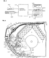
- the opening and closing mechanism is configured, as shown in Figure 7 , by a moving section 50 which brings the wind guide panel 20 close to and away from the cabinet 3, and a regulating section 51 which regulates the opening direction of the wind guide panel 20 at the time when the wind guide panel 20 is moved.
- the moving section 50 moves the wind guide panel 20 in the direction in which the wind guide panel 20 is separated from the cabinet 3.
- the regulating section 51 changes the opening direction of the wind guide panel 20 by allowing one of the upward and downward opening operations of the wind guide panel 20 and by regulating the other opening operation.
- the wind guide panel 20 is upwardly opened.
- the wind guide panel 20 is downwardly opened.
- the regulating section 51 regulates the opening direction by locking one of the upper shaft 23 and the lower shaft 22 to prevent the movement thereof.
- the lower shaft 22 is locked to be rotatably supported, and the upper shaft 23 is released.
- the upper shaft 23 is locked to be rotatably supported, and the lower shaft 22 is released.
- the regulating section 51 has a function to hold the wind guide panel 20 in the closed attitude.
- the wind guide panel 20 in the closed attitude is held close to the front panel 21 of the cabinet 3.
- the regulating section 51 locks the upper shaft 23 and the lower shaft 22. Even when an external force is applied to separate the wind guide panel 20, the wind guide panel 20 is not moved because both the shafts 22 and 23 are locked.
- a driving source only for moving the wind guide panel 20 may be provided as the driving source for opening and closing the wind guide panel 20. Further, the driving source only needs to enable simple operation, such as reciprocating operation of the wind guide panel 20. Therefore, the moving section 50 can be formed into a simple mechanism which reciprocates the wind guide panel 20. Thereby, the opening and closing mechanism can be simplified and miniaturized.
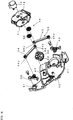
- the regulating section 51 includes a pair of upper and lower hooks 52 and 53 which respectively hold the upper and lower shafts 23 and 22, a changing section 54 which changes the opening direction by regulating the operation of each of the hooks 52 and 53, a linkage section 55 which enables the hooks 52 and 53 to be operated in association with each other, and a driving section 56 which drives the linkage section 55.
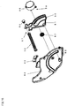
- the moving section 50 includes the rod 32 which holds the wind guide panel 20, a moving mechanism section 57 which moves the rod 32 into and out of the cabinet 3, and a driving section 58 which drives the moving mechanism section 57.
- a left and right pair of the regulating sections 51 are provided in the cabinet 3, and are arranged outside the blow-out port 5 in the left and right direction.
- the regulating section 51 is configured as a unit on a base plate 60.
- the base plate 60 is fixed to the inside of the cabinet 3.
- the upper hook 52 and the lower hook 53 are respectively rotatably supported by fixed shafts 61 fixed to the base plate 60.
- Inlet/outlet ports 21a which respectively allow the hooks 52 and 53 to be projected and retracted are formed in the upper and lower portions of the front panel 21, respectively.
- the upper hook 52 is projected from the inlet/outlet port 21a, so as to hook the upper shaft 23 from the lower side.
- the upper shaft 23 is held by being sandwiched between a receiving base 62 formed in the front panel 21 and the upper hook 52.
- the lower hook 53 is also projected from the inlet/outlet port, so as to hook the lower shaft 22 from the upper side, so that the lower shaft 22 is held by being sandwiched between a receiving base 63 and the lower hook 53.
- the linkage section 55 mechanically connect the hooks 52 and 53 with each other by using a link mechanism, so as to enable each of the hooks 52 and 53 to be operated.
- the linkage section 55 is configured by a pair of upper and lower links 64 and 65, and a linkage plate 66.
- the upper and lower links 64 and 65 connect the upper and lower hooks 52 and 53 to the linkage plate 66, respectively. That is, a shaft 64a is formed at one end of the upper link 64, so as to be fitted into a shaft hole of the upper hook 52.
- the upper hook 52 is rotatably supported at the one end of the upper link 64.
- the lower hook 53 is also similarly supported by the lower link 65.
- the other end of the upper link 64 is rotatably attached to the linkage plate 66.
- the linkage plate 66 is formed into a fan-shaped gear, and gear teeth are formed on the circular arc surface of the linkage plate 66.
- the linkage plate 66 is rotatably supported by a fixed shaft 67 which is projectingly provided on the base plate 60.
- a pair of long grooves 68 are formed in the linkage plate 66, and other end shafts 64b and 65b of the upper and lower links 64 and 65 are fitted into the long grooves 68, respectively.
- Each of the long grooves 68 is extended in the radial direction from the fixed shaft 67 serving as the center.
- the other end shafts 64b and 65b of the links 64 and 65 are respectively made movable in the radial direction, so that a play is provided by each of the long grooves 68.
- the links 64 and 65 are respectively moved in association with each other between the fixed shafts 61 of the hooks 52 and 53 and the fixed shaft 67 of the linkage plate 66. Thereby, the hooks 52 and 53 can be rotated about the fixed shafts 61, respectively.
- the driving section 56 is configured by a plurality of gears 69 and a regulating motor 70.
- the regulating motor 70 is provided on a mounting base 71 attached to the base plate 60.
- the motor shaft of the regulating motor 70 is fitted into the gear 69, so that the driving force of the regulating motor 70 is transmitted to the linkage plate 66 via the plurality of gears 69.
- the linkage plate 66 is rotated about the fixed shaft 67. Therefore, the two hooks 52 and 53 can be moved by one motor.
- the changing section 54 guides the movement of each of the other end shafts 64b and 65b of the links 64 and 65.
- a regulating groove 72 is formed in the mounting base 71, and both the other end shafts 64b and 65b are fitted in the regulating groove 72.
- the movement of each of the hooks 52 and 53 is defined in such a manner that the links 64 and 65 are moved differently from each other by the regulating groove 72. That is, when one of the hooks 52 and 53 is moved, the other of the hooks 52 and 53 is regulated so as not to be moved.
- the changing section 54 defines the movement of the hooks 52 and 53 according to the opening direction.
- the regulating groove 72 is formed approximately in a U-shape.
- the regulating groove 72 is configured by three grooves of an upper locking groove 72a, a neutral groove 72b, and a lower locking groove 72c, and the three grooves are continuously connected.
- the upper locking groove 72a is formed along a circular arc centering on the one end shaft 64a of the upper link 64.
- the lower locking groove 72c is formed along a circular arc centering on the one end shaft 65a of the lower link 65.
- the neutral groove 72b is formed along a circular arc centering on the fixed shaft 67 of the linkage plate 66.
- control apparatus 41 drives the left and right regulating motors 70 so that the above described operations are synchronized with each other in the left and right regulating sections 51.
- a stepping motor is used as the regulating motor 70, so as to be normally and reversely rotated according to the opening direction. Thereby, the wind guide panel 20 is smoothly opened without being twisted at the right and left sides.
- a pair of the moving sections 50 are provided on the left and right sides in the cabinet 3, so as to be arranged outside the regulating sections 51 in the left and right direction, respectively.
- the front end of the rod 32 is made to project to the outside from a vertically long hole 21b (see Figure 3 ) formed in the front panel 21.
- a support shaft 80 for attaching the rod 32 is provided on the support 31.
- the front end of the rod 32 is rotatably supported by the support shaft 80.
- the support shaft 80 is positioned so as to be shifted to the front side from the center in the front and rear direction.
- the rod 32 is formed to have a circular cross section. When the air hits the rod 32, the air is allowed to easily flow.
- the rod 32 is formed to have a hollow structure. Thereby, the weight of the rod 32 can be reduced while the strength of the rod 32 is maintained. As a result, it is possible to reduce the load of the motor to move the rod 32.
- the moving mechanism section 57 moves the front end of the rod 32 to the front side.
- the moving mechanism section 57 moves the front end of the rod 32 to the rear side.
- the moving mechanism section 57 is formed as a moving plate 81 which is reciprocated while holding the rod 32. As shown in Figure 15 , the moving plate 81 is formed into a fan-shape, and is rotatably supported by a fixed shaft 83 which is fixed to a base plate 82.
- the base plate 82 is fixed to the cabinet 3.
- the moving section 50 is also configured as a unit similarly to the regulating section 51.
- the regulating section 51 and the moving section 50 are arranged side by side in each of the spaces respectively provided on both the left and right sides of the cabinet 3.
- both the regulating section 51 and the moving section 50 are configured as one unit, they can be handled as an opening and closing mechanism unit, so as to be easily attached.
- the moving section 50 can be configured by a small number of components, so that the size and thickness of the unit can be reduced.
- the opening and closing mechanism can be housed in a limited space, so that the width of the blow-out port 5 can be increased.
- the blowing range of air in the width direction can be increased, and thereby it is possible to supply the air to all corners of a room.
- the rear end of the rod 32 is rotatably attached to the vicinity of the front end of the moving plate 81 via a rotary shaft 84.
- a circular arc groove 85 is formed in the moving plate 81.
- the circular arc groove 85 is formed on a circular arc centering on the fixed shaft 83.
- a rack is formed in the circular arc groove 85.
- the driving section 58 is configured by an opening and closing motor 86, and a gear 87 attached to the motor shaft of the opening and closing motor 86.
- the gear 87 is inserted into the circular arc groove 85, so as to mesh with the rack.
- the moving plate 81 When the opening and closing motor 86 is driven, the moving plate 81 is rotated about the fixed shaft 83 according to the rotation of the gear 87, so that the rod 32 is moved into and out of the front panel 21.
- the moving plate 81 When the wind guide panel 20 is held in the closed attitude as shown in Figure 11 , the moving plate 81 is located in the rear side. Only the front end of the rod 32 is made to project from the front panel 21. This state is the initial state.
- the moving plate 81 When the lock of the lower shaft 22 is released, and when the opening and closing motor 86 is driven, the moving plate 81 is rotated counterclockwise as shown in Figure 12 .
- the rod 32 is pushed out, so that the front end of the rod 32 is moved to the front side.
- the wind guide panel 20 is rotated about the upper shaft 23, so as to be upwardly opened.
- the opening and closing motor 86 is controlled so that the moving plate 81 is rotated by a fixed angle of, for example, 50 degrees.
- the moving plate 81 When the lock of the upper shaft 23 is released, and when the opening and closing motor 86 is driven, the moving plate 81 is rotated counterclockwise as shown in Figure 13 .
- the rod 32 is pushed out, so that the front end of the rod 32 is moved to the front side.
- the wind guide panel 20 is rotated about the lower shaft 22, so as to be downwardly opened. At this time, the wind guide panel 20 is opened so as to be downwardly moved, and hence the front end of the rod 32 is also moved to the front side while being gradually downwardly moved. Also in this case, the moving plate 81 is rotated by the fixed angle.
- the wind guide panel 20 When the wind guide panel 20 is opened, and when the opening and closing motor 86 is driven to cause the moving plate 81 to rotate clockwise, the wind guide panel 20 is closed. By the rotation of the moving plate 81, the rear end of the rod 32 is moved to the rear side. The rod 32 is drawn into the cabinet 3. Thereby, the wind guide panel 20 is rotated about the upper shaft 23 or the lower shaft 22. The wind guide panel 20 is made to approach the cabinet 3, so as to be held in the closed attitude.
- control apparatus 41 drives the opening and closing motors 86 on the left and right sides so that the above described operations in the left and right side moving sections 50 are synchronized with each other.
- a stepping motor is used as the opening and closing motor 86 and is normally and reversely rotated according to the opening and closing operations.
- one of the upper and lower shafts 22 and 23 of the wind guide panel 20 is locked.
- one of the shafts here, the upper shaft 23
- the upper hook 52 is made to rotate counterclockwise.
- the upper link 64 is pushed in the shaft direction.
- the shaft direction is the direction which connects the one end and the other end of the upper link 64.
- the other end of the upper link 64 pushes the mounting base 71 through the regulating groove 72.
- the direction of the upper locking groove 72a, at which the other end of the upper link 64 is located, is substantially orthogonal to the shaft direction of the upper link 64. Since the mounting base 71 is fixed, the upper link 64 is not moved in the shaft direction. Further, the acting direction of the force from the upper link 64 is substantially orthogonal to the direction of the upper locking groove 72a. No force acts on the other end of the upper link 64 in the direction in parallel with the direction of the upper locking groove 72a. As a result, the upper link 64 is not moved along the upper locking groove 72a, so that the rotation of the upper hook 52 is prevented.
- the upper shaft 23 is firmly held by the upper hook 52. For this reason, even when an external force is applied to the opened wind guide panel 20, the upper shaft 23 is not separated from the upper hook 52.
- the wind guide panel 20 when the wind guide panel 20 is held in the closed attitude, the upper shaft 23 and the lower shaft 22 are locked and held by the hooks 52 and 53, respectively. Therefore, the wind guide panel 20 is not easily separated from the cabinet 3. Further, the wind guide panel 20 in the closed attitude is held as a part of the front panel of the cabinet 3. Thus, the wind guide panel 20 is not hooked by an external object and hence is not unexpectedly separated from the cabinet 3.
- the upper and lower hooks 52 and 53 are mechanically connected to each other so as to be driven by the one motor 70. This prevents the operation timings of the hooks 52 and 53 from being shifted from each other, so that the shafts 22 and 23 can be surely locked and opened. Therefore, the situation in which the lock of the respective shafts 22 and 23 is simultaneously released may not occur, and hence the reliability of opening and closing operation can be improved.
- the opening angle at the time when the wind guide panel 20 is upwardly opened is different from the opening angle at the time when the wind guide panel 20 is downwardly opened.
- the upwardly opening angle is set larger than the downwardly opening angle. That is, the opening angle is increased as the distance from the center to the fulcrum is reduced at the time when the wind guide panel 20 is opened.
- the center is the upper shaft 23 or the lower shaft 22, and the fulcrum is the position of the front end of the rod 32. Since the rod 32 is attached closer to the upper shaft 23, the upwardly opening angle is set large, and the downwardly opening angle is set small.
- the wind guide panel 20 is downwardly opened at the time of cooling operation. However, when the downwardly opening angle is large, the wind guide panel 20 is set below the horizontal line. This causes the cool air to flow in the horizontal direction, and does not cause the air to flow toward the ceiling. The reaching distance of the cool air is reduced, and the cool air directly hits a person. Therefore, in the case where the wind guide panel 20 is downwardly opened, it is preferred to reduce the opening angle.
- the wind guide panel 20 is upwardly opened at the time of heating operation. However, when the opening angle is small, the outlet of the warm air is narrowed. The warm air, which is returned after hitting the wind guide panel 20, has no place to escape, and hence collides with the blown-out warm air, so as to thereby disturb the flow of the warm air. As a result, the velocity of the air blown out toward the floor surface is reduced, so as to prevent the warm air from reaching the floor surface.
- the cooling or heating operation is performed on the basis of an instruction generated when the user operates the remote controller, or is performed when the set time of the timer is reached.
- the control apparatus 41 controls the refrigerating cycle 40 and the opening and closing of the wind guide panel 20. At this time, the control apparatus 41 operates the moving section 50 and the regulating section 51 in association with each other.
- control apparatus 41 When performing the cooling or heating operation, the control apparatus 41 turns on and off the driving of the regulating motor 70 and the opening and closing motor 86 according to a predetermined timing. That is, the respective motors 70 and 86 are sequence-controlled.
- control apparatus 41 performs an initializing operation before the start of operation. That is, the control apparatus 41 determines the position of the wind guide panel 20 at the time when the operation is stopped. When the wind guide panel 20 is not set in the initial state, the control apparatus 41 operates, as the initializing operation, the moving section 50 and the regulating section 51 so that the wind guide panel 20 is set in the initial state. When the operation is started, and when the wind guide panel 20 is set in the initial state, the control apparatus 41 starts the operation without performing the initializing operation. Note that the state in which the wind guide panel 20 is held in the closed attitude is the initial state, and that the opening angle of the wind guide panel 20 is associated with the states of the respective members of the moving section 50 and the regulating section 51.
- a position detecting sensor 90 for detecting the position of the wind guide panel 20 is provided in the moving section 50.
- the position detecting sensors 90 are provided in the left and right moving sections 50, respectively.
- a limit switch is used as the position detecting sensor 90.
- the position detecting sensor 90 is attached to the base plate 82 of the moving section 90 in the cabinet 3.
- the position detecting sensor 90 is arranged so as to be positioned close to the moving plate 81 which is set in the initial state. When the moving plate 81 is set in the initial state, the rod 32 attached to the moving plate 81 is brought into contact with the position detecting sensor 90. Therefore, the position detecting sensor 90 detects that the wind guide panel 20 is set in the initial state, that is, in the closed attitude.
- the position detecting sensor 90 may also be configured to directly detect the position of the wind guide panel 20.
- the position detecting sensor is not limited to the contact type sensor, such as the limit switch, and non-contact type sensors, such as an optical sensor and a camera, may also be used as the position detecting sensor.
- the control apparatus 41 determines whether or not the wind guide panel 20 is set in the initial state.
- the control apparatus 41 determines, on the basis of the detection signal from the position detecting sensor 90, that the wind guide panel 20 is not set in the initial state. Then, the control apparatus 41 performs the initializing operation so as to forcibly set the wind guide panel 20 in the initial state.
- the initialization time period during which the wind guide panel 20 is changed from the fully opened state to the closed state is stored as the initialization time period, and that when the cooling or heating operation is started, the initializing operation of closing the wind guide panel 20 is necessarily performed during the initialization time period, and then the normal operation, such as the cooling or heating operation, is performed.
- the initializing operation even when the wind guide panel 20 is set in the initial state at the time of starting such operation as cooling or heating operation, the initializing operation is necessarily performed during the initialization time period, and hence it takes a time until the operation is shifted to the normal operation of cooling or heating operation.
- the position detecting sensor 90 when the position detecting sensor 90 is provided, it is possible to detect, at the time of starting the operation, whether or not the wind guide panel 20 is set in the initial state. Thus, when the wind guide panel 20 is set in the initial state at the time of starting the operation, it is possible to perform the cooling or heating operation without performing the initializing operation.
- the initializing operation is performed.
- the initializing operation is ended, so that the operation can be shifted to the cooling or heating operation.
- the initializing operation is ended at the time point when the position detecting sensor 90 detects that the wind guide panel 20 is set in the initial state.
- the initializing operation can be shifted to the cooling or heating operation without being performed during the initialization time period.
- the time required for the initializing operation can be reduced by using the detection result from the position detecting sensor 90, so that the initializing operation can be rapidly shifted to the normal operation.
- the opening operation of the wind guide panel 20 is not performed and only the closing operation of the wind guide panel 20 is performed.
- the wind guide panel 20 is once set in the fully opened state (by performing the opening operation for the time period required for shifting the closed state to the fully opened state), and the auxiliary louver is set in the closed state. Thereafter, the wind guide panel 20 is set in the closed state. Even when this operation is performed and when it is not detected by the position detecting sensor 90 that the wind guide panel 20 is set in the initial state, an error display as an operation failure is performed.
- the wind guide panel 20 is first opened to the extent in which at least the auxiliary louver can be rotated (for example, the wind guide panel 20 is fully opened). Then, after the auxiliary louver is closed, the wind guide panel 20 is set in the initial state.
- the moving plate 81 is positioned on the rear side in the moving section 50 as shown in Figure 11 .
- the other end shafts 64b and 65b of the upper and lower links 64 and 65 are located in the neutral groove 72b as shown in Figures 8 and 10(a) .
- the control apparatus 41 first drives the regulating motor 70 of the regulating section 51.
- the linkage plate 66 is rotated clockwise.
- the upper link 64 is rotated about the one end.
- the other end shaft 65b of the lower link 65 is moved along the neutral groove 72b, and thereby the lower link 65 is pulled up.
- the lower hook 53 is rotated clockwise, so that the lock of the lower shaft 22 is released.
- the control apparatus 41 drives the opening and closing motor 86 of the moving section 50 with a slight delay from the timing of starting the regulating motor 70.
- the timing of starting the opening and closing motor 86 is set after the lower hook 53 is separated from the lower shaft 22. That is, the control apparatus 41 stops the regulating motor 70, when a predetermined first timing is reached.
- the first timing is a timing determined according to the time period until the other end shaft 64b of the upper link 64 reaches the end of the upper locking groove 72a as shown in Figure 10(b) . After stopping the regulating motor 70, the control apparatus 41 drives the opening and closing motor 86.
- the opening and closing motor 86 When the opening and closing motor 86 is driven, the moving plate 81 is rotated counterclockwise. The rod 32 is pushed out to the front side, so that the wind guide panel 20 is moved in the direction away from the cabinet 3. The wind guide panel 20 is opened about the upper shaft 23. When the wind guide panel 20 is opened at a set opening angle, the control apparatus 41 stops the opening and closing motor 86. Note that the opening angle is calculated from the number of steps of the opening and closing motor 86.
- the control apparatus 41 drives the opening and closing motor 86 for a fixed time period, and stops the opening and closing motor 86 when a second timing is reached. At this time, the opening angle reaches the maximum opening angle as shown in Figure 12 .
- the wind guide panel 20 is held in the upwardly opened attitude, so that the warm air is blown out toward the floor surface.
- control apparatus 41 controls the regulating motor 70 and the opening and closing motor 86 at the same timing.
- the regulating motor 70 is rotated in the direction opposite to the direction at the time of the heating operation.
- the opening and closing motor 86 is rotated in the same direction as the direction at the time of the heating operation.
- the opening and closing motor 86 When the opening and closing motor 86 is driven for the fixed time period, and when the second timing is reached, the opening and closing motor 86 is stopped. At this time, the opening angle reaches the maximum opening angle as shown in Figure 13 .
- the wind guide panel 20 is held in the downwardly opened attitude, so that the cool air is blown out toward the ceiling.
- the rapid cooling is performed.
- the wind guide panel 20 is first upwardly opened so as to be held in the upwardly opened attitude.
- the wind guide panel 20 is closed so as to be held in the closed attitude, and the upper and lower shafts 22 and 23 are once locked.
- the wind guide panel 20 is downwardly opened so as to be held in the downwardly opened attitude.
- the control apparatus 41 When the cooling or heating operation is ended, the control apparatus 41 first drives the opening and closing motor 86. The rod 32 is pulled back, so that the wind guide panel 20 is made to approach the cabinet 3. The control apparatus 41 stops the opening and closing motor 86 when a predetermined third timing is reached. At this time, as shown in Figure 11 , the wind guide panel 20 is held in the closed attitude, and the moving plate 81 is positioned on the rear side. That is, the third timing is a timing which is determined according to the time when the moving plate 81 is returned to the initial state. Note that the position detecting sensor 90 detects that the moving plate 81 is returned to the initial state. The third timing may also be set according to the detection timing.
- the control apparatus 41 drives the regulating motor 70.
- the state shown in Figure 10(b) is changed to the state shown in Figure 10(a) .
- the lower hook 53 is rotated, so that the lower shaft 22 is locked.
- the control apparatus 41 stops the regulating motor 70 when a predetermined fourth timing is reached.
- the fourth timing is a timing which is determined according to the time period during which the other end shaft 65b of the lower link 65 is moved from the connecting position between the upper locking groove 72a and the neutral groove 72b, to reach the connecting position between the neutral groove 72b and the lower locking groove 72c.
- the above described embodiment exemplifies a structure of the regulating section 51 in which the upper and lower hooks 52 and 53 are mechanically connected to each other so as to be driven by the one regulating motor 70.
- two regulating motors 700a and 700b are provided so as to independently drive the respective hooks 52 and 53.
- the other configuration is the same as that of the above described embodiment.
- the regulating section 51 includes a pair of the upper and lower hooks 52 and 53 which respectively hold the upper and lower shafts 22 and 23, and the regulating motors 700a and 700b as independent driving sections which are respectively connected to the rotary shafts 61a of the hooks 52 and 53.
- the movement of the upper and lower hooks 52 and 53 is the same as that of the first embodiment. That is, the upper hook 52 is projected from the inlet/outlet port 21a (see Figure 5 ), so as to hook the upper shaft 23 from the lower side. The upper shaft 23 is held by being sandwiched between the receiving base 62 formed in the front panel 21 (see Figure 5 ) and the upper hook 52. Similarly, the lower hook 53 is also projected from the inlet/outlet port, so as to hook the lower shaft 22 from the upper side. Thereby, the lower shaft 22 is held by being sandwiched between the lower hook 53 and the receiving base 63 (see Figure 11 and Figure 13 ).
- control apparatus 41 drives the upper hook regulating motor 700a and the lower hook regulating motor 700b which are provided on the left and right sides, in such a manner that the above described operations in the left and right regulating sections 51 are synchronized with each other.
- a stepping motor is used as each of the regulating motors 700a and 700b, so as to be normally and reversely rotated according to the opening direction. Thereby, the wind guide panel 20 is smoothly opened without being twisted at the right and left sides.
- the moving section 50 includes the same mechanism as that shown in Figures 11 to 13 , and hence the explanation thereof is omitted.
- the wind guide panel 20 when the wind guide panel 20 is held in the closed attitude, the upper shaft 23 and the lower shaft 22 are locked and held by the hooks 52 and 53, respectively. Therefore, the wind guide panel 20 is not easily moved from the cabinet 3. Further, the wind guide panel 20 in the closed attitude is held as a part of the front panel of the cabinet 3. Thus, the wind guide panel 20 is not hooked by an external object and hence is not unexpectedly separated from the cabinet 3.
- the regulating section 51 when the wind guide panel 20 is opened, and when the opening direction of the wind guide panel 20 is changed, the regulating section 51 once closes the wind guide panel 20. That is, the regulating motors 700a and 700b are driven by a command from the control apparatus 41. The regulating section 51 operates the upper and lower hooks 52 and 53 so that the upper shaft 23 and the lower shaft 22 are locked by the upper and lower hooks 52 and 53. Then, the regulating section 51 releases the lock of one of the shafts. For example, at the time of starting the cooling operation, the rapid cooling is performed. At this time, the wind guide panel 20 is first upwardly opened so as to be held in the upwardly opened attitude.
- the wind guide panel 20 is closed so as to be held in the closed attitude, and the upper and lower shafts 22 and 23 are once locked. Then, the wind guide panel 20 is downwardly opened so as to be held in the downwardly opened attitude. Thereby, when the opening direction of the opened wind guide panel 20 is changed, at least one of the shafts 22 and 23 is always locked and held. This prevents a state in which both the shafts 22 and 23 are simultaneously released. Thus, it is possible to prevent the coming off of the wind guide panel 20 during opening and closing of the wind guide panel 20.
- the upper hook and the lower hook are provided in the wind guide panel, and the upper shaft and the lower shaft are provided in the cabinet.
- the upper and lower shafts are made movable, and each of the upper and lower hooks is configured as a bearing having an insertion hole for the shaft.
- the wind guide panel is rotatably held by the shaft being inserted into the insertion hole of the hook.
- the upper and lower shafts are fitted into the upper and lower hooks, respectively.
- the wind guide panel is upwardly opened, the upper shaft is held as it is, and the lower shaft is moved so as to be separated from the lower hook.
- the shafts are set in the opposite state.
- a chuck for grasping the upper shaft or the lower shaft may also be used instead of the hook.
- Each of the shafts is locked and held by being grasped by the chuck.
- the lock of each of the shafts is released.
- the portion of the chuck, which portion grasps the shaft is formed into a circular shape, each of the shafts can be rotatably held.
- a rack and pinion may also be used as the moving section.
- the rod is rotatably attached to the rack, and the pinion is driven by the opening and closing motor.
- a cylinder may also be used, and a cylinder rod is expanded and contracted so as to move the wind guide panel.
Landscapes
- Engineering & Computer Science (AREA)
- Chemical & Material Sciences (AREA)
- Combustion & Propulsion (AREA)
- Mechanical Engineering (AREA)
- General Engineering & Computer Science (AREA)
- Air-Flow Control Members (AREA)
- Air Filters, Heat-Exchange Apparatuses, And Housings Of Air-Conditioning Units (AREA)
Claims (16)
- Conditionneur d'air comportant : un orifice de sortie de soufflage (5) formé dans la surface avant d'un boîtier (3), un panneau (20) recouvrant la surface avant ; un arbre supérieur (23) mis en œuvre dans une partie supérieure du panneau (20) et un arbre inférieur (22) mis en œuvre dans une partie inférieure du panneau ; le panneau étant configuré pour être en mesure d'être ouvert vers le haut et vers le bas autour des arbres supérieur et inférieur (22, 23) ; et un mécanisme d'ouverture et de fermeture, au moyen duquel le panneau est déplacé pour être ouvert et fermé en fonction d'un état de fonctionnement, caractérisé en ce que le mécanisme d'ouverture et de fermeture comprend une section de régulation (51) qui régule la direction d'ouverture du panneau (20), et en ce que la section de régulation (51), en retenant l'un des arbres supérieur et inférieur (22, 23), permet l'une parmi une opération d'ouverture vers le haut et une opération d'ouverture vers le bas, et en ce que la section de régulation (51) comprend une paire de sections de retenue supérieure et inférieure servant à retenir les arbres supérieur et inférieur (22, 23) et une section d'entraînement (56) qui actionne les sections de retenue, et en ce que les sections de retenue comprennent un crochet supérieur (52) retenant l'arbre supérieur du panneau (20) et un crochet inférieur (53) retenant l'arbre inférieur (22) du panneau (20), et en ce que, quand le panneau (20) est ouvert vers le haut, le crochet inférieur (53) libère l'arbre inférieur (22), et le crochet supérieur (52) verrouille et retient de manière rotative l'arbre supérieur (23), et, quand le panneau (20) est ouvert vers le bas, le crochet supérieur (52) libère l'arbre supérieur (23) et le crochet inférieur (53) verrouille et retient de manière rotative l'arbre inférieur (22).
- Conditionneur d'air selon la revendication 1, dans lequel la section d'entraînement (56) est mise en œuvre de manière indépendante de manière à correspondre à chacun parmi le crochet supérieur (52) et le crochet inférieur (53).
- Conditionneur d'air selon la revendication 1, dans lequel, quand le panneau (20) est fermé, la section de régulation (51) verrouille l'arbre supérieur (22) au moyen du crochet supérieur (52) et verrouille l'arbre inférieur (23) au moyen du crochet inférieur (53).
- Conditionneur d'air selon la revendication 1, dans lequel, quand le panneau (20) est ouvert et quand la direction d'ouverture du panneau (20) est changée, la section de régulation (51) ferme une fois le panneau (20) pour verrouiller l'arbre supérieur et l'arbre inférieur, et puis libère le verrou de l'un des arbres supérieur et inférieur (22, 23).
- Conditionneur d'air selon la revendication 1, dans lequel la section de régulation comporte une section de liaison (55) qui raccorde mécaniquement les crochets supérieur et inférieur (52, 53) l'un par rapport à l'autre pour actionner les crochets, et une section de changement (54) qui régule le fonctionnement de chacun des crochets pour changer la direction d'ouverture.
- Conditionneur d'air selon la revendication 5, dans lequel, quand l'un des crochets est déplacé, la section de changement (54) régule le mouvement de l'autre crochet, pour de ce fait déterminer le mouvement de chacun des crochets en fonction de la direction d'ouverture.
- Conditionneur d'air selon la revendication 5, dans lequel la section de liaison (55) comprend une plaque de liaison rotative et une paire d'éléments de liaison supérieur et inférieur (64, 65) qui raccordent la plaque de liaison (66) à chacun des crochets (52, 53), et en ce que chacun des éléments de liaison est déplacé en association l'un par rapport à l'autre entre des arbres fixes (61) des crochets (52, 53) et un arbre fixe (67) de la plaque de liaison (66) par la rotation de la plaque de liaison de telle sorte que les crochets respectifs sont déplacés.
- Conditionneur d'air selon la revendication 7, dans lequel l'autre extrémité de l'élément de liaison supérieur (64) et celle de l'élément de liaison inférieur (65) sont attachées de manière rotative à la plaque de liaison (66), dans lequel le crochet supérieur (52) est supporté de manière rotative au niveau de ladite une extrémité de l'élément de liaison supérieur (64), dans lequel le crochet inférieur (53) est supporté de manière rotative au niveau de ladite une extrémité de l'élément de liaison inférieur (65), dans lequel la section de changement guide le mouvement de l'autre extrémité de chacun des éléments de liaison, dans lequel, quand la plaque de liaison (66) est tournée dans le sens des aiguilles d'une montre, ladite une extrémité de l'élément de liaison supérieur (64) n'est pas déplacée et le mouvement du crochet supérieur est régulé, ladite une extrémité de l'élément de liaison inférieur (65) est déplacée et le crochet inférieur (53) est déplacé et le verrou de l'arbre inférieur (22) est libéré, et dans lequel, quand la plaque de liaison (66) est tournée dans le sens inverse des aiguilles d'une montre, ladite une extrémité de l'élément de liaison inférieur (65) n'est pas déplacée et le mouvement du crochet inférieur (53) est régulé alors que ladite une extrémité de l'élément de liaison supérieur (64) est déplacée et le crochet supérieur (52) est déplacé et le verrou de l'arbre supérieur (23) est libéré.
- Conditionneur d'air selon la revendication 1, dans lequel les arbres supérieur et inférieur (22, 23) sont respectivement mis en œuvre sur chacun des côtés gauche et droit du panneau (20) et en ce que la section de régulation (51) est agencée sur les deux côtés gauche et droit de telle sorte que les sections de régulation gauche et droite sont actionnées en association l'une par rapport à l'autre.
- Conditionneur d'air selon la revendication 1, dans lequel le mécanisme d'ouverture et de fermeture comprend une section de déplacement (50) qui déplace le panneau (20) à des fins de rapprochement et d'éloignement du boîtier (3) par un mouvement de va et vient d'une tige (32), en ce que la section de déplacement est configurée, quand le panneau est ouvert, pour déplacer le panneau (20) dans la direction allant en s'éloignant du boîtier (3), et est configurée, quand le panneau (20) est fermé, pour déplacer le panneau (20) dans la direction allant en se rapprochant du boîtier (3), et en ce que le mécanisme d'ouverture et de fermeture ouvre le panneau (20) dans l'une parmi les directions allant vers le haut et allant vers le bas en déplaçant la tige vers l'avant par la section de déplacement (50) tout en régulant la direction d'ouverture du panneau (20).
- Conditionneur d'air selon la revendication 10, dans lequel la tige (32) est mise en œuvre de manière à être déplacée dans et hors du boîtier (3), en ce que la tige (32) supporte de manière rotative le panneau (20) entre les arbres supérieur et inférieur (22, 23), et en ce que le panneau est ouvert vers le haut ou vers le bas par le mécanisme d'ouverture et de fermeture d'une telle manière que la tige (32) est déplacée vers l'avant par la section de déplacement (50) alors que la direction d'ouverture du panneau (20) est régulée par la section de régulation (51).
- Conditionneur d'air selon la revendication 11, dans lequel le panneau (20) tourne autour de l'arbre supérieur (23) de manière à être ouvert vers le haut et tourne autour de l'arbre inférieur (22) de manière à être ouvert vers le bas, et en ce que l'angle d'ouverture au moment où le panneau est ouvert vers le haut est réglé comme étant supérieur par rapport à l'angle d'ouverture au moment où le panneau (20) est ouvert vers le bas.
- Conditionneur d'air selon la revendication 12, dans lequel la tige (32) est attachée plus près de l'arbre supérieur (23) du panneau (20).
- Conditionneur d'air selon la revendication 13, dans lequel la quantité de déplacement de la tige (32) au moment où le panneau est ouvert vers le haut est identique à la quantité de déplacement de la tige (32) au moment où le panneau est ouvert vers le bas.
- Conditionneur d'air selon la revendication 11, dans lequel la section de déplacement (50) comprend une plaque de déplacement (81) qui retient la tige (32) de manière rotative et qui tourne autour d'un arbre, et en ce que, quand la plaque de déplacement est tournée, et quand le verrou de l'arbre inférieur (22) est libéré par la section de régulation, l'extrémité avant de la tige attachée au panneau est déplacée jusque sur le côté avant alors que le panneau est ouvert vers le haut, et quand le verrou de l'arbre supérieur (23) est libéré, la partie avant de la tige est déplacée jusque sur le côté avant progressivement vers le bas alors que le panneau est ouvert vers le bas.
- Conditionneur d'air selon la revendication 15, dans lequel une paire gauche et une paire droite des tiges sont agencées à l'extérieur de l'orifice de sortie de soufflage dans la direction gauche et la direction droite du boîtier (3), et en ce que la tige (32) est formée pour avoir une coupe transversale circulaire.
Applications Claiming Priority (4)
| Application Number | Priority Date | Filing Date | Title |
|---|---|---|---|
| JP2007232698A JP4283322B2 (ja) | 2007-09-07 | 2007-09-07 | 空気調和機 |
| JP2007232690A JP4237238B1 (ja) | 2007-09-07 | 2007-09-07 | 空気調和機 |
| JP2007232717A JP4283323B2 (ja) | 2007-09-07 | 2007-09-07 | 空気調和機 |
| PCT/JP2008/059693 WO2009031343A1 (fr) | 2007-09-07 | 2008-05-27 | Appareil de conditionnement d'air |
Publications (3)
| Publication Number | Publication Date |
|---|---|
| EP2184559A1 EP2184559A1 (fr) | 2010-05-12 |
| EP2184559A4 EP2184559A4 (fr) | 2018-04-11 |
| EP2184559B1 true EP2184559B1 (fr) | 2020-10-21 |
Family
ID=40428667
Family Applications (1)
| Application Number | Title | Priority Date | Filing Date |
|---|---|---|---|
| EP08764726.9A Not-in-force EP2184559B1 (fr) | 2007-09-07 | 2008-05-27 | Appareil de conditionnement d'air |
Country Status (3)
| Country | Link |
|---|---|
| EP (1) | EP2184559B1 (fr) |
| CN (1) | CN101796348B (fr) |
| WO (1) | WO2009031343A1 (fr) |
Families Citing this family (16)
| Publication number | Priority date | Publication date | Assignee | Title |
|---|---|---|---|---|
| EP2796801B1 (fr) * | 2009-11-04 | 2019-01-02 | Daikin Industries, Ltd. | Climatiseur |
| CN102853498B (zh) * | 2011-06-30 | 2016-11-23 | 广东松下环境系统有限公司 | 换气装置 |
| JP5215441B2 (ja) * | 2011-08-29 | 2013-06-19 | シャープ株式会社 | 空気調和機 |
| CN202402369U (zh) | 2011-11-28 | 2012-08-29 | 广东松下环境系统有限公司 | 换气扇 |
| CN105020873B (zh) | 2014-04-24 | 2018-08-07 | 珠海格力电器股份有限公司 | 运动机构、面板机构及家用电器 |
| CN104596075A (zh) * | 2015-01-14 | 2015-05-06 | 广东美的暖通设备有限公司 | 空调室内机的出风面板组件和具有其的空调室内机 |
| CN104566652A (zh) * | 2015-01-16 | 2015-04-29 | 广东美的制冷设备有限公司 | 壁挂式空调器 |
| CN106556064A (zh) * | 2016-10-21 | 2017-04-05 | 珠海格力电器股份有限公司 | 空调器 |
| CN106440308A (zh) * | 2016-10-21 | 2017-02-22 | 珠海格力电器股份有限公司 | 一种空调室内机的封闭式外壳、空调室内机及空调器 |
| CN106482315B (zh) * | 2016-10-21 | 2019-07-23 | 珠海格力电器股份有限公司 | 封闭式空调外壳及具有其的封闭式空调器 |
| CN113007808A (zh) * | 2017-01-25 | 2021-06-22 | 珠海格力电器股份有限公司 | 一种壁挂式空调室内机及空调器 |
| CN109405249B (zh) * | 2018-10-12 | 2021-07-23 | 重庆海尔空调器有限公司 | 一种空调器、用于控制空调器导风的方法 |
| JP7233311B2 (ja) * | 2019-06-11 | 2023-03-06 | シャープ株式会社 | 空気調和機 |
| CN111720887A (zh) * | 2020-06-18 | 2020-09-29 | 海信(山东)空调有限公司 | 空调器室内机 |
| CN115727415B (zh) * | 2021-08-31 | 2024-06-11 | 宁波奥克斯电气股份有限公司 | 一种室内机及空调器 |
| CN216281705U (zh) * | 2021-10-26 | 2022-04-12 | 广东美的制冷设备有限公司 | 空调室内机及空调器 |
Family Cites Families (7)
| Publication number | Priority date | Publication date | Assignee | Title |
|---|---|---|---|---|
| JPH08247491A (ja) * | 1995-03-09 | 1996-09-27 | Fujitsu General Ltd | 空気調和機 |
| JP3669322B2 (ja) * | 2000-11-21 | 2005-07-06 | ダイキン工業株式会社 | 空気調和機の室内機 |
| JP2003074962A (ja) * | 2001-08-28 | 2003-03-12 | Toshiba Kyaria Kk | 空気調和装置 |
| JP4130370B2 (ja) * | 2003-02-28 | 2008-08-06 | 三菱電機株式会社 | エアコン室内機 |
| JP2005315536A (ja) | 2004-04-30 | 2005-11-10 | Fujitsu General Ltd | 空気調和機 |
| JP2007120896A (ja) * | 2005-10-31 | 2007-05-17 | Matsushita Electric Ind Co Ltd | 空気調和機の運転方法 |
| CN2886396Y (zh) * | 2006-03-03 | 2007-04-04 | 广东美的电器股份有限公司 | 一种分体挂壁式空调器室内机 |
-
2008
- 2008-05-27 EP EP08764726.9A patent/EP2184559B1/fr not_active Not-in-force
- 2008-05-27 CN CN2008801058657A patent/CN101796348B/zh active Active
- 2008-05-27 WO PCT/JP2008/059693 patent/WO2009031343A1/fr not_active Ceased
Non-Patent Citations (1)
| Title |
|---|
| None * |
Also Published As
| Publication number | Publication date |
|---|---|
| CN101796348B (zh) | 2013-05-22 |
| WO2009031343A1 (fr) | 2009-03-12 |
| CN101796348A (zh) | 2010-08-04 |
| EP2184559A1 (fr) | 2010-05-12 |
| EP2184559A4 (fr) | 2018-04-11 |
Similar Documents
| Publication | Publication Date | Title |
|---|---|---|
| EP2184559B1 (fr) | Appareil de conditionnement d'air | |
| EP2216608B1 (fr) | Climatiseur | |
| EP2202468B1 (fr) | Appareil de climatisation | |
| EP2226581B1 (fr) | Climatiseur | |
| JP4237238B1 (ja) | 空気調和機 | |
| WO2010021383A1 (fr) | Machine intérieure de climatiseur | |
| JP4950001B2 (ja) | 空気調和機 | |
| JP2009127889A (ja) | 空気調和機 | |
| JP4283323B2 (ja) | 空気調和機 | |
| JP4856045B2 (ja) | 空気調和機 | |
| JP5065442B2 (ja) | 空気調和機 | |
| JP4283322B2 (ja) | 空気調和機 | |
| JP5342026B2 (ja) | 空気調和機 | |
| JP4950100B2 (ja) | 空気調和機 | |
| JP5038092B2 (ja) | 空気調和機 | |
| JP5059661B2 (ja) | 空気調和機 | |
| JP5406319B2 (ja) | 空気調和機 | |
| JP2009063257A (ja) | 空気調和機 | |
| JP2010019497A (ja) | 空気調和機 | |
| JP2008138953A (ja) | 空気調和機 | |
| KR20060087299A (ko) | 에어컨용 오토셔터의 회전봉 보강구조 | |
| KR20070021302A (ko) | 공기 조화기의 실내기 |
Legal Events
| Date | Code | Title | Description |
|---|---|---|---|
| PUAI | Public reference made under article 153(3) epc to a published international application that has entered the european phase |
Free format text: ORIGINAL CODE: 0009012 |
|
| 17P | Request for examination filed |
Effective date: 20100126 |
|
| AK | Designated contracting states |
Kind code of ref document: A1 Designated state(s): AT BE BG CH CY CZ DE DK EE ES FI FR GB GR HR HU IE IS IT LI LT LU LV MC MT NL NO PL PT RO SE SI SK TR |
|
| AX | Request for extension of the european patent |
Extension state: AL BA MK RS |
|
| DAX | Request for extension of the european patent (deleted) | ||
| RA4 | Supplementary search report drawn up and despatched (corrected) |
Effective date: 20180309 |
|
| RIC1 | Information provided on ipc code assigned before grant |
Ipc: F24F 13/14 20060101ALI20180306BHEP Ipc: F24F 13/20 20060101AFI20180306BHEP |
|
| REG | Reference to a national code |
Ref country code: DE Ref legal event code: R079 Ref document number: 602008063379 Country of ref document: DE Free format text: PREVIOUS MAIN CLASS: F24F0013200000 Ipc: F24F0001001100 |
|
| GRAP | Despatch of communication of intention to grant a patent |
Free format text: ORIGINAL CODE: EPIDOSNIGR1 |
|
| STAA | Information on the status of an ep patent application or granted ep patent |
Free format text: STATUS: GRANT OF PATENT IS INTENDED |
|
| INTG | Intention to grant announced |
Effective date: 20200511 |
|
| RIC1 | Information provided on ipc code assigned before grant |
Ipc: F24F 13/14 20060101ALI20200424BHEP Ipc: F24F 1/0011 20190101AFI20200424BHEP Ipc: F24F 13/20 20060101ALI20200424BHEP Ipc: F24F 1/0057 20190101ALI20200424BHEP |
|
| GRAS | Grant fee paid |
Free format text: ORIGINAL CODE: EPIDOSNIGR3 |
|
| GRAA | (expected) grant |
Free format text: ORIGINAL CODE: 0009210 |
|
| STAA | Information on the status of an ep patent application or granted ep patent |
Free format text: STATUS: THE PATENT HAS BEEN GRANTED |
|
| AK | Designated contracting states |
Kind code of ref document: B1 Designated state(s): AT BE BG CH CY CZ DE DK EE ES FI FR GB GR HR HU IE IS IT LI LT LU LV MC MT NL NO PL PT RO SE SI SK TR |
|
| RAP1 | Party data changed (applicant data changed or rights of an application transferred) |
Owner name: SHARP KABUSHIKI KAISHA |
|
| REG | Reference to a national code |
Ref country code: GB Ref legal event code: FG4D |
|
| RIN1 | Information on inventor provided before grant (corrected) |
Inventor name: SETSU, MICHIO Inventor name: OKUNO, TOSHIHARU Inventor name: UEHARA, YUHJI Inventor name: YOSHIKAWA, KAZUYA |
|
| REG | Reference to a national code |
Ref country code: CH Ref legal event code: EP |
|
| REG | Reference to a national code |
Ref country code: DE Ref legal event code: R096 Ref document number: 602008063379 Country of ref document: DE |
|
| REG | Reference to a national code |
Ref country code: IE Ref legal event code: FG4D |
|
| REG | Reference to a national code |
Ref country code: AT Ref legal event code: REF Ref document number: 1326217 Country of ref document: AT Kind code of ref document: T Effective date: 20201115 |
|
| REG | Reference to a national code |
Ref country code: FI Ref legal event code: FGE |
|
| REG | Reference to a national code |
Ref country code: AT Ref legal event code: MK05 Ref document number: 1326217 Country of ref document: AT Kind code of ref document: T Effective date: 20201021 |
|
| REG | Reference to a national code |
Ref country code: NL Ref legal event code: MP Effective date: 20201021 |
|
| PG25 | Lapsed in a contracting state [announced via postgrant information from national office to epo] |
Ref country code: NL Free format text: LAPSE BECAUSE OF FAILURE TO SUBMIT A TRANSLATION OF THE DESCRIPTION OR TO PAY THE FEE WITHIN THE PRESCRIBED TIME-LIMIT Effective date: 20201021 Ref country code: NO Free format text: LAPSE BECAUSE OF FAILURE TO SUBMIT A TRANSLATION OF THE DESCRIPTION OR TO PAY THE FEE WITHIN THE PRESCRIBED TIME-LIMIT Effective date: 20210121 Ref country code: PT Free format text: LAPSE BECAUSE OF FAILURE TO SUBMIT A TRANSLATION OF THE DESCRIPTION OR TO PAY THE FEE WITHIN THE PRESCRIBED TIME-LIMIT Effective date: 20210222 Ref country code: GR Free format text: LAPSE BECAUSE OF FAILURE TO SUBMIT A TRANSLATION OF THE DESCRIPTION OR TO PAY THE FEE WITHIN THE PRESCRIBED TIME-LIMIT Effective date: 20210122 |
|
| REG | Reference to a national code |
Ref country code: LT Ref legal event code: MG4D |
|
| PG25 | Lapsed in a contracting state [announced via postgrant information from national office to epo] |
Ref country code: BG Free format text: LAPSE BECAUSE OF FAILURE TO SUBMIT A TRANSLATION OF THE DESCRIPTION OR TO PAY THE FEE WITHIN THE PRESCRIBED TIME-LIMIT Effective date: 20210121 Ref country code: AT Free format text: LAPSE BECAUSE OF FAILURE TO SUBMIT A TRANSLATION OF THE DESCRIPTION OR TO PAY THE FEE WITHIN THE PRESCRIBED TIME-LIMIT Effective date: 20201021 Ref country code: ES Free format text: LAPSE BECAUSE OF FAILURE TO SUBMIT A TRANSLATION OF THE DESCRIPTION OR TO PAY THE FEE WITHIN THE PRESCRIBED TIME-LIMIT Effective date: 20201021 Ref country code: IS Free format text: LAPSE BECAUSE OF FAILURE TO SUBMIT A TRANSLATION OF THE DESCRIPTION OR TO PAY THE FEE WITHIN THE PRESCRIBED TIME-LIMIT Effective date: 20210221 Ref country code: LV Free format text: LAPSE BECAUSE OF FAILURE TO SUBMIT A TRANSLATION OF THE DESCRIPTION OR TO PAY THE FEE WITHIN THE PRESCRIBED TIME-LIMIT Effective date: 20201021 Ref country code: PL Free format text: LAPSE BECAUSE OF FAILURE TO SUBMIT A TRANSLATION OF THE DESCRIPTION OR TO PAY THE FEE WITHIN THE PRESCRIBED TIME-LIMIT Effective date: 20201021 |
|
| PG25 | Lapsed in a contracting state [announced via postgrant information from national office to epo] |
Ref country code: HR Free format text: LAPSE BECAUSE OF FAILURE TO SUBMIT A TRANSLATION OF THE DESCRIPTION OR TO PAY THE FEE WITHIN THE PRESCRIBED TIME-LIMIT Effective date: 20201021 |
|
| REG | Reference to a national code |
Ref country code: DE Ref legal event code: R097 Ref document number: 602008063379 Country of ref document: DE |
|
| PG25 | Lapsed in a contracting state [announced via postgrant information from national office to epo] |
Ref country code: LT Free format text: LAPSE BECAUSE OF FAILURE TO SUBMIT A TRANSLATION OF THE DESCRIPTION OR TO PAY THE FEE WITHIN THE PRESCRIBED TIME-LIMIT Effective date: 20201021 Ref country code: SK Free format text: LAPSE BECAUSE OF FAILURE TO SUBMIT A TRANSLATION OF THE DESCRIPTION OR TO PAY THE FEE WITHIN THE PRESCRIBED TIME-LIMIT Effective date: 20201021 Ref country code: RO Free format text: LAPSE BECAUSE OF FAILURE TO SUBMIT A TRANSLATION OF THE DESCRIPTION OR TO PAY THE FEE WITHIN THE PRESCRIBED TIME-LIMIT Effective date: 20201021 Ref country code: CZ Free format text: LAPSE BECAUSE OF FAILURE TO SUBMIT A TRANSLATION OF THE DESCRIPTION OR TO PAY THE FEE WITHIN THE PRESCRIBED TIME-LIMIT Effective date: 20201021 Ref country code: EE Free format text: LAPSE BECAUSE OF FAILURE TO SUBMIT A TRANSLATION OF THE DESCRIPTION OR TO PAY THE FEE WITHIN THE PRESCRIBED TIME-LIMIT Effective date: 20201021 |
|
| PLBE | No opposition filed within time limit |
Free format text: ORIGINAL CODE: 0009261 |
|
| STAA | Information on the status of an ep patent application or granted ep patent |
Free format text: STATUS: NO OPPOSITION FILED WITHIN TIME LIMIT |
|
| PG25 | Lapsed in a contracting state [announced via postgrant information from national office to epo] |
Ref country code: DK Free format text: LAPSE BECAUSE OF FAILURE TO SUBMIT A TRANSLATION OF THE DESCRIPTION OR TO PAY THE FEE WITHIN THE PRESCRIBED TIME-LIMIT Effective date: 20201021 |
|
| 26N | No opposition filed |
Effective date: 20210722 |
|
| PG25 | Lapsed in a contracting state [announced via postgrant information from national office to epo] |
Ref country code: IT Free format text: LAPSE BECAUSE OF FAILURE TO SUBMIT A TRANSLATION OF THE DESCRIPTION OR TO PAY THE FEE WITHIN THE PRESCRIBED TIME-LIMIT Effective date: 20201021 |
|
| PG25 | Lapsed in a contracting state [announced via postgrant information from national office to epo] |
Ref country code: SI Free format text: LAPSE BECAUSE OF FAILURE TO SUBMIT A TRANSLATION OF THE DESCRIPTION OR TO PAY THE FEE WITHIN THE PRESCRIBED TIME-LIMIT Effective date: 20201021 |
|
| REG | Reference to a national code |
Ref country code: DE Ref legal event code: R119 Ref document number: 602008063379 Country of ref document: DE |
|
| REG | Reference to a national code |
Ref country code: CH Ref legal event code: PL |
|
| GBPC | Gb: european patent ceased through non-payment of renewal fee |
Effective date: 20210527 |
|
| PG25 | Lapsed in a contracting state [announced via postgrant information from national office to epo] |
Ref country code: LI Free format text: LAPSE BECAUSE OF NON-PAYMENT OF DUE FEES Effective date: 20210531 Ref country code: MC Free format text: LAPSE BECAUSE OF FAILURE TO SUBMIT A TRANSLATION OF THE DESCRIPTION OR TO PAY THE FEE WITHIN THE PRESCRIBED TIME-LIMIT Effective date: 20201021 Ref country code: LU Free format text: LAPSE BECAUSE OF NON-PAYMENT OF DUE FEES Effective date: 20210527 Ref country code: CH Free format text: LAPSE BECAUSE OF NON-PAYMENT OF DUE FEES Effective date: 20210531 |
|
| REG | Reference to a national code |
Ref country code: BE Ref legal event code: MM Effective date: 20210531 |
|
| PG25 | Lapsed in a contracting state [announced via postgrant information from national office to epo] |
Ref country code: IE Free format text: LAPSE BECAUSE OF NON-PAYMENT OF DUE FEES Effective date: 20210527 Ref country code: GB Free format text: LAPSE BECAUSE OF NON-PAYMENT OF DUE FEES Effective date: 20210527 Ref country code: DE Free format text: LAPSE BECAUSE OF NON-PAYMENT OF DUE FEES Effective date: 20211201 |
|
| PG25 | Lapsed in a contracting state [announced via postgrant information from national office to epo] |
Ref country code: IS Free format text: LAPSE BECAUSE OF FAILURE TO SUBMIT A TRANSLATION OF THE DESCRIPTION OR TO PAY THE FEE WITHIN THE PRESCRIBED TIME-LIMIT Effective date: 20210221 Ref country code: FR Free format text: LAPSE BECAUSE OF NON-PAYMENT OF DUE FEES Effective date: 20210531 |
|
| PG25 | Lapsed in a contracting state [announced via postgrant information from national office to epo] |
Ref country code: BE Free format text: LAPSE BECAUSE OF NON-PAYMENT OF DUE FEES Effective date: 20210531 |
|
| PG25 | Lapsed in a contracting state [announced via postgrant information from national office to epo] |
Ref country code: HU Free format text: LAPSE BECAUSE OF FAILURE TO SUBMIT A TRANSLATION OF THE DESCRIPTION OR TO PAY THE FEE WITHIN THE PRESCRIBED TIME-LIMIT; INVALID AB INITIO Effective date: 20080527 Ref country code: CY Free format text: LAPSE BECAUSE OF FAILURE TO SUBMIT A TRANSLATION OF THE DESCRIPTION OR TO PAY THE FEE WITHIN THE PRESCRIBED TIME-LIMIT Effective date: 20201021 |
|
| PGFP | Annual fee paid to national office [announced via postgrant information from national office to epo] |
Ref country code: SE Payment date: 20230519 Year of fee payment: 16 Ref country code: FI Payment date: 20230523 Year of fee payment: 16 |
|
| PG25 | Lapsed in a contracting state [announced via postgrant information from national office to epo] |
Ref country code: MT Free format text: LAPSE BECAUSE OF FAILURE TO SUBMIT A TRANSLATION OF THE DESCRIPTION OR TO PAY THE FEE WITHIN THE PRESCRIBED TIME-LIMIT Effective date: 20201021 |
|
| REG | Reference to a national code |
Ref country code: SE Ref legal event code: EUG |
|
| PG25 | Lapsed in a contracting state [announced via postgrant information from national office to epo] |
Ref country code: FI Free format text: LAPSE BECAUSE OF NON-PAYMENT OF DUE FEES Effective date: 20240527 |
|
| PG25 | Lapsed in a contracting state [announced via postgrant information from national office to epo] |
Ref country code: FI Free format text: LAPSE BECAUSE OF NON-PAYMENT OF DUE FEES Effective date: 20240527 |
|
| PG25 | Lapsed in a contracting state [announced via postgrant information from national office to epo] |
Ref country code: SE Free format text: LAPSE BECAUSE OF NON-PAYMENT OF DUE FEES Effective date: 20240528 |
|
| PG25 | Lapsed in a contracting state [announced via postgrant information from national office to epo] |
Ref country code: TR Free format text: LAPSE BECAUSE OF FAILURE TO SUBMIT A TRANSLATION OF THE DESCRIPTION OR TO PAY THE FEE WITHIN THE PRESCRIBED TIME-LIMIT Effective date: 20201021 |