EP2184571B1 - Réfrigérateur - Google Patents
Réfrigérateur Download PDFInfo
- Publication number
- EP2184571B1 EP2184571B1 EP09169195.6A EP09169195A EP2184571B1 EP 2184571 B1 EP2184571 B1 EP 2184571B1 EP 09169195 A EP09169195 A EP 09169195A EP 2184571 B1 EP2184571 B1 EP 2184571B1
- Authority
- EP
- European Patent Office
- Prior art keywords
- control unit
- door
- refrigerator
- cover
- installation hole
- Prior art date
- Legal status (The legal status is an assumption and is not a legal conclusion. Google has not performed a legal analysis and makes no representation as to the accuracy of the status listed.)
- Active
Links
Images


Classifications
-
- F—MECHANICAL ENGINEERING; LIGHTING; HEATING; WEAPONS; BLASTING
- F25—REFRIGERATION OR COOLING; COMBINED HEATING AND REFRIGERATION SYSTEMS; HEAT PUMP SYSTEMS; MANUFACTURE OR STORAGE OF ICE; LIQUEFACTION SOLIDIFICATION OF GASES
- F25D—REFRIGERATORS; COLD ROOMS; ICE-BOXES; COOLING OR FREEZING APPARATUS NOT OTHERWISE PROVIDED FOR
- F25D29/00—Arrangement or mounting of control or safety devices
- F25D29/005—Mounting of control devices
-
- F—MECHANICAL ENGINEERING; LIGHTING; HEATING; WEAPONS; BLASTING
- F25—REFRIGERATION OR COOLING; COMBINED HEATING AND REFRIGERATION SYSTEMS; HEAT PUMP SYSTEMS; MANUFACTURE OR STORAGE OF ICE; LIQUEFACTION SOLIDIFICATION OF GASES
- F25D—REFRIGERATORS; COLD ROOMS; ICE-BOXES; COOLING OR FREEZING APPARATUS NOT OTHERWISE PROVIDED FOR
- F25D23/00—General constructional features
- F25D23/02—Doors; Covers
- F25D23/028—Details
-
- F—MECHANICAL ENGINEERING; LIGHTING; HEATING; WEAPONS; BLASTING
- F25—REFRIGERATION OR COOLING; COMBINED HEATING AND REFRIGERATION SYSTEMS; HEAT PUMP SYSTEMS; MANUFACTURE OR STORAGE OF ICE; LIQUEFACTION SOLIDIFICATION OF GASES
- F25D—REFRIGERATORS; COLD ROOMS; ICE-BOXES; COOLING OR FREEZING APPARATUS NOT OTHERWISE PROVIDED FOR
- F25D29/00—Arrangement or mounting of control or safety devices
-
- F—MECHANICAL ENGINEERING; LIGHTING; HEATING; WEAPONS; BLASTING
- F25—REFRIGERATION OR COOLING; COMBINED HEATING AND REFRIGERATION SYSTEMS; HEAT PUMP SYSTEMS; MANUFACTURE OR STORAGE OF ICE; LIQUEFACTION SOLIDIFICATION OF GASES
- F25D—REFRIGERATORS; COLD ROOMS; ICE-BOXES; COOLING OR FREEZING APPARATUS NOT OTHERWISE PROVIDED FOR
- F25D2323/00—General constructional features not provided for in other groups of this subclass
- F25D2323/02—Details of doors or covers not otherwise covered
- F25D2323/023—Door in door constructions
-
- F—MECHANICAL ENGINEERING; LIGHTING; HEATING; WEAPONS; BLASTING
- F25—REFRIGERATION OR COOLING; COMBINED HEATING AND REFRIGERATION SYSTEMS; HEAT PUMP SYSTEMS; MANUFACTURE OR STORAGE OF ICE; LIQUEFACTION SOLIDIFICATION OF GASES
- F25D—REFRIGERATORS; COLD ROOMS; ICE-BOXES; COOLING OR FREEZING APPARATUS NOT OTHERWISE PROVIDED FOR
- F25D2400/00—General features of, or devices for refrigerators, cold rooms, ice-boxes, or for cooling or freezing apparatus not covered by any other subclass
- F25D2400/06—Refrigerators with a vertical mullion
-
- F—MECHANICAL ENGINEERING; LIGHTING; HEATING; WEAPONS; BLASTING
- F25—REFRIGERATION OR COOLING; COMBINED HEATING AND REFRIGERATION SYSTEMS; HEAT PUMP SYSTEMS; MANUFACTURE OR STORAGE OF ICE; LIQUEFACTION SOLIDIFICATION OF GASES
- F25D—REFRIGERATORS; COLD ROOMS; ICE-BOXES; COOLING OR FREEZING APPARATUS NOT OTHERWISE PROVIDED FOR
- F25D2400/00—General features of, or devices for refrigerators, cold rooms, ice-boxes, or for cooling or freezing apparatus not covered by any other subclass
- F25D2400/36—Visual displays
- F25D2400/361—Interactive visual displays
Definitions
- the present invention relates to a refrigerator, and more particularly to a refrigerator with a control unit to select an operation of the refrigerator.
- a refrigerator is an apparatus, which includes constituent elements of a refrigerating cycle, and stores objects in a cold state or a frozen state with cold air generated through the constituent elements of the refrigerating cycle.
- the refrigerator includes a main body forming storage chambers, such as a freezing chamber and a refrigerating chamber, and doors to open and close the storage chambers.
- a display unit to display the operating state of the refrigerator and a control unit including buttons to allow a user to select an operation of the refrigerator are installed on the front surface of one of the doors.
- an installation part at which the control unit is installed, is provided on the front surface of the door, and the control unit is fixed to the installation part through connection members, such as screws. Then a cover having an area large enough to cover the installation part exposed through the circumference of the control unit is installed on the installation part.
- the boundary between the control unit and the cover invariably forms a line, and thus the design of the front surface of the door is restricted by the control unit and it is difficult to obtain different designs of the door.
- the cover installed on the installation part must to have a larger size than that of the control unit such that the cover can sufficiently cover the circumference of the control unit, and thus the production cost of the door is increased.
- JP-A-2001153538 discloses a door of a refrigerator.
- a kind of control unit comprises an indicator and a number of switches.
- JP 2000088445 A discloses a container for containing a display unit and is directed to a door of a refrigerator. For the receipt of a control unit, a reception part is provided in the door and also a kind of installation hole.
- DE 19505830 A1 discloses a refrigerator with a main body, doors and storage chambers. At a lower end of an upper door, a control unit is installed in the door.
- the refrigerator may further include a cover installed at the installation hole to close the installation hole. Switches to select the operation and display units to display an operating state of the refrigerator may be provided on the front surface of the control unit.
- One side end of the door may be rotatably installed on the main body; and the installation hole may be provided on the other side end of the door.
- a handle groove may be provided on the cover.
- the refrigerator may further include guide parts provided on the rear surface of the reception part and slantingly protruded toward the front portion of one side part of the door to guide the control unit forward.
- a pair of hooks latched into the installation hole to maintain the installation state of the cover in the installation hole may be formed at both sides of the cover.
- First support protrusions to support the side surfaces of the control unit and second support protrusions to support the rear surface of the control unit may be provided on the cover.
- the cover may be installed at the lower end of a connection part extended downwardly from the lower end of the control unit, and thus move together with the control unit and be inserted into the installation hole.
- a first elastic support part protruding forward to elastically support the control unit forward may be provided on the rear surface of the reception part.
- a second elastic support part protruding backward to elastically support the rear surface of the control unit may be provided on the cover.
- the refrigerator in accordance with this embodiment includes a main body 10 forming the external appearance of the refrigerator and provided with storage chambers 11R and 11F, front surfaces of which are opened to store objects therein, and doors 20R and 20F, side ends of which are rotatably installed at one side end of the main body 10 to open and close the storage chambers 11R and 11F.
- the storage chambers 11R and 11F include a refrigerating chamber 11R to store objects in a cold state and a freezing chamber 11F to store objects in a frozen state
- the doors 20R and 20F include a refrigerating chamber door 20R to open and close the refrigerating chamber 11R and a freezing chamber door 20F to open and close the freezing chamber 11F.
- a compressor 12 to compress a refrigerant is installed in the lower region of the rear portion of the main body 10.
- a refrigerating chamber evaporator 13R and a freezing chamber evaporator 13F to generate cold air are installed in the rear of the refrigerating chamber 11R and freezing chamber 11F, respectively.
- a refrigerating chamber air flower fan 14R and a freezing chamber air flower fan 14F to generate suction force and blowing force to circulate the cold air generated from the refrigerating chamber evaporator 13R and the freezing chamber evaporator 13F into the refrigerating chamber 11R and the freezing chamber 11F are also respectively installed at the rear portions of the refrigerating chamber 11R and the freezing chamber 11F.
- a plurality of racks 15 to effectively divisionally store many objects is disposed in the refrigerating chamber 11R and the freezing chamber 11F, and a plurality of door racks 21 to store cans or drink bottles are disposed on the inner surfaces of the refrigerating chamber door 20R and the freezing chamber door 20F.
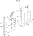
- a control unit 30 to allow a user to select an operation of the refrigerator is installed in the refrigerating chamber door 20R. As shown in FIGS. 3 and 4 , a plurality of display units 31 to display a temperature or a selected operating state and a plurality of switches 32 to allow the user to select the operation of the refrigerator are disposed on the front surface of the control unit 30, and thus the user selects the operation of the refrigerator through the switches 32 of the control unit 30 and confirms the operating state through the display units 31 of the control unit 30.
- the front surface of the refrigerating chamber door 20R is made of a transparent member 22, such as tempered glass, in consideration of the aesthetic appearance of the refrigerator
- a transparent window part 22a to show the display units 31 to the outside of the refrigerating chamber door 20R is formed at a position of the transparent member 22 corresponding to the display units 31 of the control unit 30 installed in a reception part 20a of the refrigerating chamber door 20R.
- the control unit 30 is installed such that the front surface of the control unit 30 contacts the inner surface of the transparent member 22 forming the front surface of the refrigerating chamber door 20R, and the switches 32 of the control unit 30 are electrostatic switches, which sense static electricity. Therefore, when a user's hand contacts a region of the transparent member 22 corresponding to the position of one of the switches 32, static electricity is transferred to the switch 32 due to the contact of the user's hand with the transparent member 22, and thus the switch 32 is operated in a touch mode.
- the reception part 20a in which the control unit 30 is received
- an installation hole 20b through which the control unit 30 is received in the reception part 20a, are provided in the refrigerating chamber door 20R.
- a cover 40 to close the installation hole 20b is installed at the installation hole 20b.
- the installation hole 20b is provided in the other side end of the refrigerating chamber door 20R, one side end of which is rotatably installed at the main body 10.
- Guide parts 23, which are slantingly protruded toward the front portion of one side part of the refrigerating chamber door 20R to guide the control unit 30, coming into the reception part 20a through the installation hole 20b, forward, are formed on the rear surface of the reception part 20a. Therefore, the front surface of the control unit 30 contacts the rear surface of the transparent member 22 through the guide parts 23.
- a handle groove 40a to cause a user to easily grip the refrigerating chamber door 20R is dented into the cover 40, and thus the cover 40 serves as a handle of the refrigerating chamber door 20R.
- Hooks 41 to maintain the installation state of the cover in the installation hole 20b are respectively formed at the upper and lower ends of the cover 40.
- first support protrusions 42 to support the side surfaces of the control unit 30 installed in the reception part 20a and second support protrusions 43 to support the rear surface of the control unit 30 are formed on the inner surface of the cover 40.
- control unit 30 is installed in the reception part 20a under the condition that one side end of the control unit 30 is supported by the guide parts 23, the other side end of the control unit 30 is supported by the first support protrusions 42 and the second protrusions 43, and thus the front surface of the control unit 30 contacts the transparent member 22 forming the front surface of the refrigerating chamber door 20R.
- the installation hole 20b and the cover 40 When the installation hole 20b is formed on one side end of the refrigerating chamber door 20R, as described above, the installation hole 20b and the cover 40 have a small area corresponding to the area of the side end of the control unit 30, and thus the amount of a material for the cover 40 is reduced. Further, the installation hole 20b and the cover 40 located at the side end of the refrigerating chamber door 20R cannot be seen by a user generally located in front of the refrigerator, and thus it is possible to prevent the lowering of the external appearance of the refrigerator by the installation hole 20b and the cover 40.
- the installation hole 20b which is provided on the other side end of the refrigerating chamber door 20R, one side end of which is rotatably installed at the main body 10
- the installation hole 20b may be provided on any one of both side ends, an upper end, and a lower end of the refrigerating chamber door 20R or the freezing chamber door 20F.
- the refrigerator in accordance with this example includes a sub storage chamber 20C formed in the refrigerating chamber door 20R'. This allows stored objects to be taken out without opening a refrigerating chamber door 20R', and a sub door 50 to open and close the sub storage chamber 20C.
- a control unit 30' is installed above the sub storage chamber 20C, and a reception part 20a', in which the control unit 30' is received, and an installation hole 20b', through which the control unit 30' is received in the reception part 20a', are provided in the refrigerating chamber door 20R'.
- a cover 40' to close the installation hole 20b' is installed at the installation hole 20b'.
- the installation hole 20b' is provided in the upper surface of the sub storage chamber 20C.
- a connection part 33 extended downwardly from the control unit 30' is connected to the cover 40', and allows the cover 40' and the control unit 30' to move together and to be installed in the installation hole 20b'.
- Hooks 41' to maintain the installation state of the cover 40' in the installation hole 20b' are respectively formed at both sides the cover 40'.
- a second elastic support part 44 which is protruded backward from the cover 40 and is supported by the rear surface of the reception part 20a', is provided on the cover 40'.
- control unit 30' is installed in the reception part 20a' under the condition that the upper portion of the control unit 30' is supported by the guide parts 23' and the first elastic support part 24, the lower portion of the control unit 30' is supported by the second elastic support part 44, and thus the front surface of the control unit 30' contacts the transparent member 22 forming the front surface of the refrigerating chamber door 20R'.
- the installation hole 20b' is formed through the upper surface of the sub storage chamber 20c, as described above, the installation hole 20b' and the cover 40' cannot be seen by a user of the refrigerator. Particularly, when the sub storage chamber 20c is closed by the sub door 50, the installation hole 20b' and the cover 40' are covered up by the sub door 50 and thus are completely unseen.
- the control unit is installed through the side end of the door, which is deviated from a user's sight, and thus does not influence the front design of the door, thereby achieving various front designs of the door.
- the installation hole has a small area corresponding to that of the side surface of the control unit, and the installation hole and the cover are not seen from an area in front of the refrigerator, thereby further enhancing the external appearance of the refrigerator.
Landscapes
- Engineering & Computer Science (AREA)
- Chemical & Material Sciences (AREA)
- Combustion & Propulsion (AREA)
- Physics & Mathematics (AREA)
- Mechanical Engineering (AREA)
- Thermal Sciences (AREA)
- General Engineering & Computer Science (AREA)
- Refrigerator Housings (AREA)
- Cold Air Circulating Systems And Constructional Details In Refrigerators (AREA)
- Devices That Are Associated With Refrigeration Equipment (AREA)
Claims (10)
- Réfrigérateur comprenant:un corps principal (10) muni de compartiments de rangement (11R, 11F);des portes (20R, 20F, 20R', 20F', 20F') pour ouvrir et fermer respectivement les compartiments de rangement (11R, 11F);une unité de commande (30, 30') installée dans une porte à l'extérieur des portes pour sélectionner une opération;une partie réception (20a, 20a') prévue dans ladite porte pour recevoir l'unité de commande;un trou d'installation (20b, 20b') formé sur une extrémité latérale de la porte pour amener l'unité de commande dans la partie réception, et des unités d'affichage (31) prévues sur une surface frontale de l'unité de commande (30, 30') pour afficher un état de fonctionnement du réfrigérateur,caractérisé en ce que le réfrigérateur comprend en outre:un élément transparent (22) installé devant la porte (20F) pour former une surface avant de la porte,une partie de fenêtre transparente (22a) prévue à une position de l'élément transparent correspondant aux unités d'affichage (31) pour montrer les unités d'affichage (31) à l'extérieur de la porte, et des commutateurs (32) pour sélectionner l'état de fonctionnement du réfrigérateur prévu sur la surface frontale de l'unité de commande,dans laquelle les interrupteurs comprennent des interrupteurs électrostatiques fonctionnant à l'électricité statique.
- Réfrigérateur selon la revendication 1, comprenant en outre un couvercle (40, 40') installé dans le trou d'installation pour fermer le trou d'installation (20b, 20b').
- Réfrigérateur selon la revendication 1, dans lequel:une extrémité latérale de la porte (20R) est installée rotative sur le corps principal (10); etle trou d'installation (20b) est prévu sur l'autre extrémité latérale de la porte.
- Réfrigérateur selon la revendication 2, dans lequel une rainure de poignée (40a) est prévue sur le couvercle (40).
- Réfrigérateur selon la revendication 1, comprenant en outre des parties de guidage (23) prévues sur la surface arrière de la partie réception (20a) et faisant saillie en biais vers la partie avant d'une partie latérale de la porte pour guider l'unité de commande (30) en avant.
- Réfrigérateur selon la revendication 2, dans lequel une paire de crochets (41) fixés dans le trou de montage (20b) pour maintenir l'état de montage du couvercle dans le trou de montage est formée des deux côtés du couvercle.
- Réfrigérateur selon la revendication 2, dans lequel des premières saillies de support (42) pour supporter les surfaces latérales de l'unité de commande (30) et des secondes saillies de support (43) pour supporter la surface arrière de l'unité de commande (30) sont prévues sur le couvercle (40).
- Réfrigérateur selon la revendication 7, dans lequel le couvercle (40) est monté à l'extrémité inférieure d'une partie de connexion (33) s'étendant vers le bas à partir de l'extrémité inférieure de l'unité de commande (30), et se déplace ainsi avec l'unité de commande et est inséré dans le trou de montage (20b).
- Réfrigérateur selon la revendication 1, dans lequel une première partie de support élastique (24) faisant saillie vers l'avant pour supporter élastiquement l'unité de commande (30') vers l'avant est prévue sur la surface arrière de la partie réception (20a').
- Réfrigérateur selon la revendication 9, dans lequel une deuxième partie de support élastique (44) faisant saillie vers l'arrière pour supporter élastiquement la surface arrière de l'unité de commande (30') est prévue sur le couvercle (40').
Applications Claiming Priority (1)
| Application Number | Priority Date | Filing Date | Title |
|---|---|---|---|
| KR1020080109358A KR101602431B1 (ko) | 2008-11-05 | 2008-11-05 | 냉장고 |
Publications (3)
| Publication Number | Publication Date |
|---|---|
| EP2184571A2 EP2184571A2 (fr) | 2010-05-12 |
| EP2184571A3 EP2184571A3 (fr) | 2017-12-20 |
| EP2184571B1 true EP2184571B1 (fr) | 2019-12-25 |
Family
ID=41630988
Family Applications (1)
| Application Number | Title | Priority Date | Filing Date |
|---|---|---|---|
| EP09169195.6A Active EP2184571B1 (fr) | 2008-11-05 | 2009-09-02 | Réfrigérateur |
Country Status (3)
| Country | Link |
|---|---|
| US (3) | US8485617B2 (fr) |
| EP (1) | EP2184571B1 (fr) |
| KR (1) | KR101602431B1 (fr) |
Cited By (1)
| Publication number | Priority date | Publication date | Assignee | Title |
|---|---|---|---|---|
| US11852403B2 (en) | 2016-01-05 | 2023-12-26 | Lg Electronics Inc. | Refrigerator having panel assembly |
Families Citing this family (79)
| Publication number | Priority date | Publication date | Assignee | Title |
|---|---|---|---|---|
| KR20100122155A (ko) * | 2009-05-12 | 2010-11-22 | 엘지전자 주식회사 | 냉장고 |
| KR101307735B1 (ko) * | 2009-06-03 | 2013-09-11 | 엘지전자 주식회사 | 냉장고 |
| CN102116554A (zh) | 2010-01-04 | 2011-07-06 | Lg电子株式会社 | 电冰箱 |
| CN102472558B (zh) * | 2010-02-01 | 2014-07-30 | Lg电子株式会社 | 冰箱 |
| CA2760815A1 (fr) | 2010-02-01 | 2011-08-04 | Lg Electronics Inc. | Refrigerateur et son procede de commande |
| EP2585775B1 (fr) | 2010-06-22 | 2021-08-11 | LG Electronics Inc. | Réfrigérateur et son procédé de fabrication |
| KR101249495B1 (ko) * | 2010-07-19 | 2013-04-01 | 위니아만도 주식회사 | 디스플레이패널유닛 장착장치 |
| KR101704817B1 (ko) | 2010-08-20 | 2017-02-08 | 엘지전자 주식회사 | 냉장고 |
| TR201102179A2 (tr) | 2011-03-07 | 2012-01-23 | Vestel Beyaz Eşya Sanayi̇ Ve Ti̇caret Anoni̇m Şi̇rketi̇@ | Soğutucu cihazlar için bir panel. |
| KR20120116207A (ko) | 2011-04-12 | 2012-10-22 | 엘지전자 주식회사 | 디스플레이 장치 및 이를 구비하는 냉장고 |
| CN103477170B (zh) | 2011-08-05 | 2016-03-16 | Lg电子株式会社 | 具有内部门的冰箱 |
| KR101325445B1 (ko) * | 2011-08-23 | 2013-11-04 | 위니아만도 주식회사 | 냉장고의 디스플레이 손잡이 구조 |
| DE102011088653A1 (de) | 2011-12-15 | 2013-06-20 | BSH Bosch und Siemens Hausgeräte GmbH | Bedienfeld für ein Elektrogerät |
| DE102012200810A1 (de) | 2012-01-20 | 2013-07-25 | BSH Bosch und Siemens Hausgeräte GmbH | Kältegerät mit in der Tür angeordneter Benutzerschnittstelle |
| JP5992782B2 (ja) * | 2012-09-12 | 2016-09-14 | シャープ株式会社 | 冷蔵庫 |
| JP5989485B2 (ja) * | 2012-09-26 | 2016-09-07 | シャープ株式会社 | 冷蔵庫 |
| KR102009947B1 (ko) * | 2013-01-02 | 2019-08-12 | 엘지전자 주식회사 | 가전기기 |
| DE102012220283B4 (de) | 2012-11-07 | 2023-12-14 | BSH Hausgeräte GmbH | Kältegerät mit einer Eisausgabe oder einer Wasserausgabe |
| US8960934B2 (en) * | 2013-04-08 | 2015-02-24 | Samsung Electronics Co., Ltd. | Refrigerator and method of manufacturing the same |
| CN203687503U (zh) * | 2013-08-29 | 2014-07-02 | 博西华电器(江苏)有限公司 | 用于冰箱的门以及冰箱 |
| JP6571911B2 (ja) * | 2013-10-22 | 2019-09-04 | 東芝ライフスタイル株式会社 | 冷蔵庫扉 |
| JP6118712B2 (ja) * | 2013-11-12 | 2017-04-19 | 日立アプライアンス株式会社 | 冷蔵庫 |
| KR20150081800A (ko) * | 2014-01-07 | 2015-07-15 | 삼성전자주식회사 | 냉장고 및 그 제조 방법 |
| CN105276901A (zh) * | 2014-06-12 | 2016-01-27 | 博西华电器(江苏)有限公司 | 家用电器 |
| CN105222502B (zh) * | 2014-06-12 | 2022-07-22 | 博西华电器(江苏)有限公司 | 家用电器 |
| CN105333679B (zh) * | 2014-07-18 | 2019-03-22 | 博西华电器(江苏)有限公司 | 冰箱 |
| CN105258437B (zh) * | 2014-07-18 | 2019-02-26 | 博西华电器(江苏)有限公司 | 用于冰箱的门以及冰箱 |
| CN204329440U (zh) * | 2014-07-18 | 2015-05-13 | 博西华电器(江苏)有限公司 | 冰箱 |
| CN105333680B (zh) * | 2014-07-18 | 2019-02-26 | 博西华电器(江苏)有限公司 | 冰箱 |
| CN105258438B (zh) * | 2014-07-18 | 2019-06-25 | 博西华电器(江苏)有限公司 | 具有把手槽的冰箱 |
| CN105466119B (zh) * | 2014-07-18 | 2019-03-22 | 博西华电器(江苏)有限公司 | 具有门的冰箱 |
| CN204329439U (zh) * | 2014-07-18 | 2015-05-13 | 博西华电器(江苏)有限公司 | 具有门的冰箱 |
| KR102388089B1 (ko) * | 2014-09-04 | 2022-04-19 | 삼성전자주식회사 | 냉장고 및 그 제어 방법 |
| CN105526765B (zh) * | 2014-09-29 | 2019-08-09 | 博西华电器(江苏)有限公司 | 用于冰箱的门以及冰箱 |
| DE102014114177A1 (de) * | 2014-09-30 | 2016-03-31 | Miele & Cie. Kg | Haushaltsgerät mit zwei oder mehreren Geräteeinheiten |
| KR101677334B1 (ko) | 2014-10-24 | 2016-11-17 | 엘지전자 주식회사 | 냉장고 도어 |
| CN105588400B (zh) | 2014-11-07 | 2018-04-13 | Lg电子株式会社 | 冰箱及冰箱控制方法 |
| KR101659181B1 (ko) | 2014-12-22 | 2016-09-30 | 엘지전자 주식회사 | 터치 센서 어셈블리 및 터치 센서 어셈블리가 구비된 냉장고 도어 |
| KR101659180B1 (ko) | 2014-12-22 | 2016-09-22 | 엘지전자 주식회사 | 터치 센서 어셈블리 및 터치 센서 어셈블리가 구비된 냉장고 도어 |
| KR101668922B1 (ko) * | 2014-12-24 | 2016-10-24 | 엘지전자 주식회사 | 디스플레이 어셈블리가 구비된 가전제품 및 그 제조 방법 |
| KR101659184B1 (ko) | 2014-12-24 | 2016-09-22 | 엘지전자 주식회사 | 터치 센서 어셈블리 및 터치 센서 어셈블리 제조 방법 |
| KR101668921B1 (ko) | 2014-12-24 | 2016-10-24 | 엘지전자 주식회사 | 터치 센서 어셈블리 및 터치 센서 어셈블리가 구비된 냉장고 도어 |
| KR101639522B1 (ko) | 2015-05-07 | 2016-07-22 | 엘지전자 주식회사 | 터치 센서 어셈블리가 구비된 냉장고 도어 |
| CN104896831A (zh) * | 2015-06-03 | 2015-09-09 | 合肥华凌股份有限公司 | 制冷装置 |
| US10280673B2 (en) | 2015-06-11 | 2019-05-07 | Lg Electronics Inc. | Refrigerator and control method for refrigerator |
| WO2016208072A1 (fr) * | 2015-06-26 | 2016-12-29 | 三菱電機株式会社 | Réfrigérateur |
| KR102098689B1 (ko) | 2015-07-08 | 2020-04-08 | 삼성전자주식회사 | 냉장고 |
| EP3147609B1 (fr) | 2015-09-25 | 2023-07-26 | Lg Electronics Inc. | Une porte d'un réfrigérateur ayant un élement extérieur |
| DE102015219321A1 (de) * | 2015-10-07 | 2017-04-13 | BSH Hausgeräte GmbH | Abdeckteil für ein Haushaltsgerät, Tür für ein Haushaltsgerät sowie Haushaltsgerät |
| JP6613453B2 (ja) * | 2015-10-14 | 2019-12-04 | パナソニックIpマネジメント株式会社 | ドラム式洗濯機 |
| DE102015221885A1 (de) * | 2015-11-06 | 2017-05-24 | BSH Hausgeräte GmbH | Tür mit einem Türrahmen und einem Griffmuldenelement sowie Haushaltskältegerät mit einer derartigen Tür |
| KR101736608B1 (ko) | 2015-11-27 | 2017-05-16 | 엘지전자 주식회사 | 냉장고 |
| KR101810760B1 (ko) | 2016-01-05 | 2017-12-19 | 엘지전자 주식회사 | 냉장고 및 냉장고의 제어 방법 |
| JP2019513371A (ja) | 2016-04-01 | 2019-05-30 | アビディティー バイオサイエンシーズ エルエルシー | 核酸ポリペプチド組成物とその使用 |
| DE102016216126A1 (de) | 2016-08-26 | 2018-03-01 | Dometic Sweden Ab | Kühleinrichtung für ein Freizeitfahrzeug |
| JP6325632B2 (ja) * | 2016-11-02 | 2018-05-16 | 東芝ライフスタイル株式会社 | 冷蔵庫 |
| MX2019008199A (es) | 2017-01-06 | 2019-11-25 | Avidity Biosciences Llc | Composiciones de acido nucleico polipeptido y metodos de induccion de la omision de exon. |
| CN110337574A (zh) * | 2017-03-03 | 2019-10-15 | 夏普株式会社 | 冰箱及冰箱门的制造方法 |
| DE102017205183A1 (de) * | 2017-03-28 | 2018-10-04 | BSH Hausgeräte GmbH | Haushaltsgerätevorrichtung und Verfahren zur Herstellung einer Haushaltsgerätevorrichtung |
| GB201711809D0 (en) | 2017-07-21 | 2017-09-06 | Governors Of The Univ Of Alberta | Antisense oligonucleotide |
| US10302350B2 (en) * | 2017-08-23 | 2019-05-28 | Haier Us Appliance Solutions, Inc. | Neutral grip refrigerator door handle |
| WO2019058417A1 (fr) * | 2017-09-19 | 2019-03-28 | 三菱電機株式会社 | Réfrigérateur |
| JP7506601B2 (ja) | 2017-12-06 | 2024-06-26 | アビディティー バイオサイエンシーズ,インク. | 筋萎縮症と筋緊張性ジストロフィーを処置するための組成物および方法 |
| JP6517977B2 (ja) * | 2018-04-10 | 2019-05-22 | 東芝ライフスタイル株式会社 | 冷蔵庫 |
| JP6903707B2 (ja) * | 2018-04-10 | 2021-07-14 | 東芝ライフスタイル株式会社 | 冷蔵庫 |
| JP6704952B2 (ja) * | 2018-04-23 | 2020-06-03 | 東芝ライフスタイル株式会社 | 冷蔵庫 |
| KR102614492B1 (ko) * | 2018-12-21 | 2023-12-15 | 엘지전자 주식회사 | 냉장고 |
| JP6745947B2 (ja) * | 2019-05-17 | 2020-08-26 | 東芝ライフスタイル株式会社 | 冷蔵庫 |
| DE102019207919A1 (de) | 2019-05-29 | 2020-12-03 | Dometic Sweden Ab | Scharniermechanismus, Fachtüranordnung mit einem solchen Scharniermechanismus, Schrank oder Kühlschrank mit einem solchen Scharniermechanismus und/oder Fachtüranordnung, und Freizeitfahrzeug |
| CN110906601B (zh) * | 2019-11-20 | 2020-12-22 | 青岛海尔电冰箱有限公司 | 制冷装置及用于制冷装置的门体、装配方法 |
| JP7391699B2 (ja) * | 2020-02-10 | 2023-12-05 | 東芝ライフスタイル株式会社 | 冷蔵庫 |
| JP7030890B2 (ja) * | 2020-05-13 | 2022-03-07 | 東芝ライフスタイル株式会社 | 冷蔵庫 |
| CN114183956A (zh) * | 2020-09-15 | 2022-03-15 | 博西华家用电器有限公司 | 冰箱 |
| CN113266989B (zh) * | 2021-04-21 | 2022-10-21 | 合肥艾普科技有限公司 | 一种冰箱门磁敏开关及其控制安装盒 |
| US11959507B2 (en) * | 2021-11-05 | 2024-04-16 | Haier Us Appliance Solutions, Inc. | Taper pin for an appliance housing |
| TR2022013473A2 (tr) * | 2022-08-26 | 2024-01-22 | Bsh Ev Aletleri Sanayi Ve Ticaret Anonim Sirketi | Bi̇r tutamak oyuğuna sahi̇p bi̇r soğutucu ci̇haz |
| EP4603772A4 (fr) * | 2022-10-13 | 2026-01-21 | Lg Electronics Inc | Réfrigérateur |
| KR20240102523A (ko) * | 2022-12-26 | 2024-07-03 | 엘지전자 주식회사 | 냉장고 및 가전 기기 |
| US12580367B2 (en) * | 2024-01-26 | 2026-03-17 | New Widetech Industries Co., Ltd. | Adjustable panel assembly and electric appliance with the same |
Family Cites Families (25)
| Publication number | Priority date | Publication date | Assignee | Title |
|---|---|---|---|---|
| US3689909A (en) * | 1971-02-24 | 1972-09-05 | Anthony P Cotter | Product depletion indicator for refrigerators |
| US4148194A (en) * | 1977-09-15 | 1979-04-10 | Kells John D | Refrigerator temperature controls |
| US4404813A (en) * | 1981-04-20 | 1983-09-20 | Whirlpool Corporation | Door mounted electronic housing assembly for a refrigerator |
| US4387578A (en) * | 1981-04-20 | 1983-06-14 | Whirlpool Corporation | Electronic sensing and display system for a refrigerator |
| US4358932A (en) * | 1981-09-03 | 1982-11-16 | General Electric Company | Control system for refrigerator with through-the-door quick-chilling service |
| JPH0825044B2 (ja) | 1989-06-15 | 1996-03-13 | 株式会社小松製作所 | レーザ印字装置 |
| JPH0318491U (fr) * | 1989-06-30 | 1991-02-22 | ||
| US4966004A (en) * | 1989-11-06 | 1990-10-30 | Amana Refrigeration, Inc. | Electronic control mounting apparatus for refrigerator |
| IT229048Y1 (it) * | 1992-07-23 | 1998-06-24 | Zanussi Elettrodomestici | Lavastoviglie ad incasso con pannello di comando nascosto |
| KR970001271Y1 (ko) * | 1994-02-24 | 1997-02-22 | 엘지전자 주식회사 | 냉장고의 온도조절부 회전식 개폐장치 |
| US6092374A (en) * | 1996-12-28 | 2000-07-25 | Samsung Electronics Co., Ltd. | Refrigerator ice-maker water supply apparatus and method thereof |
| JP2000088445A (ja) * | 1998-09-16 | 2000-03-31 | Toshiba Corp | 冷蔵庫の扉 |
| JP3800900B2 (ja) * | 1999-09-09 | 2006-07-26 | 三菱電機株式会社 | 冷凍冷蔵庫、冷凍冷蔵庫の運転方法 |
| JP2001153538A (ja) * | 1999-11-24 | 2001-06-08 | Toshiba Corp | 冷蔵庫扉 |
| IT250084Y1 (it) * | 2000-05-05 | 2003-07-07 | Whirlpool Co | Frigorifero per la conservazione di alimenti con organo di chiusuraportante intefaccia per il comando del suo funzionamento |
| JP4766043B2 (ja) | 2000-10-18 | 2011-09-07 | コニカミノルタホールディングス株式会社 | セルロースエステルフィルムの製造方法 |
| US6789392B1 (en) * | 2003-03-12 | 2004-09-14 | Maytag Corporation | Power interrupt system for a refrigerated appliance |
| JP2006153357A (ja) | 2004-11-30 | 2006-06-15 | Matsushita Electric Ind Co Ltd | 冷蔵庫 |
| US7430111B2 (en) * | 2005-01-04 | 2008-09-30 | Lg Electronics Inc. | Mounting structure for display unit in refrigerator |
| US20060261220A1 (en) * | 2005-05-19 | 2006-11-23 | Samsung Electronics Co., Ltd. | Storage compartment with display support |
| KR20060133763A (ko) * | 2005-06-21 | 2006-12-27 | 엘지전자 주식회사 | 냉장고용 제어기의 설치구조 |
| KR101174917B1 (ko) * | 2005-09-26 | 2012-08-17 | 엘지전자 주식회사 | 디스플레이를 구비한 냉장고 도어 |
| KR100644253B1 (ko) | 2005-09-06 | 2006-11-10 | 엘지전자 주식회사 | 냉장고용 도어의 디스플레이케이스의 장착구조 |
| KR101357496B1 (ko) * | 2006-07-05 | 2014-02-03 | 엘지전자 주식회사 | 냉장고의 입력장치 |
| US20080047287A1 (en) * | 2006-08-24 | 2008-02-28 | Jonathan Paul Ruppert | Refrigerator based audio-visual presentation and communication system |
-
2008
- 2008-11-05 KR KR1020080109358A patent/KR101602431B1/ko not_active Expired - Fee Related
-
2009
- 2009-08-14 US US12/461,556 patent/US8485617B2/en active Active
- 2009-09-02 EP EP09169195.6A patent/EP2184571B1/fr active Active
-
2013
- 2013-06-25 US US13/926,371 patent/US8752919B2/en active Active
-
2014
- 2014-05-09 US US14/274,166 patent/US9459041B2/en active Active
Non-Patent Citations (1)
| Title |
|---|
| None * |
Cited By (1)
| Publication number | Priority date | Publication date | Assignee | Title |
|---|---|---|---|---|
| US11852403B2 (en) | 2016-01-05 | 2023-12-26 | Lg Electronics Inc. | Refrigerator having panel assembly |
Also Published As
| Publication number | Publication date |
|---|---|
| EP2184571A3 (fr) | 2017-12-20 |
| US8752919B2 (en) | 2014-06-17 |
| US20130285528A1 (en) | 2013-10-31 |
| US8485617B2 (en) | 2013-07-16 |
| US9459041B2 (en) | 2016-10-04 |
| KR101602431B1 (ko) | 2016-03-10 |
| US20100107679A1 (en) | 2010-05-06 |
| EP2184571A2 (fr) | 2010-05-12 |
| KR20100050190A (ko) | 2010-05-13 |
| US20140246970A1 (en) | 2014-09-04 |
Similar Documents
| Publication | Publication Date | Title |
|---|---|---|
| EP2184571B1 (fr) | Réfrigérateur | |
| US12235039B2 (en) | Refrigerator | |
| EP3093592B1 (fr) | Réfrigérateur | |
| EP3660429B1 (fr) | Réfrigérateur | |
| CN102422106B (zh) | 冰箱 | |
| EP2940411B1 (fr) | Réfrigérateur | |
| US20110241512A1 (en) | Refrigerator door opening device and refrigerator having the same | |
| US7765645B2 (en) | Refrigerator | |
| AU2016316379B2 (en) | Refrigerator | |
| CN102087068A (zh) | 具有门打开装置的冰箱 | |
| EP3674632B1 (fr) | Réfrigérateur | |
| KR20140131759A (ko) | 냉장고 | |
| KR20170119864A (ko) | 디스펜서 모듈 및 이를 포함하는 냉장고 | |
| KR102548251B1 (ko) | 냉장고 | |
| KR20110089788A (ko) | 냉장고 | |
| JP2022045622A (ja) | 冷蔵庫 | |
| KR101346518B1 (ko) | 냉장고 | |
| KR20010025987A (ko) | 냉장고의 도어 핸들장치 | |
| KR19990060049A (ko) | 냉장고의 디스펜서 댐핑 장치 | |
| KR20100062352A (ko) | 냉장고의 디스펜서 |
Legal Events
| Date | Code | Title | Description |
|---|---|---|---|
| PUAI | Public reference made under article 153(3) epc to a published international application that has entered the european phase |
Free format text: ORIGINAL CODE: 0009012 |
|
| AK | Designated contracting states |
Kind code of ref document: A2 Designated state(s): AT BE BG CH CY CZ DE DK EE ES FI FR GB GR HR HU IE IS IT LI LT LU LV MC MK MT NL NO PL PT RO SE SI SK SM TR |
|
| AX | Request for extension of the european patent |
Extension state: AL BA RS |
|
| RAP1 | Party data changed (applicant data changed or rights of an application transferred) |
Owner name: SAMSUNG ELECTRONICS CO., LTD. |
|
| RIC1 | Information provided on ipc code assigned before grant |
Ipc: F25D 23/02 20060101ALI20170814BHEP Ipc: F25D 29/00 20060101AFI20170814BHEP |
|
| PUAL | Search report despatched |
Free format text: ORIGINAL CODE: 0009013 |
|
| AK | Designated contracting states |
Kind code of ref document: A3 Designated state(s): AT BE BG CH CY CZ DE DK EE ES FI FR GB GR HR HU IE IS IT LI LT LU LV MC MK MT NL NO PL PT RO SE SI SK SM TR |
|
| AX | Request for extension of the european patent |
Extension state: AL BA RS |
|
| RIC1 | Information provided on ipc code assigned before grant |
Ipc: F25D 29/00 20060101AFI20171116BHEP Ipc: F25D 23/02 20060101ALI20171116BHEP |
|
| STAA | Information on the status of an ep patent application or granted ep patent |
Free format text: STATUS: REQUEST FOR EXAMINATION WAS MADE |
|
| 17P | Request for examination filed |
Effective date: 20180620 |
|
| RBV | Designated contracting states (corrected) |
Designated state(s): AT BE BG CH CY CZ DE DK EE ES FI FR GB GR HR HU IE IS IT LI LT LU LV MC MK MT NL NO PL PT RO SE SI SK SM TR |
|
| STAA | Information on the status of an ep patent application or granted ep patent |
Free format text: STATUS: EXAMINATION IS IN PROGRESS |
|
| 17Q | First examination report despatched |
Effective date: 20190214 |
|
| GRAP | Despatch of communication of intention to grant a patent |
Free format text: ORIGINAL CODE: EPIDOSNIGR1 |
|
| STAA | Information on the status of an ep patent application or granted ep patent |
Free format text: STATUS: GRANT OF PATENT IS INTENDED |
|
| INTG | Intention to grant announced |
Effective date: 20190806 |
|
| RIN1 | Information on inventor provided before grant (corrected) |
Inventor name: PARK, YOUNG GWI Inventor name: KIM, YONG SEOK Inventor name: SONG, JOO HEE |
|
| GRAS | Grant fee paid |
Free format text: ORIGINAL CODE: EPIDOSNIGR3 |
|
| GRAA | (expected) grant |
Free format text: ORIGINAL CODE: 0009210 |
|
| STAA | Information on the status of an ep patent application or granted ep patent |
Free format text: STATUS: THE PATENT HAS BEEN GRANTED |
|
| AK | Designated contracting states |
Kind code of ref document: B1 Designated state(s): AT BE BG CH CY CZ DE DK EE ES FI FR GB GR HR HU IE IS IT LI LT LU LV MC MK MT NL NO PL PT RO SE SI SK SM TR |
|
| REG | Reference to a national code |
Ref country code: GB Ref legal event code: FG4D |
|
| REG | Reference to a national code |
Ref country code: CH Ref legal event code: EP |
|
| REG | Reference to a national code |
Ref country code: DE Ref legal event code: R096 Ref document number: 602009060792 Country of ref document: DE |
|
| REG | Reference to a national code |
Ref country code: AT Ref legal event code: REF Ref document number: 1217566 Country of ref document: AT Kind code of ref document: T Effective date: 20200115 |
|
| REG | Reference to a national code |
Ref country code: IE Ref legal event code: FG4D |
|
| REG | Reference to a national code |
Ref country code: NL Ref legal event code: MP Effective date: 20191225 |
|
| PG25 | Lapsed in a contracting state [announced via postgrant information from national office to epo] |
Ref country code: GR Free format text: LAPSE BECAUSE OF FAILURE TO SUBMIT A TRANSLATION OF THE DESCRIPTION OR TO PAY THE FEE WITHIN THE PRESCRIBED TIME-LIMIT Effective date: 20200326 Ref country code: LT Free format text: LAPSE BECAUSE OF FAILURE TO SUBMIT A TRANSLATION OF THE DESCRIPTION OR TO PAY THE FEE WITHIN THE PRESCRIBED TIME-LIMIT Effective date: 20191225 Ref country code: FI Free format text: LAPSE BECAUSE OF FAILURE TO SUBMIT A TRANSLATION OF THE DESCRIPTION OR TO PAY THE FEE WITHIN THE PRESCRIBED TIME-LIMIT Effective date: 20191225 Ref country code: BG Free format text: LAPSE BECAUSE OF FAILURE TO SUBMIT A TRANSLATION OF THE DESCRIPTION OR TO PAY THE FEE WITHIN THE PRESCRIBED TIME-LIMIT Effective date: 20200325 Ref country code: LV Free format text: LAPSE BECAUSE OF FAILURE TO SUBMIT A TRANSLATION OF THE DESCRIPTION OR TO PAY THE FEE WITHIN THE PRESCRIBED TIME-LIMIT Effective date: 20191225 Ref country code: SE Free format text: LAPSE BECAUSE OF FAILURE TO SUBMIT A TRANSLATION OF THE DESCRIPTION OR TO PAY THE FEE WITHIN THE PRESCRIBED TIME-LIMIT Effective date: 20191225 Ref country code: NO Free format text: LAPSE BECAUSE OF FAILURE TO SUBMIT A TRANSLATION OF THE DESCRIPTION OR TO PAY THE FEE WITHIN THE PRESCRIBED TIME-LIMIT Effective date: 20200325 |
|
| REG | Reference to a national code |
Ref country code: LT Ref legal event code: MG4D |
|
| PG25 | Lapsed in a contracting state [announced via postgrant information from national office to epo] |
Ref country code: HR Free format text: LAPSE BECAUSE OF FAILURE TO SUBMIT A TRANSLATION OF THE DESCRIPTION OR TO PAY THE FEE WITHIN THE PRESCRIBED TIME-LIMIT Effective date: 20191225 |
|
| PG25 | Lapsed in a contracting state [announced via postgrant information from national office to epo] |
Ref country code: NL Free format text: LAPSE BECAUSE OF FAILURE TO SUBMIT A TRANSLATION OF THE DESCRIPTION OR TO PAY THE FEE WITHIN THE PRESCRIBED TIME-LIMIT Effective date: 20191225 Ref country code: PT Free format text: LAPSE BECAUSE OF FAILURE TO SUBMIT A TRANSLATION OF THE DESCRIPTION OR TO PAY THE FEE WITHIN THE PRESCRIBED TIME-LIMIT Effective date: 20200520 Ref country code: CZ Free format text: LAPSE BECAUSE OF FAILURE TO SUBMIT A TRANSLATION OF THE DESCRIPTION OR TO PAY THE FEE WITHIN THE PRESCRIBED TIME-LIMIT Effective date: 20191225 Ref country code: RO Free format text: LAPSE BECAUSE OF FAILURE TO SUBMIT A TRANSLATION OF THE DESCRIPTION OR TO PAY THE FEE WITHIN THE PRESCRIBED TIME-LIMIT Effective date: 20191225 Ref country code: EE Free format text: LAPSE BECAUSE OF FAILURE TO SUBMIT A TRANSLATION OF THE DESCRIPTION OR TO PAY THE FEE WITHIN THE PRESCRIBED TIME-LIMIT Effective date: 20191225 |
|
| PG25 | Lapsed in a contracting state [announced via postgrant information from national office to epo] |
Ref country code: IS Free format text: LAPSE BECAUSE OF FAILURE TO SUBMIT A TRANSLATION OF THE DESCRIPTION OR TO PAY THE FEE WITHIN THE PRESCRIBED TIME-LIMIT Effective date: 20200425 Ref country code: SM Free format text: LAPSE BECAUSE OF FAILURE TO SUBMIT A TRANSLATION OF THE DESCRIPTION OR TO PAY THE FEE WITHIN THE PRESCRIBED TIME-LIMIT Effective date: 20191225 Ref country code: SK Free format text: LAPSE BECAUSE OF FAILURE TO SUBMIT A TRANSLATION OF THE DESCRIPTION OR TO PAY THE FEE WITHIN THE PRESCRIBED TIME-LIMIT Effective date: 20191225 |
|
| REG | Reference to a national code |
Ref country code: DE Ref legal event code: R097 Ref document number: 602009060792 Country of ref document: DE |
|
| PG25 | Lapsed in a contracting state [announced via postgrant information from national office to epo] |
Ref country code: DK Free format text: LAPSE BECAUSE OF FAILURE TO SUBMIT A TRANSLATION OF THE DESCRIPTION OR TO PAY THE FEE WITHIN THE PRESCRIBED TIME-LIMIT Effective date: 20191225 Ref country code: ES Free format text: LAPSE BECAUSE OF FAILURE TO SUBMIT A TRANSLATION OF THE DESCRIPTION OR TO PAY THE FEE WITHIN THE PRESCRIBED TIME-LIMIT Effective date: 20191225 |
|
| PGFP | Annual fee paid to national office [announced via postgrant information from national office to epo] |
Ref country code: FR Payment date: 20200918 Year of fee payment: 12 |
|
| PLBE | No opposition filed within time limit |
Free format text: ORIGINAL CODE: 0009261 |
|
| STAA | Information on the status of an ep patent application or granted ep patent |
Free format text: STATUS: NO OPPOSITION FILED WITHIN TIME LIMIT |
|
| REG | Reference to a national code |
Ref country code: AT Ref legal event code: MK05 Ref document number: 1217566 Country of ref document: AT Kind code of ref document: T Effective date: 20191225 |
|
| PG25 | Lapsed in a contracting state [announced via postgrant information from national office to epo] |
Ref country code: SI Free format text: LAPSE BECAUSE OF FAILURE TO SUBMIT A TRANSLATION OF THE DESCRIPTION OR TO PAY THE FEE WITHIN THE PRESCRIBED TIME-LIMIT Effective date: 20191225 |
|
| 26N | No opposition filed |
Effective date: 20200928 |
|
| PG25 | Lapsed in a contracting state [announced via postgrant information from national office to epo] |
Ref country code: AT Free format text: LAPSE BECAUSE OF FAILURE TO SUBMIT A TRANSLATION OF THE DESCRIPTION OR TO PAY THE FEE WITHIN THE PRESCRIBED TIME-LIMIT Effective date: 20191225 Ref country code: IT Free format text: LAPSE BECAUSE OF FAILURE TO SUBMIT A TRANSLATION OF THE DESCRIPTION OR TO PAY THE FEE WITHIN THE PRESCRIBED TIME-LIMIT Effective date: 20191225 |
|
| PG25 | Lapsed in a contracting state [announced via postgrant information from national office to epo] |
Ref country code: PL Free format text: LAPSE BECAUSE OF FAILURE TO SUBMIT A TRANSLATION OF THE DESCRIPTION OR TO PAY THE FEE WITHIN THE PRESCRIBED TIME-LIMIT Effective date: 20191225 |
|
| PG25 | Lapsed in a contracting state [announced via postgrant information from national office to epo] |
Ref country code: MC Free format text: LAPSE BECAUSE OF FAILURE TO SUBMIT A TRANSLATION OF THE DESCRIPTION OR TO PAY THE FEE WITHIN THE PRESCRIBED TIME-LIMIT Effective date: 20191225 |
|
| REG | Reference to a national code |
Ref country code: CH Ref legal event code: PL |
|
| REG | Reference to a national code |
Ref country code: BE Ref legal event code: MM Effective date: 20200930 |
|
| PG25 | Lapsed in a contracting state [announced via postgrant information from national office to epo] |
Ref country code: LU Free format text: LAPSE BECAUSE OF NON-PAYMENT OF DUE FEES Effective date: 20200902 |
|
| PG25 | Lapsed in a contracting state [announced via postgrant information from national office to epo] |
Ref country code: BE Free format text: LAPSE BECAUSE OF NON-PAYMENT OF DUE FEES Effective date: 20200930 Ref country code: CH Free format text: LAPSE BECAUSE OF NON-PAYMENT OF DUE FEES Effective date: 20200930 Ref country code: LI Free format text: LAPSE BECAUSE OF NON-PAYMENT OF DUE FEES Effective date: 20200930 Ref country code: IE Free format text: LAPSE BECAUSE OF NON-PAYMENT OF DUE FEES Effective date: 20200902 |
|
| PGFP | Annual fee paid to national office [announced via postgrant information from national office to epo] |
Ref country code: GB Payment date: 20210824 Year of fee payment: 13 Ref country code: DE Payment date: 20210820 Year of fee payment: 13 |
|
| PG25 | Lapsed in a contracting state [announced via postgrant information from national office to epo] |
Ref country code: TR Free format text: LAPSE BECAUSE OF FAILURE TO SUBMIT A TRANSLATION OF THE DESCRIPTION OR TO PAY THE FEE WITHIN THE PRESCRIBED TIME-LIMIT Effective date: 20191225 Ref country code: MT Free format text: LAPSE BECAUSE OF FAILURE TO SUBMIT A TRANSLATION OF THE DESCRIPTION OR TO PAY THE FEE WITHIN THE PRESCRIBED TIME-LIMIT Effective date: 20191225 Ref country code: CY Free format text: LAPSE BECAUSE OF FAILURE TO SUBMIT A TRANSLATION OF THE DESCRIPTION OR TO PAY THE FEE WITHIN THE PRESCRIBED TIME-LIMIT Effective date: 20191225 |
|
| PG25 | Lapsed in a contracting state [announced via postgrant information from national office to epo] |
Ref country code: MK Free format text: LAPSE BECAUSE OF FAILURE TO SUBMIT A TRANSLATION OF THE DESCRIPTION OR TO PAY THE FEE WITHIN THE PRESCRIBED TIME-LIMIT Effective date: 20191225 |
|
| PG25 | Lapsed in a contracting state [announced via postgrant information from national office to epo] |
Ref country code: FR Free format text: LAPSE BECAUSE OF NON-PAYMENT OF DUE FEES Effective date: 20210930 |
|
| REG | Reference to a national code |
Ref country code: DE Ref legal event code: R119 Ref document number: 602009060792 Country of ref document: DE |
|
| GBPC | Gb: european patent ceased through non-payment of renewal fee |
Effective date: 20220902 |
|
| PG25 | Lapsed in a contracting state [announced via postgrant information from national office to epo] |
Ref country code: DE Free format text: LAPSE BECAUSE OF NON-PAYMENT OF DUE FEES Effective date: 20230401 |
|
| PG25 | Lapsed in a contracting state [announced via postgrant information from national office to epo] |
Ref country code: GB Free format text: LAPSE BECAUSE OF NON-PAYMENT OF DUE FEES Effective date: 20220902 |