EP2184596B1 - Vorrichtung und verfahren zur messung von wellenfrontabweichungen sowie verfahren zur einstellung von wellenfrontabweichungen - Google Patents
Vorrichtung und verfahren zur messung von wellenfrontabweichungen sowie verfahren zur einstellung von wellenfrontabweichungen Download PDFInfo
- Publication number
- EP2184596B1 EP2184596B1 EP08828535.8A EP08828535A EP2184596B1 EP 2184596 B1 EP2184596 B1 EP 2184596B1 EP 08828535 A EP08828535 A EP 08828535A EP 2184596 B1 EP2184596 B1 EP 2184596B1
- Authority
- EP
- European Patent Office
- Prior art keywords
- wavefront aberration
- wavefront
- light
- optical system
- inspected
- Prior art date
- Legal status (The legal status is an assumption and is not a legal conclusion. Google has not performed a legal analysis and makes no representation as to the accuracy of the status listed.)
- Not-in-force
Links
- 230000004075 alteration Effects 0.000 title claims description 128
- 238000000034 method Methods 0.000 title claims description 38
- 230000003287 optical effect Effects 0.000 claims description 99
- 230000008859 change Effects 0.000 claims description 39
- 238000001514 detection method Methods 0.000 claims description 29
- 230000036544 posture Effects 0.000 claims description 2
- 238000012545 processing Methods 0.000 description 21
- 238000010276 construction Methods 0.000 description 14
- 230000006870 function Effects 0.000 description 9
- 230000000694 effects Effects 0.000 description 4
- 238000005259 measurement Methods 0.000 description 4
- 230000015572 biosynthetic process Effects 0.000 description 3
- 238000004519 manufacturing process Methods 0.000 description 3
- 230000007246 mechanism Effects 0.000 description 3
- 238000012544 monitoring process Methods 0.000 description 3
- XAGFODPZIPBFFR-UHFFFAOYSA-N aluminium Chemical compound [Al] XAGFODPZIPBFFR-UHFFFAOYSA-N 0.000 description 2
- 229910052782 aluminium Inorganic materials 0.000 description 2
- 230000001427 coherent effect Effects 0.000 description 2
- 230000001419 dependent effect Effects 0.000 description 2
- 239000010408 film Substances 0.000 description 2
- 239000012530 fluid Substances 0.000 description 2
- 238000005498 polishing Methods 0.000 description 2
- 239000010409 thin film Substances 0.000 description 2
- 229910052581 Si3N4 Inorganic materials 0.000 description 1
- 238000013459 approach Methods 0.000 description 1
- 238000012937 correction Methods 0.000 description 1
- 230000003247 decreasing effect Effects 0.000 description 1
- 238000013461 design Methods 0.000 description 1
- PCHJSUWPFVWCPO-UHFFFAOYSA-N gold Chemical compound [Au] PCHJSUWPFVWCPO-UHFFFAOYSA-N 0.000 description 1
- 229910052737 gold Inorganic materials 0.000 description 1
- 239000010931 gold Substances 0.000 description 1
- 229910052736 halogen Inorganic materials 0.000 description 1
- 150000002367 halogens Chemical class 0.000 description 1
- 230000006872 improvement Effects 0.000 description 1
- 230000004377 improving vision Effects 0.000 description 1
- 238000005305 interferometry Methods 0.000 description 1
- QSHDDOUJBYECFT-UHFFFAOYSA-N mercury Chemical compound [Hg] QSHDDOUJBYECFT-UHFFFAOYSA-N 0.000 description 1
- 229910052753 mercury Inorganic materials 0.000 description 1
- 230000001105 regulatory effect Effects 0.000 description 1
- 230000004256 retinal image Effects 0.000 description 1
- HQVNEWCFYHHQES-UHFFFAOYSA-N silicon nitride Chemical compound N12[Si]34N5[Si]62N3[Si]51N64 HQVNEWCFYHHQES-UHFFFAOYSA-N 0.000 description 1
- 238000007740 vapor deposition Methods 0.000 description 1
Images


Classifications
-
- G—PHYSICS
- G01—MEASURING; TESTING
- G01M—TESTING STATIC OR DYNAMIC BALANCE OF MACHINES OR STRUCTURES; TESTING OF STRUCTURES OR APPARATUS, NOT OTHERWISE PROVIDED FOR
- G01M11/00—Testing of optical apparatus; Testing structures by optical methods not otherwise provided for
- G01M11/02—Testing optical properties
- G01M11/0242—Testing optical properties by measuring geometrical properties or aberrations
- G01M11/0257—Testing optical properties by measuring geometrical properties or aberrations by analyzing the image formed by the object to be tested
Definitions
- the spot light which is formed on the detection surface of the photodetector 7, has the maximum light intensity (size of the spot light is minimized) when the reflecting surface of the concave mirror 21 to be inspected is a parabolic surface having a radius of curvature of a length which is twice the distance ranging from the concerning reflecting surface to the optical surface of the lens 8 disposed on the side of the concave mirror 21 to be inspected along with the optical axis. Therefore, taking this fact into consideration, in the control processing system 6, the information about the change of the wavefront applied by the deformable mirror 5 is calculated and converted into the wavefront aberration of the concave mirror 21 to be inspected.
- the wavefront aberration of the concave mirror 21 to be inspected can be measured in accordance with the relatively simple construction, without using the interference method.
- the spacing distance which is provided between the pinhole 3a and the lens 8 along the optical axis, is adjusted so that the image of the pinhole 3a is formed at the center position O' of the curvature of the reflecting surface of the convex mirror 22 to be inspected in a state that the concave mirror 22 to be inspected does not intervene therebetween.
- the light which is reflected by the convex mirror 22 to be inspected comes, via the lens 8, into the beam splitter 4.
- the wavefront aberration measuring apparatuses are constructed by the elements having mutually identical functions. Therefore, by additionally providing a mechanism which adjusts the spacing distance between the light source unit (light source 1, light-collecting lens 2, and pinhole member 3) and the lens 8, and a mechanism which adjusts the spacing distance between the beam splitter 4 and the detecting and control section (collimator lens 9, beam splitter 10, deformable mirror 5, light-collecting lens 11, photodetector 7, and control processing system 6), it is possible to realize a wavefront aberration measuring apparatus which is applicable to both of the optical system to be inspected constructed of the concave mirror and the optical system to be inspected constructed of the convex mirror.
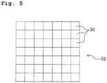
- the mirror elements 50 can be driven independently by the driving elements 5b respectively.
- the present invention is not limited to this; and it is possible to adopt various forms or modes in relation to the arrangement or construction of the wavefront change applying section which applies the wavefront change to the light allowed to pass through the optical system to be inspected.
- a fluid having a predetermined refractive index may be charged beforehand into a plurality of chambers or rooms which are comparted two-dimensionally; and the optical path length of each of the chambers and/or the refractive index of the fluid may be changed independently, thereby making it possible to apply the wavefront change to the light transmitted through the chambers.
- the light, which is transmitted through the wavefront change applying section can be reflected by using a plane mirror so that the light is returned to the optical system to be inspected.
Landscapes
- Physics & Mathematics (AREA)
- Geometry (AREA)
- Chemical & Material Sciences (AREA)
- Analytical Chemistry (AREA)
- General Physics & Mathematics (AREA)
- Testing Of Optical Devices Or Fibers (AREA)
Claims (13)
- Wellenfront-Aberration-Mess-Vorrichtung, die dazu eingerichtet ist, eine Wellenfront-Aberration eines optischen Systems (20, 21, 22), das untersucht werden soll, zu messen, die Wellenfront-Aberration-Mess-Vorrichtung aufweisend:eine Punktlichtquelle (1), welche dazu eingerichtet ist, ein Messlicht bereitzustellen;einen Fotodetektor (7), der eine Detektionsoberfläche hat, die an einer Position angeordnet ist, die optisch zu der Punktlichtquelle (1) konjugiert, wobei der Fotodetektor (7) dazu eingerichtet ist, eine Lichtintensität eines Lichtspots zu messen, der auf der Detektionsoberfläche gebildet ist; undeinen Wellenfrontänderung-Anwendungs-Abschnitt, welcher in einem optischen Pfad zwischen der Punktlichtquelle (1) und dem Fotodetektor (7) angeordnet ist und der eine Wellenfront-Änderung des Lichts bewirkt, das aus dem optischen System (20, 21, 22) austritt;dadurch gekennzeichnet, dass sie ferner aufweist:eine Steuerung (6), die dazu eingerichtet ist, den Wellenfrontänderung-Anwendungs-Abschnitt so zu steuern, dass die Lichtintensität des Lichtspots, welche mittels des Fotodetektors gemessen wird, maximiert ist; undeinen Messabschnitt, der dazu eingerichtet ist, die Wellenfront-Aberration des optischen Systems (20, ein 20, 22) basierend auf dem Ausgangssignal des Fotodetektors (7) und der Wellenfrontänderung, die mittels des Wellenfrontänderung-Anwendungs-Abschnitts bewirkt wird, in einem Zustand zu messen, in dem die Lichtintensität des Lichtspots, die von dem Fotodetektor gemessen wird, maximal ist.
- Wellenfront-Aberration-Mess-Vorrichtung nach Anspruch 1, wobei der Messabschnitt dazu eingerichtet ist, eine Exzentrizitätskomponente des optischen Systems (20, 21, 22) basierend auf einer Neigungskomponente der Wellenfrontänderung zu messen, die so angewendet wird, dass eine Position des Lichtspots, der auf der Detektionsoberfläche gebildet ist, zu einer vorgegebenen Position bewegt wird.
- Wellenfront-Aberration-Mess-Vorrichtung nach Anspruch 1, wobei der Messabschnitt dazu eingerichtet ist, eine Exzentrizitätskomponente des optischen Systems (20, 21, 22) basierend auf einer Positionsinformation über den Lichtspot, der auf der Detektionsoberfläche gebildet ist, zu messen.
- Wellenfront-Aberration-Mess-Vorrichtung nach einem der Ansprüche 1 bis 3, wobei der Wellenfrontänderung-Anwendungs-Abschnitt eine verformbare reflektierende Oberfläche und ein Treiberelement hat, welches die verformbare reflektierende Oberfläche bewegt.
- Wellenfront-Aberration-Mess-Vorrichtung nach einem der Ansprüche 1 bis 3, wobei der Wellenfrontänderung-Anwendungs-Abschnitt eine Mehrzahl von Spiegelelementen hat, die zweidimensional parallel angeordnet sind und deren Lage unabhängig verändert wird, und ein Treiberelement, das die Mehrzahl von Spiegelelementen bewegt.
- Wellenfront-Aberration-Mess-Vorrichtung nach einem der Ansprüche 1 bis 5, wobei die Lichtquelle (1) eine kohärente Lichtquelle (1) ist.
- Wellenfront-Aberration-Mess-Vorrichtung nach einem der Ansprüche 4 bis 5, wobei die Steuerung das Treiberelement so ansteuert, dass die Lichtintensität des Lichtspots, der auf der Detektionsoberfläche gebildet ist, maximal ist.
- Wellenfront-Aberration-Mess-Verfahren zum Messen einer Wellenfront-Aberration eines optischen Systems (20, 21, 22), das untersucht werden soll, das Wellenfront-Aberration-Mess-Verfahren aufweisend:Durchführen einer Wellenfrontänderung bei Licht, das von einer Punktlichtquelle (1) abgestrahlt wird und aus dem optischen System (20, 21, 22) austritt;Detektieren eines Lichtspots, der mittels des Lichts, bei dem die Wellenfrontänderung durchgeführt wird, auf einer vorgegebenen Oberfläche gebildet ist, die optisch zu der Punktlichtquelle (1) konjugiert; undMessen der Wellenfront-Aberration des optischen Systems (20, 21, 22) basierend auf der Wellenfrontänderung, die so durchgeführt wird, dass eine Lichtintensität des Lichtspots maximal ist.
- Wellenfront-Aberration-Mess-Verfahren nach Anspruch 8, wobei eine Exzentrizitätskomponente des optischen Systems (20, 21, 22) basierend auf der Wellenfrontänderung, die so durchgeführt wird, dass eine Position des Lichtspots an eine vorgegebene Position bewegt wird, gemessen wird.
- Wellenfront-Aberration-Mess-Verfahren nach Anspruch 8, wobei eine Exzentrizitätskomponente des optischen Systems (20, 21, 22) basierend auf einer Positionsinformation über den Lichtspot gemessen wird.
- Wellenfront-Aberration-Mess-Verfahren nach Anspruch 8, wobei die Wellenfrontänderung bei dem Licht durchgeführt wird, das aus dem optischen System (20, 21, 22) austritt, unter Verwendung eines verstellbaren Spiegels.
- Wellenfront-Aberration-Anpass-Verfahren zum Anpassen der Wellenfront-Aberration des optischen Systems (20, 21, 22) unter Verwendung der Wellenfront-Aberration, die in Übereinstimmung mit dem Wellenfront-Aberration-Mess-Verfahren, wie es in Anspruch 11 definiert ist, erhalten wird.
- Wellenfront-Aberration-Anpass-Verfahren zum Anpassen der Wellenfront-Aberration des optischen Systems (20, 21, 22) nach Anspruch 12, wobei der variable Spiegel in einem derartigen Zustand befestigt wird, dass eine gewünschte Wellenfront-Aberration erzeugt wird, mit Bezug zu dem optischen System (20, 21, 22), das die Wellenfront-Aberration eines bestimmten Werts hat, und dann die Wellenfront-Aberration des optischen Systems (20, 21, 22) so angepasst wird, dass die Lichtintensität des Lichtspots maximal ist.
Applications Claiming Priority (2)
| Application Number | Priority Date | Filing Date | Title |
|---|---|---|---|
| JP2007219215 | 2007-08-27 | ||
| PCT/JP2008/064523 WO2009028332A1 (ja) | 2007-08-27 | 2008-08-13 | 波面収差計測装置および方法、並びに波面収差調整方法 |
Publications (3)
| Publication Number | Publication Date |
|---|---|
| EP2184596A1 EP2184596A1 (de) | 2010-05-12 |
| EP2184596A4 EP2184596A4 (de) | 2012-12-05 |
| EP2184596B1 true EP2184596B1 (de) | 2018-11-14 |
Family
ID=40387058
Family Applications (1)
| Application Number | Title | Priority Date | Filing Date |
|---|---|---|---|
| EP08828535.8A Not-in-force EP2184596B1 (de) | 2007-08-27 | 2008-08-13 | Vorrichtung und verfahren zur messung von wellenfrontabweichungen sowie verfahren zur einstellung von wellenfrontabweichungen |
Country Status (6)
| Country | Link |
|---|---|
| US (1) | US8797520B2 (de) |
| EP (1) | EP2184596B1 (de) |
| JP (1) | JP5353112B2 (de) |
| CN (1) | CN101772696A (de) |
| TW (1) | TWI453381B (de) |
| WO (1) | WO2009028332A1 (de) |
Families Citing this family (15)
| Publication number | Priority date | Publication date | Assignee | Title |
|---|---|---|---|---|
| CN102109413B (zh) * | 2009-12-23 | 2012-06-13 | 富士迈半导体精密工业(上海)有限公司 | 均匀度测量系统与方法 |
| US8665425B2 (en) * | 2010-04-13 | 2014-03-04 | Konica Minolta Advanced Layers, Inc. | Eccentricity measuring method |
| CN102564731A (zh) * | 2010-12-16 | 2012-07-11 | 中国科学院西安光学精密机械研究所 | 一种透镜焦距及波前畸变测量装置 |
| CN102607719B (zh) * | 2011-06-24 | 2013-07-17 | 北京理工大学 | 基于横向剪切干涉的扩束准直系统波面像差检测装置 |
| CN102297759B (zh) * | 2011-06-24 | 2013-03-27 | 北京理工大学 | 基于横向剪切干涉的扩束准直系统波面像差检测方法 |
| CN104094095B (zh) * | 2012-02-10 | 2018-01-26 | 庄臣及庄臣视力保护公司 | 用于对眼科装置的波前进行测量的方法和设备 |
| JP2015087198A (ja) * | 2013-10-30 | 2015-05-07 | キヤノン株式会社 | 計測装置及び計測方法 |
| WO2016157344A1 (ja) * | 2015-03-27 | 2016-10-06 | オリンパス株式会社 | 波面計測装置及び波面計測方法 |
| JP6391550B2 (ja) * | 2015-11-13 | 2018-09-19 | 三菱電機株式会社 | 波面センサ及び波面処理方法 |
| RU2623702C1 (ru) * | 2016-07-19 | 2017-06-28 | федеральное государственное бюджетное образовательное учреждение высшего образования "Московский государственный технический университет имени Н.Э. Баумана (национальный исследовательский университет)" (МГТУ им. Н.Э. Баумана) | Устройство и способ определения радиуса кривизны крупногабаритных оптических деталей на основе датчика волнового фронта |
| RU2695085C2 (ru) * | 2017-10-24 | 2019-07-19 | Некоммерческое партнерство "Научный центр "Лазерные информационные технологии" НП НЦ "ЛИТ" | Способ определения радиуса кривизны вогнутой оптической сферической поверхности с центральным осевым отверстием методом оптической дальнометрии |
| CN108827595B (zh) * | 2018-03-12 | 2020-07-14 | 西安应用光学研究所 | 基于自适应理论光学系统加工误差的检测装置 |
| KR102781336B1 (ko) * | 2022-12-08 | 2025-03-18 | 한국표준과학연구원 | 피조간섭계와 샥-하트만 센서를 결합한 복합 파면검사 시스템 |
| KR20240127754A (ko) | 2023-02-16 | 2024-08-23 | 삼성전자주식회사 | 광학 계측 설비 |
| US12498293B2 (en) * | 2023-03-20 | 2025-12-16 | Mloptic Corp. | Multi-configurable wavefront tester |
Citations (1)
| Publication number | Priority date | Publication date | Assignee | Title |
|---|---|---|---|---|
| WO1998027863A1 (en) * | 1996-12-23 | 1998-07-02 | University Of Rochester | Apparatus for improving vision and resolution of retinal images |
Family Cites Families (18)
| Publication number | Priority date | Publication date | Assignee | Title |
|---|---|---|---|---|
| US4033696A (en) * | 1975-02-03 | 1977-07-05 | Nippon Kogaku K.K. | Lens meter |
| US4682025A (en) | 1984-04-13 | 1987-07-21 | Trw Inc. | Active mirror wavefront sensor |
| EP0158505B1 (de) | 1984-04-13 | 1989-07-12 | Trw Inc. | Aktiver Spiegel-Wellenfrontsensor |
| JPS61118639A (ja) * | 1984-11-15 | 1986-06-05 | Olympus Optical Co Ltd | 偏心量測定装置 |
| JPH0812127B2 (ja) * | 1988-11-11 | 1996-02-07 | オリンパス光学工業株式会社 | 曲率半径測定装置及び方法 |
| CA2169141A1 (en) * | 1995-04-07 | 1996-10-08 | Ivan Prikryl | Interferometer having a micromirror |
| JP3630983B2 (ja) * | 1998-04-23 | 2005-03-23 | キヤノン株式会社 | 波面収差測定方法及び波面収差測定装置 |
| US20060238710A1 (en) * | 1999-12-03 | 2006-10-26 | Manfred Dick | Method for determining vision defects and for collecting data for correcting vision defects of the eye by interaction of a patient with an examiner and apparatus therefor |
| JP3417399B2 (ja) * | 2001-01-17 | 2003-06-16 | 三菱電機株式会社 | 波面センサ |
| JP4157839B2 (ja) * | 2001-08-30 | 2008-10-01 | ユニバーシティー オブ ロチェスター | 生体眼の網膜領域撮像方法及びそのシステム |
| JP4266673B2 (ja) * | 2003-03-05 | 2009-05-20 | キヤノン株式会社 | 収差測定装置 |
| DE10360570B4 (de) * | 2003-12-22 | 2006-01-12 | Carl Zeiss | Optisches Meßsystem und optisches Meßverfahren |
| JP2005311296A (ja) * | 2004-03-25 | 2005-11-04 | Nikon Corp | 波面収差測定方法、波面収差測定系の校正方法、波面収差測定装置、及び投影露光装置 |
| JP4600047B2 (ja) * | 2005-01-13 | 2010-12-15 | 株式会社ニコン | 波面収差測定方法、波面収差測定装置、投影露光装置、投影光学系の製造方法 |
| JP2007078434A (ja) * | 2005-09-13 | 2007-03-29 | Canon Inc | 三次元位置測定装置、波面収差測定装置および三次元形状測定装置 |
| US7445335B2 (en) * | 2006-01-20 | 2008-11-04 | Clarity Medical Systems, Inc. | Sequential wavefront sensor |
| US7402785B2 (en) * | 2006-01-30 | 2008-07-22 | Science Applications International Corporation | System and method for correction of turbulence effects on laser or other transmission |
| US7443514B2 (en) * | 2006-10-02 | 2008-10-28 | Asml Holding N.V. | Diffractive null corrector employing a spatial light modulator |
-
2008
- 2008-08-13 EP EP08828535.8A patent/EP2184596B1/de not_active Not-in-force
- 2008-08-13 CN CN200880101961A patent/CN101772696A/zh active Pending
- 2008-08-13 WO PCT/JP2008/064523 patent/WO2009028332A1/ja not_active Ceased
- 2008-08-21 JP JP2008212434A patent/JP5353112B2/ja not_active Expired - Fee Related
- 2008-08-26 TW TW097132502A patent/TWI453381B/zh not_active IP Right Cessation
-
2010
- 2010-02-26 US US12/713,598 patent/US8797520B2/en not_active Expired - Fee Related
Patent Citations (1)
| Publication number | Priority date | Publication date | Assignee | Title |
|---|---|---|---|---|
| WO1998027863A1 (en) * | 1996-12-23 | 1998-07-02 | University Of Rochester | Apparatus for improving vision and resolution of retinal images |
Also Published As
| Publication number | Publication date |
|---|---|
| TWI453381B (zh) | 2014-09-21 |
| US8797520B2 (en) | 2014-08-05 |
| CN101772696A (zh) | 2010-07-07 |
| EP2184596A4 (de) | 2012-12-05 |
| WO2009028332A1 (ja) | 2009-03-05 |
| JP5353112B2 (ja) | 2013-11-27 |
| JP2009075090A (ja) | 2009-04-09 |
| TW200921062A (en) | 2009-05-16 |
| EP2184596A1 (de) | 2010-05-12 |
| US20100149549A1 (en) | 2010-06-17 |
Similar Documents
| Publication | Publication Date | Title |
|---|---|---|
| US8797520B2 (en) | Wavefront aberration measuring device and method and wavefront aberration adjusting method | |
| JP5079558B2 (ja) | 表面高さ検出方法および装置 | |
| AU2002313824B2 (en) | Ophthalmic wavefront measuring devices | |
| EP1326525B1 (de) | Vorrichtung zur messung von wellenfrontfehlern | |
| US7537341B2 (en) | Wavefront aberration compensating apparatus and ophthalmologic unit having the same | |
| AU2002313824A1 (en) | Ophthalmic wavefront measuring devices | |
| US20120218464A1 (en) | Method and system for structured light 3D camera | |
| AU2001294623A1 (en) | Method and apparatus for measuring wavefront aberrations | |
| EP3392698B1 (de) | Lichtumlenkungsvorrichtung, head-up-anzeigevorrichtung, optische schreibeinheit, bilderzeugende vorrichtung und objekterkennungsvorrichtung | |
| US7780291B2 (en) | Wavefront aberration compensating apparatus and opthalmologic unit having the same | |
| US20170324895A1 (en) | Autofocus system for a high speed periodically modulated variable focal length lens | |
| EP3238608B1 (de) | Augenhintergrundbildformungsvorrichtung | |
| EP4483137B1 (de) | Teleskop mit optischem ausrichtungssystem | |
| JP2011047901A (ja) | 波面収差計測装置 | |
| CN116678320B (zh) | 一种望远镜面型光学检测系统及方法 | |
| HK1077184A (en) | Ophthalmic waverfront measuring devices | |
| HK1065933B (en) | Ophthalmic wavefront measuring devices |
Legal Events
| Date | Code | Title | Description |
|---|---|---|---|
| PUAI | Public reference made under article 153(3) epc to a published international application that has entered the european phase |
Free format text: ORIGINAL CODE: 0009012 |
|
| 17P | Request for examination filed |
Effective date: 20100223 |
|
| AK | Designated contracting states |
Kind code of ref document: A1 Designated state(s): AT BE BG CH CY CZ DE DK EE ES FI FR GB GR HR HU IE IS IT LI LT LU LV MC MT NL NO PL PT RO SE SI SK TR |
|
| AX | Request for extension of the european patent |
Extension state: AL BA MK RS |
|
| RAP1 | Party data changed (applicant data changed or rights of an application transferred) |
Owner name: NIKON CORPORATION |
|
| DAX | Request for extension of the european patent (deleted) | ||
| A4 | Supplementary search report drawn up and despatched |
Effective date: 20121107 |
|
| RIC1 | Information provided on ipc code assigned before grant |
Ipc: G01M 11/02 20060101AFI20121031BHEP |
|
| RAP1 | Party data changed (applicant data changed or rights of an application transferred) |
Owner name: NIKON CORPORATION |
|
| 17Q | First examination report despatched |
Effective date: 20160216 |
|
| GRAP | Despatch of communication of intention to grant a patent |
Free format text: ORIGINAL CODE: EPIDOSNIGR1 |
|
| STAA | Information on the status of an ep patent application or granted ep patent |
Free format text: STATUS: GRANT OF PATENT IS INTENDED |
|
| INTG | Intention to grant announced |
Effective date: 20180601 |
|
| GRAS | Grant fee paid |
Free format text: ORIGINAL CODE: EPIDOSNIGR3 |
|
| GRAA | (expected) grant |
Free format text: ORIGINAL CODE: 0009210 |
|
| STAA | Information on the status of an ep patent application or granted ep patent |
Free format text: STATUS: THE PATENT HAS BEEN GRANTED |
|
| AK | Designated contracting states |
Kind code of ref document: B1 Designated state(s): AT BE BG CH CY CZ DE DK EE ES FI FR GB GR HR HU IE IS IT LI LT LU LV MC MT NL NO PL PT RO SE SI SK TR |
|
| REG | Reference to a national code |
Ref country code: GB Ref legal event code: FG4D |
|
| REG | Reference to a national code |
Ref country code: CH Ref legal event code: EP Ref country code: AT Ref legal event code: REF Ref document number: 1065406 Country of ref document: AT Kind code of ref document: T Effective date: 20181115 |
|
| REG | Reference to a national code |
Ref country code: DE Ref legal event code: R096 Ref document number: 602008057944 Country of ref document: DE |
|
| REG | Reference to a national code |
Ref country code: IE Ref legal event code: FG4D |
|
| REG | Reference to a national code |
Ref country code: NL Ref legal event code: MP Effective date: 20181114 |
|
| REG | Reference to a national code |
Ref country code: LT Ref legal event code: MG4D |
|
| REG | Reference to a national code |
Ref country code: AT Ref legal event code: MK05 Ref document number: 1065406 Country of ref document: AT Kind code of ref document: T Effective date: 20181114 |
|
| PG25 | Lapsed in a contracting state [announced via postgrant information from national office to epo] |
Ref country code: FI Free format text: LAPSE BECAUSE OF FAILURE TO SUBMIT A TRANSLATION OF THE DESCRIPTION OR TO PAY THE FEE WITHIN THE PRESCRIBED TIME-LIMIT Effective date: 20181114 Ref country code: LV Free format text: LAPSE BECAUSE OF FAILURE TO SUBMIT A TRANSLATION OF THE DESCRIPTION OR TO PAY THE FEE WITHIN THE PRESCRIBED TIME-LIMIT Effective date: 20181114 Ref country code: NO Free format text: LAPSE BECAUSE OF FAILURE TO SUBMIT A TRANSLATION OF THE DESCRIPTION OR TO PAY THE FEE WITHIN THE PRESCRIBED TIME-LIMIT Effective date: 20190214 Ref country code: HR Free format text: LAPSE BECAUSE OF FAILURE TO SUBMIT A TRANSLATION OF THE DESCRIPTION OR TO PAY THE FEE WITHIN THE PRESCRIBED TIME-LIMIT Effective date: 20181114 Ref country code: AT Free format text: LAPSE BECAUSE OF FAILURE TO SUBMIT A TRANSLATION OF THE DESCRIPTION OR TO PAY THE FEE WITHIN THE PRESCRIBED TIME-LIMIT Effective date: 20181114 Ref country code: ES Free format text: LAPSE BECAUSE OF FAILURE TO SUBMIT A TRANSLATION OF THE DESCRIPTION OR TO PAY THE FEE WITHIN THE PRESCRIBED TIME-LIMIT Effective date: 20181114 Ref country code: IS Free format text: LAPSE BECAUSE OF FAILURE TO SUBMIT A TRANSLATION OF THE DESCRIPTION OR TO PAY THE FEE WITHIN THE PRESCRIBED TIME-LIMIT Effective date: 20190314 Ref country code: BG Free format text: LAPSE BECAUSE OF FAILURE TO SUBMIT A TRANSLATION OF THE DESCRIPTION OR TO PAY THE FEE WITHIN THE PRESCRIBED TIME-LIMIT Effective date: 20190214 Ref country code: LT Free format text: LAPSE BECAUSE OF FAILURE TO SUBMIT A TRANSLATION OF THE DESCRIPTION OR TO PAY THE FEE WITHIN THE PRESCRIBED TIME-LIMIT Effective date: 20181114 |
|
| PG25 | Lapsed in a contracting state [announced via postgrant information from national office to epo] |
Ref country code: PT Free format text: LAPSE BECAUSE OF FAILURE TO SUBMIT A TRANSLATION OF THE DESCRIPTION OR TO PAY THE FEE WITHIN THE PRESCRIBED TIME-LIMIT Effective date: 20190314 Ref country code: NL Free format text: LAPSE BECAUSE OF FAILURE TO SUBMIT A TRANSLATION OF THE DESCRIPTION OR TO PAY THE FEE WITHIN THE PRESCRIBED TIME-LIMIT Effective date: 20181114 Ref country code: GR Free format text: LAPSE BECAUSE OF FAILURE TO SUBMIT A TRANSLATION OF THE DESCRIPTION OR TO PAY THE FEE WITHIN THE PRESCRIBED TIME-LIMIT Effective date: 20190215 Ref country code: SE Free format text: LAPSE BECAUSE OF FAILURE TO SUBMIT A TRANSLATION OF THE DESCRIPTION OR TO PAY THE FEE WITHIN THE PRESCRIBED TIME-LIMIT Effective date: 20181114 |
|
| PG25 | Lapsed in a contracting state [announced via postgrant information from national office to epo] |
Ref country code: IT Free format text: LAPSE BECAUSE OF FAILURE TO SUBMIT A TRANSLATION OF THE DESCRIPTION OR TO PAY THE FEE WITHIN THE PRESCRIBED TIME-LIMIT Effective date: 20181114 Ref country code: CZ Free format text: LAPSE BECAUSE OF FAILURE TO SUBMIT A TRANSLATION OF THE DESCRIPTION OR TO PAY THE FEE WITHIN THE PRESCRIBED TIME-LIMIT Effective date: 20181114 Ref country code: PL Free format text: LAPSE BECAUSE OF FAILURE TO SUBMIT A TRANSLATION OF THE DESCRIPTION OR TO PAY THE FEE WITHIN THE PRESCRIBED TIME-LIMIT Effective date: 20181114 Ref country code: DK Free format text: LAPSE BECAUSE OF FAILURE TO SUBMIT A TRANSLATION OF THE DESCRIPTION OR TO PAY THE FEE WITHIN THE PRESCRIBED TIME-LIMIT Effective date: 20181114 |
|
| REG | Reference to a national code |
Ref country code: DE Ref legal event code: R097 Ref document number: 602008057944 Country of ref document: DE |
|
| PG25 | Lapsed in a contracting state [announced via postgrant information from national office to epo] |
Ref country code: EE Free format text: LAPSE BECAUSE OF FAILURE TO SUBMIT A TRANSLATION OF THE DESCRIPTION OR TO PAY THE FEE WITHIN THE PRESCRIBED TIME-LIMIT Effective date: 20181114 Ref country code: SK Free format text: LAPSE BECAUSE OF FAILURE TO SUBMIT A TRANSLATION OF THE DESCRIPTION OR TO PAY THE FEE WITHIN THE PRESCRIBED TIME-LIMIT Effective date: 20181114 Ref country code: RO Free format text: LAPSE BECAUSE OF FAILURE TO SUBMIT A TRANSLATION OF THE DESCRIPTION OR TO PAY THE FEE WITHIN THE PRESCRIBED TIME-LIMIT Effective date: 20181114 |
|
| PLBE | No opposition filed within time limit |
Free format text: ORIGINAL CODE: 0009261 |
|
| STAA | Information on the status of an ep patent application or granted ep patent |
Free format text: STATUS: NO OPPOSITION FILED WITHIN TIME LIMIT |
|
| 26N | No opposition filed |
Effective date: 20190815 |
|
| PG25 | Lapsed in a contracting state [announced via postgrant information from national office to epo] |
Ref country code: SI Free format text: LAPSE BECAUSE OF FAILURE TO SUBMIT A TRANSLATION OF THE DESCRIPTION OR TO PAY THE FEE WITHIN THE PRESCRIBED TIME-LIMIT Effective date: 20181114 |
|
| PGFP | Annual fee paid to national office [announced via postgrant information from national office to epo] |
Ref country code: FR Payment date: 20190711 Year of fee payment: 12 |
|
| REG | Reference to a national code |
Ref country code: DE Ref legal event code: R119 Ref document number: 602008057944 Country of ref document: DE |
|
| PG25 | Lapsed in a contracting state [announced via postgrant information from national office to epo] |
Ref country code: TR Free format text: LAPSE BECAUSE OF FAILURE TO SUBMIT A TRANSLATION OF THE DESCRIPTION OR TO PAY THE FEE WITHIN THE PRESCRIBED TIME-LIMIT Effective date: 20181114 |
|
| GBPC | Gb: european patent ceased through non-payment of renewal fee |
Effective date: 20190813 |
|
| PG25 | Lapsed in a contracting state [announced via postgrant information from national office to epo] |
Ref country code: LI Free format text: LAPSE BECAUSE OF NON-PAYMENT OF DUE FEES Effective date: 20190831 Ref country code: CH Free format text: LAPSE BECAUSE OF NON-PAYMENT OF DUE FEES Effective date: 20190831 Ref country code: MC Free format text: LAPSE BECAUSE OF FAILURE TO SUBMIT A TRANSLATION OF THE DESCRIPTION OR TO PAY THE FEE WITHIN THE PRESCRIBED TIME-LIMIT Effective date: 20181114 Ref country code: LU Free format text: LAPSE BECAUSE OF NON-PAYMENT OF DUE FEES Effective date: 20190813 |
|
| REG | Reference to a national code |
Ref country code: BE Ref legal event code: MM Effective date: 20190831 |
|
| PG25 | Lapsed in a contracting state [announced via postgrant information from national office to epo] |
Ref country code: IE Free format text: LAPSE BECAUSE OF NON-PAYMENT OF DUE FEES Effective date: 20190813 Ref country code: DE Free format text: LAPSE BECAUSE OF NON-PAYMENT OF DUE FEES Effective date: 20200303 |
|
| PG25 | Lapsed in a contracting state [announced via postgrant information from national office to epo] |
Ref country code: BE Free format text: LAPSE BECAUSE OF NON-PAYMENT OF DUE FEES Effective date: 20190831 Ref country code: GB Free format text: LAPSE BECAUSE OF NON-PAYMENT OF DUE FEES Effective date: 20190813 |
|
| PG25 | Lapsed in a contracting state [announced via postgrant information from national office to epo] |
Ref country code: CY Free format text: LAPSE BECAUSE OF FAILURE TO SUBMIT A TRANSLATION OF THE DESCRIPTION OR TO PAY THE FEE WITHIN THE PRESCRIBED TIME-LIMIT Effective date: 20181114 |
|
| PG25 | Lapsed in a contracting state [announced via postgrant information from national office to epo] |
Ref country code: MT Free format text: LAPSE BECAUSE OF FAILURE TO SUBMIT A TRANSLATION OF THE DESCRIPTION OR TO PAY THE FEE WITHIN THE PRESCRIBED TIME-LIMIT Effective date: 20181114 Ref country code: FR Free format text: LAPSE BECAUSE OF NON-PAYMENT OF DUE FEES Effective date: 20200831 Ref country code: HU Free format text: LAPSE BECAUSE OF FAILURE TO SUBMIT A TRANSLATION OF THE DESCRIPTION OR TO PAY THE FEE WITHIN THE PRESCRIBED TIME-LIMIT; INVALID AB INITIO Effective date: 20080813 |