EP2184604B1 - Vorrichtung und Verfahren zur Identifizierung der Defektposition in Körpern, insbesondere in Holzkörpern wie Holzblöcken und Planken - Google Patents
Vorrichtung und Verfahren zur Identifizierung der Defektposition in Körpern, insbesondere in Holzkörpern wie Holzblöcken und Planken Download PDFInfo
- Publication number
- EP2184604B1 EP2184604B1 EP09166651.1A EP09166651A EP2184604B1 EP 2184604 B1 EP2184604 B1 EP 2184604B1 EP 09166651 A EP09166651 A EP 09166651A EP 2184604 B1 EP2184604 B1 EP 2184604B1
- Authority
- EP
- European Patent Office
- Prior art keywords
- beams
- feed
- defect
- emitter
- identifying
- Prior art date
- Legal status (The legal status is an assumption and is not a legal conclusion. Google has not performed a legal analysis and makes no representation as to the accuracy of the status listed.)
- Active
Links
Images


Classifications
-
- G—PHYSICS
- G01—MEASURING; TESTING
- G01N—INVESTIGATING OR ANALYSING MATERIALS BY DETERMINING THEIR CHEMICAL OR PHYSICAL PROPERTIES
- G01N33/00—Investigating or analysing materials by specific methods not covered by groups G01N1/00 - G01N31/00
- G01N33/46—Wood
-
- G—PHYSICS
- G01—MEASURING; TESTING
- G01N—INVESTIGATING OR ANALYSING MATERIALS BY DETERMINING THEIR CHEMICAL OR PHYSICAL PROPERTIES
- G01N23/00—Investigating or analysing materials by the use of wave or particle radiation, e.g. X-rays or neutrons, not covered by groups G01N3/00 – G01N17/00, G01N21/00 or G01N22/00
- G01N23/02—Investigating or analysing materials by the use of wave or particle radiation, e.g. X-rays or neutrons, not covered by groups G01N3/00 – G01N17/00, G01N21/00 or G01N22/00 by transmitting the radiation through the material
- G01N23/06—Investigating or analysing materials by the use of wave or particle radiation, e.g. X-rays or neutrons, not covered by groups G01N3/00 – G01N17/00, G01N21/00 or G01N22/00 by transmitting the radiation through the material and measuring the absorption
- G01N23/083—Investigating or analysing materials by the use of wave or particle radiation, e.g. X-rays or neutrons, not covered by groups G01N3/00 – G01N17/00, G01N21/00 or G01N22/00 by transmitting the radiation through the material and measuring the absorption the radiation being X-rays
Definitions
- the present invention relates to an apparatus and a method for identifying the position of defects, such as knots, cracks or cavities, in wooden bodies such as logs or planks.
- a first type of apparatus comprises two electromagnetic radiation emitters placed at a right angle to each other (usually one horizontal and one vertical) and lying in a plane which is perpendicular to a longitudinal axis of the log or plank, and also comprises two sensors positioned in such a way that each sensor receives the radiation emitted by one of the two emitters after it has passed through the wood.
- a second type of detection apparatus comprises a single emitter and a plurality of sensors aligned along a direction perpendicular to the longitudinal axis of the wooden log or plank (said longitudinal axis usually coincides with a log or plank feed direction) for detecting the intensity of the radiation emitted by the emitter after it has passed through the wood.
- the emitter generates a beam of electromagnetic radiation with a diverging shape, that is to say, its size increasing from the emitter towards the sensors, thus allowing the radiation emitted to cover all of the sensors.
- the analysis of the intensity of the radiation detected by each sensor allows identification of which sensors encountered an abnormal intensity and, therefore, the position where the defect in the wood is located.
- a third type of detection apparatus comprises a portal through which the log or plank to be analysed is passed.
- On the portal which is positioned perpendicularly to the longitudinal axis of the log or plank, there are two emitters generating respective diverging beams. The emitters are set at an angle to each other, so that the same points of the log or plank are struck from two different angles and therefore the defect is "observed" form two different points.
- the sensors are aligned in a row positioned perpendicularly to the longitudinal axis of the log and are located below the portal.
- the apparatuses of the first type described above usually require the log or plank to be held stationary during the detection step, having a significant negative impact on the productivity of the plants in which such apparatuses are included.
- the apparatuses of the first type require the use of two emitters which, as is well known, are amongst the most expensive components of a detection plant and therefore have a negative impact on plant production costs.
- Detection apparatuses of the second type only have one emitter, but the information that it can provide is not sufficient to correctly identify the position in space of defects in the log or plank detected.
- Each sensor measures an intensity of radiation received and, if abnormal values are measured, it means that there is a defect in the wood between the emitter and that sensor.
- apparatuses of the second type cannot provide any about the distance separating the defect from the emitter or from the sensor, since whatever the distance between the defect and the emitter or the sensor along a line linking them, the intensity detected by the sensor would be the same.
- Apparatuses of the third type similarly to those of the first type, have the disadvantage of requiring the use of two emitters, consequently increasing plant costs.
- US 2004/057551 discloses a method and an apparatus for mapping the relevant material properties of a log, such as knot location and extent.
- the outer shape of the log under bark is also revealed using that method, and the boundary between the heartwood and sapwood is mapped.
- the apparatus includes three x-ray sources for generating X-ray beams which lie in planes parallel to each other and perpendicular to the travel direction of the products to be examined, and arrays of x-ray detectors, for measuring the attenuation of the wood in the log. Deviations in attenuation are related to changes in density, which are indicative of knots and other defects. Accurate estimates of shape, density and knot location can be used for sawing decisions in sawmills, to improve the yield of high quality lumber from a given log.
- the techniques may also be used in a system for sorting logs according to quality.
- US5394342 discloses a log scanning system which uses X-ray beams which lie in planes parallel to each other and perpendicular to the travel direction of the products to be examined, for applying circumferentially spaced, traverse scans along the length of the log to provide a longitudinal density scan for each of the scans made.
- Each scan is elaborated to provide a spine image depicting spines of detected knots in each scan. Knot shapes, knot boundaries, roots or inner ends of the knots are also determined.
- the scans are then used to define the same knot in each of the reconstructed scans and then to generate a three-dimensional image of the log which may then be used by a sawing program to determine how the log should be sawed.
- the technical purpose of the present invention is to provide an apparatus and a method for identifying the position of defects in bodies, in particular in wooden bodies such as logs or planks, which overcomes the above-mentioned disadvantages.
- the present invention has for an aim to provide an apparatus and a method for identifying the position of defects in bodies, in particular in wooden bodies such as logs or planks, which allows precise identification of the three-dimensional position of any defects whilst at the same time keeping plant costs down.
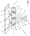
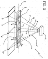
- the apparatus 1 comprises body 2 feed means 3 for moving the body 2 along a feed direction "A" which is preferably horizontal.
- the feed means 3 comprise a plurality of rollers 4 connected to motor means, not illustrated, for pulling the body 2 along the feed direction "A".
- the feed direction "A" coincides with a main direction of extension of the body 2.
- the apparatus 1 also comprises an emitter 5 for emitting a plurality of beams 6', 6", 6"' of electromagnetic radiation.
- the emitter 5 is an X-ray emitter.
- the beams 6', 6", 6"' lie in respective lying planes "P1", “P2"', "P3” extending from the emitter 5 and intersecting the body 2 which is opposite the emitter 5.
- the accompanying drawings show three beams 6', 6", 6"' for simplicity, however, other embodiments (not illustrated) are possible in which the emitter 5 is of the type designed to emit a larger number of beams, for example five, which in any event have the same properties as the three beams 6', 6", 6"'.
- the emitter 5 is of the type able to generate beams 6', 6", 6"' according to respective lying planes "P1", “P2"', “P3” which are set at different angles to the feed direction "A".
- each of the lying planes "P1", “P2”', “P3” is set at a different angle relative to the other lying planes "P1", “P2”', “P3” for intersecting the body 2 both at different points of the body 2 and according to different directions.
- the emitter 5 generates a plurality of beams 6', 6", 6"' diverging from each other away from the emitter 5 towards the body 2.
- Each beam 6', 6", 6"' is preferably sized so that it strikes an entire transversal dimension of the body 2, said transversal dimension being perpendicular to the feed direction "A", in particular horizontal.
- the central lying plane 6" is substantially perpendicular to the feed direction "A", more precisely it is vertical.
- the other lying planes "P1", “P3” are set at ah angle "G" to each.other, forming a maximum flare angle for the emitter 5 electromagnetic emission.
- the angle "G” is preferably 90 degrees.
- Figures 1 and 2 show, labelled 7', 7", 7"', the cross-sections of the body 2 identified by the intersection between the beams 6', 6", 6"' and the body 2. Said cross-sections 7', 7", 7"' are highlighted with dense background to highlight the different angles of the cross-sections 7', 7", 7"' caused by the different angles of the lying planes "P1", "P2"', "P3".
- the emitter 5 is positioned above the body 2 to be analysed.
- the apparatus 1 also comprises, on the opposite side of the body 2 relative to the emitter 5, that is to say, below the body 2, a plurality of sensors 8', 8'', 8"' whose number is preferably the same as the number of beams 6', 6", 6"'.
- Each sensor 8', 8", 8"' is designed to receive a respective beam 6', 6", 6"' of electromagnetic radiation after the beam 6', 6", 6"' has passed through the body 2.
- each sensor 8', 8", 8"' can measure a residual intensity of the respective beam 6', 6", 6"' to identify how much energy the beam 6', 6", 6"' lost as it passed through the body 2.
- the analysis of the energy absorbed by the body 2 in each of the cross-sections 7', 7", 7"' allows evaluation of the existence of a defect in one or more of the cross-sections 7', 7", 7"', since the presence of defects distorts the energy absorption values, making them greater than or less than an expected normal value, characteristic of wood which is free of defects.
- the apparatus 1 also comprises a processing unit, not illustrated, connected to the sensors 8', 8", 8"' and preferably also to the emitter 5 for receiving the intensity values of the beams 6', 6", 6"' emitted by the emitter 5 and detected by the sensors 8', 8", 8"'.
- the processing unit can also store said data and associate it with a relative moment in time in which it was detected, allowing subsequent processing of the data, even complex processing, as described below.
- FIGS 3 and 4 help to explain the operating principle of the apparatus 1 described above.
- the body 2 is then conveyed, by the feed means 3, through a space “S" between the emitter 5 and the sensors 8', 8", 8"' and is fed along the feed direction "A".
- the body 2 is fed with a known feed speed which is preferably kept constant at least during an entire body 2 detection step.
- Figure 3 shows a situation in which the defect 100 is located in a lower portion of the body 2, and shows the moment when the defect 100 encounters the central beam 6".
- the defect 100 is illustrated with a light line, whilst again is Figure 3 the same defect is labelled 200 at the moment when it reaches the last beam 6".
- Each sensor 8', 8", 8"' detects a continuous succession of residual intensity values of each beam 6', 6", 6"' which emerges from the body 2.
- each sensor 8', 8", 8"' detects a succession of residual intensity values of each beam 6', 6", 6"' at moments which are close together, so as to detect, with predetermined precision, when a defect 100 is close to the respective beam 6', 6", 6"' detected.
- the processing unit Since at the moment when a defect encounters a beam of electromagnetic radiation it modifies a beam energy absorption which is instantaneously detected by the sensor, which sends a corresponding signal to the processing unit, the processing unit is always able to recognise whether or not at a predetermined moment a defect 100 is passing through one of the beams. Therefore, at the moment when the defect 100 encounters the central beam 6", the respective central sensor 8" detects a residual intensity value in the beam 6" detected. The processing unit receives from the sensor 8" a signal identifying the abnormal energy absorption and, therefore, identifies the existence of a defect 100 passing through the central beam 6".
- the defect 100 reaches the last beam 6"', reaching the configuration shown in Figure 3 in which the defect is labelled 200 and shown with a thick line.
- the last sensor 8"' detects an abnormal residual intensity value in the last beam 6"' and this is associated with an abnormal energy absorption in that beam 6"' and, therefore, linked to a defect 200 passing through the last beam 6"'.
- the processing unit can identify' a distance "L1" travelled by the defect 100 between the central beam 6" and the last beam 6"'. Once said distance travelled "L1" information has been obtained, and knowing the geometry of the planes "P1", “P2"', "P3" in which the beams 6', 6", 6"' lie, the processing unit can unambiguously evaluate the vertical position of the defect 100, that is to say, the position of the defect 100 along a direction linking the emitter 5 with one of the sensors 8', 8", 8"'.
- the information detected regarding the residual intensity of each beam 6', 6", 6"' is processed and combined to identify the positioning in space of the defect 100 at a predetermined moment and, based on the knowledge of the body 2 feed speed and therefore the position of the body 2, to identify the position in space of the defect 100 inside the body 2.
- Figure 4 shows a defect 100 which is positioned higher up than the defect 100 of Figure 3 . Due to the configuration of the beams 6', 6", 6"' diverging from top to bottom, the defect 100 of Figure 4 must travel a distance "L2" which is less than the distance "L1” that must be travelled by the defect of 100 Figures 3 , in order to get from the central beam 6" to the last beam 6"'.
- each of the sensors 8', 8", 8"' comprises a plurality of sensitive elements (not illustrated) which are aligned along a direction perpendicular to the body 2 direction of feed "A", that is to say, perpendicular to the views of Figures 3 and 4 .
- the intensity of the radiation detected by each sensitive element this allows identification of the position of the defect 100 in a horizontal plane.
- Detection of the position of the defect 100 both in a vertical direction, or more generally in a direction linking the emitter 5 with one of the sensors 8', 8", 8"', and in a horizontal plane, that is to say, in a plane transversal to said linking direction, allows the three-dimensional positioning of the defect 100 inside the body 2 to be obtained.
- An alternative application of the apparatus 1 according to the present invention also allows precise estimation of an outer profile of the defect 100.
- Each point of the body 2 is struck one after another by each of the beams 6', 6", 6"' in three different directions, and for each of the three beams 6', 6", 6"' the energy absorption is measured by means of the respective sensor 8', 8", 8"'.
- Figure 5 shows an example of a detection of a defect 100 using five detections obtained with five beams of electromagnetic radiation, in which the thicker lines are segments whose length is linked, for example proportionally, to an absorption value detected by the sensors. Said detection is then repeated for a grid of body 2 points adjacent to each other so as to precisely identify the outer profile of the defect 100.
- the present invention achieves the preset aim, overcoming the disadvantages of the prior art.
- the apparatus according to the invention has only one electromagnetic radiation emitter, but comprises a plurality of sensors operating in conjunction with it. Since the sensors are much less expensive than an electromagnetic radiation emitter, and in particular an X-ray emitter, the apparatus is obviously significantly less expensive than other, prior art apparatuses.
- the method according to the invention allows, starting with the emission of beams of electromagnetic radiation from a single emitter, precise and reliable identification of the position in space of any defects present in the bodies detected. This also allows an estimate of the trend of the outer profile of the defect.
- the emitter were of the type able to generate more than three beams of electromagnetic radiation (consider even a very high number), it would be possible to very precisely identify both the position of defects which are superposed and/or located in positions close to each other, which would normally tend to blend with one another, also identifying the trend of the outer profile of said defects.
Landscapes
- Health & Medical Sciences (AREA)
- Life Sciences & Earth Sciences (AREA)
- Chemical & Material Sciences (AREA)
- Analytical Chemistry (AREA)
- General Health & Medical Sciences (AREA)
- Pathology (AREA)
- Immunology (AREA)
- Physics & Mathematics (AREA)
- Engineering & Computer Science (AREA)
- Biochemistry (AREA)
- General Physics & Mathematics (AREA)
- Wood Science & Technology (AREA)
- Medicinal Chemistry (AREA)
- Food Science & Technology (AREA)
- Toxicology (AREA)
- Investigating Or Analyzing Materials By The Use Of Ultrasonic Waves (AREA)
- Analysing Materials By The Use Of Radiation (AREA)
- Chemical And Physical Treatments For Wood And The Like (AREA)
- Machines For Manufacturing Corrugated Board In Mechanical Paper-Making Processes (AREA)
Claims (15)
- Vorrichtung zur Identifizierung der Defektposition (100) in Körpern (2), insbesondere in Holzkörpern wie Balken und Brettern, enthaltend:- einen einzelnen Emitter (5), welcher so platziert werden kann, dass er einem Körper (2) zugewandt ist, um eine Anzahl von Strahlen (6', 6", 6"') einer elektromagnetischen Strahlung auf den Körper (2) zu richten, wobei jeder der Strahlen (6', 6", 6"') in einer entsprechenden Lageebene (P1, P2, P3) verläuft;- eine Anzahl von Messfühlern (8', 8", 8"'), von welchen jeder dem Emitter (5) zugewandt ist, um einen der Strahlen (6', 6", 6"') zu empfangen, nachdem der Strahl (6', 6", 6"') durch den Körper (2) gegangen ist; wobei die Messfühler (8', 8", 8"') und der Emitter (5) zwischen sich einen Raum (S) abgrenzen, in welchem der Körper (2) positioniert ist;- Vorschubmittel (3) zum Bewegen des Körpers (2) entlang einer Vorschubrichtung (A) durch den Raum (S);wobei die Vorrichtung dadurch gekennzeichnet ist, dass die Ebenen (P1, P2, P3), in welcher die Strahlen (6', 6", 6"') liegen, in unterschiedlichen Winkeln zueinander angeordnet und quer zu der Vorschubrichtung (A) ausgerichtet sind, und wobei die Lageebenen (P1, P2, P3) eine hinter der anderen entlang der Vorschubrichtung (A) positioniert sind, so dass derselbe Abschnitt des Körpers (2) durch die aufeinanderfolgenden Strahlen (6', 6", 6"') getroffen werden kann, während der Körper (2) vorgeschoben wird.
- Vorrichtung nach Patentanspruch 1, dadurch gekennzeichnet, dass der Emitter (5) die Strahlen (6', 6", 6"') in Übereinstimmung mit einer Konfiguration erzeugt, die von dem Emitter (5) zu den Messfühlern (8', 8", 8"') divergiert.
- Vorrichtung nach Patentanspruch 1 oder 2, dadurch gekennzeichnet, dass der Emitter (5) die Strahlen (6', 6", 6"') mit einem Öffnungswinkel (G) erzeugt, welcher geringer oder gleich 90° ist, wobei der genannte Öffnungswinkel (G) zwischen einem ersten Strahl (6') und einem letzten Strahl (6"') im Verhältnis zu der Vorschubrichtung (A) gemessen wird.
- Vorrichtung nach einem oder mehreren der vorstehenden Patentansprüche, dadurch gekennzeichnet, dass sie einen einzigen Emitter (5) enthält.
- Vorrichtung nach einem oder mehreren der vorstehenden Patentansprüche, dadurch gekennzeichnet, dass die Messfühler (8', 8", 8"') einer nach dem anderen entlang der Vorschubrichtung (A) positioniert sind.
- Vorrichtung nach einem oder mehreren der vorstehenden Patentansprüche, dadurch gekennzeichnet, dass jeder Messfühler (8', 8", 8"') eine Anzahl von empfindlichen Elementen enthält, welche entlang einer Richtung quer zu der Vorschubrichtung (A) ausgerichtet sind, um die Defektposition (100) entlang der Querrichtung zu identifizieren.
- Vorrichtung nach einem oder mehreren der vorstehenden Patentansprüche, dadurch gekennzeichnet, dass sie eine Verarbeitungseinheit enthält, angeschlossen an die Messfühler (8', 8", 8"'), um von den Messfühleren (8', 8", 8"') die Intensitätswerte eines jeden der erfassten Strahlen (6', 6", 6"') zu empfangen, wobei die Verarbeitungseinheit ebenfalls die Vorschubgeschwindigkeit eines Körpers (2) entlang der Vorschubrichtung (A) erfasst.
- Verfahren zur Identifizierung der Defektposition in Körpern, insbesondere in Holzkörpern wie Balken und Brettern, enthaltend die folgenden Phasen in der Reihenfolge, in welcher sie aufgelistet sind:- Zuführen eines Körpers (2) entlang einer Vorschubrichtung (A);- Auftreffen auf wenigstens einen Abschnitt des Körpers (2) von einer Anzahl von Strahlen (6', 6", 6"') einer elektromagnetischen Strahlung, wobei jeder Strahl (6', 6", 6"') in einer entsprechenden Lageebene (P1, P2, P3) liegt;- Erfassen einer Restintensität eines jeden der Strahlen (6', 6", 6"'), nachdem diese aus dem Körper (2) ausgetreten sind, um die durch den genannten Abschnitt des Körpers (2) aufgenommene Energie zu bewerten;- Identifizierung einer in dem Körper (2) vorhandenen Defektposition (100);wobei das Verfahren dadurch gekennzeichnet ist, dass die Phase des Auftreffens auf wenigstens einen Teil des Körpers (2) eine Phase des Erzeugens, mit einem einzigen Emitter, einer Anzahl von Strahlen (6', 6", 6"') enthält, die in jeweiligen Lageebenen (P1, P2, P3) liegen, welche in unterschiedlichen Winkeln zu der Vorschubrichtung (A) auf solche Weise ausgerichtet sind, dass die Strahlen (6', 6", 6"') durch den Abschnitt des Körpers (2) gehen, und zwar an Punkten, angeordnet einer nach dem anderen entlang der Vorschubrichtung (A), wobei die Phase der Identifizierung der Defektposition (100) eine Phase der Verarbeitung von Informationen über die Strahlen (6', 6", 6"') enthält, die aus dem Körper (2) austreten.
- Verfahren nach Patentanspruch 8, dadurch gekennzeichnet, dass die Phase des Auftreffens auf wenigstens einen Abschnitt des Körpers (2) einer Anzahl von Strahlen (6', 6", 6") einer elektromagnetischen Strahlung gleichzeitig mit der Vorschubphase des Körpers (2) entlang der Vorschubrichtung (A) ausgeführt wird.
- Verfahren nach Patentanspruch 8 oder 9, dadurch gekennzeichnet, dass es nach den genannten Phasen eine weitere Phase enthält, und zwar:- Identifizierung in Zeitmomenten, wenn aufeinanderfolgende Messfühler (8', 8", 8"') den Durchlauf desselben Defektes durch den jeweiligen Strahl (6', 6", 6") erfassen, abgetastet durch einen jeden Messfühler (8', 8", 8"');- Berechnung, wenigstens implizit, der durch den Defekt (100) entlang der Vorschubrichtung (A) zurückgelegten Abstände (L1, L2) entsprechend der genannten Zeitmomente;- Identifizierung, basierend auf der genannten Berechnungsphase, einer Defektposition (100) wenigstens entlang einer Richtung, die den Emitter (5) mit einem der Messfühler (8', 8", 8") verbindet
- Verfahren nach Patentanspruch 10, dadurch gekennzeichnet, dass es eine andere Phase zur Identifizierung der Defektposition (100) in einer Ebene quer zu der Verbindungsrichtung des Emitters (5) mit dem Messfühler (8', 8", 8"') enthält, um in Zusammenwirkung mit der Defektposition (100) entlang der Verbindungsrichtung des Emitters (5) mit dem Messfühler (8', 8", 8"') eine räumliche Defektposition (100) im Verhältnis zu dem Körper (2) zu identifizieren.
- Verfahren nach Patentanspruch 10 oder 11, dadurch gekennzeichnet, dass die Phase der Identifizierung in Zeitmomenten, wenn aufeinanderfolgende Messfühler (8', 8", 8"') den Durchlauf desselben Defektes erfassen, eine Phase des Vergleichs eines Intensitätswertes für den an einen jeden Messfühler (8', 8", 8"') gelangenden Strahl (6', 6", 6"') mit einem erwarteten Wert enthält, wobei sich der erwartete Wert auf eine Intensität bezieht, welche bei Fehlen von Defekten (100) gemessen werden kann.
- Verfahren nach einem oder mehreren der Patentansprüche von 8 bis 12, dadurch gekennzeichnet, dass die Phase des Erfassens einer Restintensität eines jeden der Strahlen (6', 6", 6"'), nachdem diese aus dem Körper (2) ausgetreten sind, durch das Erfassen einer kontinuierlichen Folge von Intensitätswerten eines jeden Strahls (6', 6", 6") ausgeführt wird, wobei die Phase der Identifizierung einer Defektposition (100) eine Phase des Aussendens der Intensitätswerte eines jeden Strahls (6', 6", 6"') an eine Verarbeitungseinheit enthält.
- Verfahren nach einem oder mehreren der Patentansprüche von 8 bis 13, dadurch gekennzeichnet, dass die Phase des Auftreffens auf den genannten Abschnitt des Körpers (2) ausgeführt wird durch das Auftreffen auf die gesamte Querabmessung des genannten Abschnitts des Körpers (2), wobei die Querabmessung auf solche Weise ausgerichtet ist, dass sie lotrecht zu der Vorschubrichtung (A) verläuft.
- Verfahren nach einem oder mehreren der Patentansprüche von 8 bis 14, dadurch gekennzeichnet, dass die Phase des Vorlaufens des Körpers (2) entlang der Vorschubrichtung (A) durch das Zuführen des Körpers (2) mit einer konstanten Vorschubgeschwindigkeit erfolgt.
Applications Claiming Priority (1)
| Application Number | Priority Date | Filing Date | Title |
|---|---|---|---|
| ITVR2008A000104A IT1396830B1 (it) | 2008-09-18 | 2008-09-18 | Apparato e metodo per l'individuazione della posizione di difetti in corpi, in particolare corpi lignei quali tronchi o tavole |
Publications (4)
| Publication Number | Publication Date |
|---|---|
| EP2184604A2 EP2184604A2 (de) | 2010-05-12 |
| EP2184604A3 EP2184604A3 (de) | 2010-06-02 |
| EP2184604A9 EP2184604A9 (de) | 2010-09-29 |
| EP2184604B1 true EP2184604B1 (de) | 2016-09-07 |
Family
ID=40778201
Family Applications (1)
| Application Number | Title | Priority Date | Filing Date |
|---|---|---|---|
| EP09166651.1A Active EP2184604B1 (de) | 2008-09-18 | 2009-07-28 | Vorrichtung und Verfahren zur Identifizierung der Defektposition in Körpern, insbesondere in Holzkörpern wie Holzblöcken und Planken |
Country Status (4)
| Country | Link |
|---|---|
| US (1) | US8306761B2 (de) |
| EP (1) | EP2184604B1 (de) |
| CA (1) | CA2675549C (de) |
| IT (1) | IT1396830B1 (de) |
Families Citing this family (1)
| Publication number | Priority date | Publication date | Assignee | Title |
|---|---|---|---|---|
| US9147014B2 (en) | 2011-08-31 | 2015-09-29 | Woodtech Measurement Solutions | System and method for image selection of bundled objects |
Family Cites Families (5)
| Publication number | Priority date | Publication date | Assignee | Title |
|---|---|---|---|---|
| US5394342A (en) * | 1993-02-26 | 1995-02-28 | Macmillan Bloedel Limited | Log scanning |
| FI103436B1 (fi) * | 1996-02-27 | 1999-06-30 | Bintec Oy | Menetelmä liikkuvan kappaleen, kuten tukin ominaisuuksien selvittämiseksi |
| US6757354B2 (en) * | 2002-09-20 | 2004-06-29 | Invision Technologies, Inc. | Multi-view x-ray imaging of logs |
| AT412423B (de) * | 2002-11-14 | 2005-02-25 | Microtec Srl | Vorrichtung, oberflächenprüfvorrichtung und verfahren zur aufzeichnung der obeflächenbeschaffenheit |
| US7149633B2 (en) * | 2004-02-26 | 2006-12-12 | Coe Newnes/Mcgettee Inc. | Displacement method of knot sizing |
-
2008
- 2008-09-18 IT ITVR2008A000104A patent/IT1396830B1/it active
-
2009
- 2009-07-28 EP EP09166651.1A patent/EP2184604B1/de active Active
- 2009-08-14 CA CA2675549A patent/CA2675549C/en active Active
- 2009-09-02 US US12/552,388 patent/US8306761B2/en active Active
Non-Patent Citations (1)
| Title |
|---|
| None * |
Also Published As
| Publication number | Publication date |
|---|---|
| EP2184604A3 (de) | 2010-06-02 |
| CA2675549C (en) | 2017-05-09 |
| US20100228500A1 (en) | 2010-09-09 |
| CA2675549A1 (en) | 2010-03-18 |
| ITVR20080104A1 (it) | 2010-03-19 |
| EP2184604A9 (de) | 2010-09-29 |
| IT1396830B1 (it) | 2012-12-14 |
| EP2184604A2 (de) | 2010-05-12 |
| US8306761B2 (en) | 2012-11-06 |
Similar Documents
| Publication | Publication Date | Title |
|---|---|---|
| RU2653111C2 (ru) | Способ обмера лесоматериала и соответствующее устройство | |
| US6757354B2 (en) | Multi-view x-ray imaging of logs | |
| US6151379A (en) | Method and device for measuring density | |
| EP2041552B1 (de) | Verfahren zur messung des volumens oder des endflächendurchmessers eines baumstamms sowie zur qualitätskontrolle | |
| SE504547C2 (sv) | Virkesoptimeringssystem samt förfarande för kvistdefiniering | |
| JP5347896B2 (ja) | 非破壊検査方法及びその装置 | |
| EP3991547B1 (de) | Verarbeitungskopf für eine forstwirtschaftliche maschine | |
| US6756789B1 (en) | Method for imaging logs or stems and apparatus | |
| US20130235372A1 (en) | Measuring device and method for determining a measured variable at one end of a rod-shaped product | |
| EP0765471B1 (de) | Anordnung und verfahren zum nachweis von fehlern im holz | |
| US20020043108A1 (en) | Method and apparatus for detecting and characterizing splits in logs | |
| US20080197054A1 (en) | Means and Method for Classifying Logs | |
| EP2184604B1 (de) | Vorrichtung und Verfahren zur Identifizierung der Defektposition in Körpern, insbesondere in Holzkörpern wie Holzblöcken und Planken | |
| US9063061B2 (en) | Detection of an anomaly in a biological material | |
| AU2017200609B2 (en) | A method of estimating timber stiffness profiles | |
| EP2295963B1 (de) | Verfahren und Vorrichtung zur Bestimmung des Verhältnisses von Ästen zum Volumen in Holzbrettern | |
| US20110058156A1 (en) | Method and device for determining the mass and/or a mass proportion of a wall section of a plastic bottle | |
| RU2449265C1 (ru) | Способ и устройство определения плотности древесины | |
| Halabe et al. | Advanced lumber manufacturing model for increasing yield in sawmills using GPR-based defect detection system | |
| EP2829876B1 (de) | Verfahren und Vorrichtung zur Abschätzung der Projektion auf eine Referenzebene der Richtung der Fasern eines Teils eines Holzbrettes | |
| NZ515405A (en) | Wood piece imaging for defects by microwave reflection | |
| SE516174C2 (sv) | Anordning för detektion av kapsprickor vid skördaraggregat för skogsavverkning | |
| NZ610108B2 (en) | A method of estimating timber stiffness profiles | |
| NZ610108A (en) | A method of estimating timber stiffness profiles |
Legal Events
| Date | Code | Title | Description |
|---|---|---|---|
| PUAI | Public reference made under article 153(3) epc to a published international application that has entered the european phase |
Free format text: ORIGINAL CODE: 0009012 |
|
| PUAL | Search report despatched |
Free format text: ORIGINAL CODE: 0009013 |
|
| AK | Designated contracting states |
Kind code of ref document: A2 Designated state(s): AT BE BG CH CY CZ DE DK EE ES FI FR GB GR HR HU IE IS IT LI LT LU LV MC MK MT NL NO PL PT RO SE SI SK SM TR |
|
| AX | Request for extension of the european patent |
Extension state: AL BA RS |
|
| AK | Designated contracting states |
Kind code of ref document: A3 Designated state(s): AT BE BG CH CY CZ DE DK EE ES FI FR GB GR HR HU IE IS IT LI LT LU LV MC MK MT NL NO PL PT RO SE SI SK SM TR |
|
| AX | Request for extension of the european patent |
Extension state: AL BA RS |
|
| RIC1 | Information provided on ipc code assigned before grant |
Ipc: G01N 33/46 20060101ALI20100429BHEP Ipc: G01N 23/12 20060101AFI20100429BHEP |
|
| 17P | Request for examination filed |
Effective date: 20101004 |
|
| 17Q | First examination report despatched |
Effective date: 20150507 |
|
| GRAP | Despatch of communication of intention to grant a patent |
Free format text: ORIGINAL CODE: EPIDOSNIGR1 |
|
| INTG | Intention to grant announced |
Effective date: 20160322 |
|
| GRAP | Despatch of communication of intention to grant a patent |
Free format text: ORIGINAL CODE: EPIDOSNIGR1 |
|
| INTG | Intention to grant announced |
Effective date: 20160622 |
|
| GRAS | Grant fee paid |
Free format text: ORIGINAL CODE: EPIDOSNIGR3 |
|
| GRAA | (expected) grant |
Free format text: ORIGINAL CODE: 0009210 |
|
| AK | Designated contracting states |
Kind code of ref document: B1 Designated state(s): AT BE BG CH CY CZ DE DK EE ES FI FR GB GR HR HU IE IS IT LI LT LU LV MC MK MT NL NO PL PT RO SE SI SK SM TR |
|
| REG | Reference to a national code |
Ref country code: GB Ref legal event code: FG4D |
|
| REG | Reference to a national code |
Ref country code: CH Ref legal event code: EP |
|
| REG | Reference to a national code |
Ref country code: IE Ref legal event code: FG4D |
|
| REG | Reference to a national code |
Ref country code: AT Ref legal event code: REF Ref document number: 827311 Country of ref document: AT Kind code of ref document: T Effective date: 20161015 |
|
| REG | Reference to a national code |
Ref country code: DE Ref legal event code: R096 Ref document number: 602009040912 Country of ref document: DE |
|
| REG | Reference to a national code |
Ref country code: SE Ref legal event code: TRGR |
|
| REG | Reference to a national code |
Ref country code: LT Ref legal event code: MG4D |
|
| REG | Reference to a national code |
Ref country code: NL Ref legal event code: MP Effective date: 20160907 |
|
| PG25 | Lapsed in a contracting state [announced via postgrant information from national office to epo] |
Ref country code: FI Free format text: LAPSE BECAUSE OF FAILURE TO SUBMIT A TRANSLATION OF THE DESCRIPTION OR TO PAY THE FEE WITHIN THE PRESCRIBED TIME-LIMIT Effective date: 20160907 Ref country code: NO Free format text: LAPSE BECAUSE OF FAILURE TO SUBMIT A TRANSLATION OF THE DESCRIPTION OR TO PAY THE FEE WITHIN THE PRESCRIBED TIME-LIMIT Effective date: 20161207 Ref country code: HR Free format text: LAPSE BECAUSE OF FAILURE TO SUBMIT A TRANSLATION OF THE DESCRIPTION OR TO PAY THE FEE WITHIN THE PRESCRIBED TIME-LIMIT Effective date: 20160907 Ref country code: LT Free format text: LAPSE BECAUSE OF FAILURE TO SUBMIT A TRANSLATION OF THE DESCRIPTION OR TO PAY THE FEE WITHIN THE PRESCRIBED TIME-LIMIT Effective date: 20160907 |
|
| REG | Reference to a national code |
Ref country code: AT Ref legal event code: MK05 Ref document number: 827311 Country of ref document: AT Kind code of ref document: T Effective date: 20160907 |
|
| PG25 | Lapsed in a contracting state [announced via postgrant information from national office to epo] |
Ref country code: ES Free format text: LAPSE BECAUSE OF FAILURE TO SUBMIT A TRANSLATION OF THE DESCRIPTION OR TO PAY THE FEE WITHIN THE PRESCRIBED TIME-LIMIT Effective date: 20160907 Ref country code: GR Free format text: LAPSE BECAUSE OF FAILURE TO SUBMIT A TRANSLATION OF THE DESCRIPTION OR TO PAY THE FEE WITHIN THE PRESCRIBED TIME-LIMIT Effective date: 20161208 Ref country code: NL Free format text: LAPSE BECAUSE OF FAILURE TO SUBMIT A TRANSLATION OF THE DESCRIPTION OR TO PAY THE FEE WITHIN THE PRESCRIBED TIME-LIMIT Effective date: 20160907 Ref country code: LV Free format text: LAPSE BECAUSE OF FAILURE TO SUBMIT A TRANSLATION OF THE DESCRIPTION OR TO PAY THE FEE WITHIN THE PRESCRIBED TIME-LIMIT Effective date: 20160907 |
|
| PG25 | Lapsed in a contracting state [announced via postgrant information from national office to epo] |
Ref country code: RO Free format text: LAPSE BECAUSE OF FAILURE TO SUBMIT A TRANSLATION OF THE DESCRIPTION OR TO PAY THE FEE WITHIN THE PRESCRIBED TIME-LIMIT Effective date: 20160907 Ref country code: EE Free format text: LAPSE BECAUSE OF FAILURE TO SUBMIT A TRANSLATION OF THE DESCRIPTION OR TO PAY THE FEE WITHIN THE PRESCRIBED TIME-LIMIT Effective date: 20160907 |
|
| PG25 | Lapsed in a contracting state [announced via postgrant information from national office to epo] |
Ref country code: SM Free format text: LAPSE BECAUSE OF FAILURE TO SUBMIT A TRANSLATION OF THE DESCRIPTION OR TO PAY THE FEE WITHIN THE PRESCRIBED TIME-LIMIT Effective date: 20160907 Ref country code: CZ Free format text: LAPSE BECAUSE OF FAILURE TO SUBMIT A TRANSLATION OF THE DESCRIPTION OR TO PAY THE FEE WITHIN THE PRESCRIBED TIME-LIMIT Effective date: 20160907 Ref country code: IS Free format text: LAPSE BECAUSE OF FAILURE TO SUBMIT A TRANSLATION OF THE DESCRIPTION OR TO PAY THE FEE WITHIN THE PRESCRIBED TIME-LIMIT Effective date: 20170107 Ref country code: BG Free format text: LAPSE BECAUSE OF FAILURE TO SUBMIT A TRANSLATION OF THE DESCRIPTION OR TO PAY THE FEE WITHIN THE PRESCRIBED TIME-LIMIT Effective date: 20161207 Ref country code: AT Free format text: LAPSE BECAUSE OF FAILURE TO SUBMIT A TRANSLATION OF THE DESCRIPTION OR TO PAY THE FEE WITHIN THE PRESCRIBED TIME-LIMIT Effective date: 20160907 Ref country code: PT Free format text: LAPSE BECAUSE OF FAILURE TO SUBMIT A TRANSLATION OF THE DESCRIPTION OR TO PAY THE FEE WITHIN THE PRESCRIBED TIME-LIMIT Effective date: 20170109 Ref country code: PL Free format text: LAPSE BECAUSE OF FAILURE TO SUBMIT A TRANSLATION OF THE DESCRIPTION OR TO PAY THE FEE WITHIN THE PRESCRIBED TIME-LIMIT Effective date: 20160907 Ref country code: SK Free format text: LAPSE BECAUSE OF FAILURE TO SUBMIT A TRANSLATION OF THE DESCRIPTION OR TO PAY THE FEE WITHIN THE PRESCRIBED TIME-LIMIT Effective date: 20160907 Ref country code: BE Free format text: LAPSE BECAUSE OF FAILURE TO SUBMIT A TRANSLATION OF THE DESCRIPTION OR TO PAY THE FEE WITHIN THE PRESCRIBED TIME-LIMIT Effective date: 20160907 |
|
| REG | Reference to a national code |
Ref country code: DE Ref legal event code: R097 Ref document number: 602009040912 Country of ref document: DE |
|
| PLBE | No opposition filed within time limit |
Free format text: ORIGINAL CODE: 0009261 |
|
| STAA | Information on the status of an ep patent application or granted ep patent |
Free format text: STATUS: NO OPPOSITION FILED WITHIN TIME LIMIT |
|
| REG | Reference to a national code |
Ref country code: FR Ref legal event code: PLFP Year of fee payment: 9 |
|
| PG25 | Lapsed in a contracting state [announced via postgrant information from national office to epo] |
Ref country code: DK Free format text: LAPSE BECAUSE OF FAILURE TO SUBMIT A TRANSLATION OF THE DESCRIPTION OR TO PAY THE FEE WITHIN THE PRESCRIBED TIME-LIMIT Effective date: 20160907 |
|
| 26N | No opposition filed |
Effective date: 20170608 |
|
| PG25 | Lapsed in a contracting state [announced via postgrant information from national office to epo] |
Ref country code: SI Free format text: LAPSE BECAUSE OF FAILURE TO SUBMIT A TRANSLATION OF THE DESCRIPTION OR TO PAY THE FEE WITHIN THE PRESCRIBED TIME-LIMIT Effective date: 20160907 |
|
| REG | Reference to a national code |
Ref country code: CH Ref legal event code: PL |
|
| GBPC | Gb: european patent ceased through non-payment of renewal fee |
Effective date: 20170728 |
|
| REG | Reference to a national code |
Ref country code: IE Ref legal event code: MM4A |
|
| PG25 | Lapsed in a contracting state [announced via postgrant information from national office to epo] |
Ref country code: CH Free format text: LAPSE BECAUSE OF NON-PAYMENT OF DUE FEES Effective date: 20170731 Ref country code: GB Free format text: LAPSE BECAUSE OF NON-PAYMENT OF DUE FEES Effective date: 20170728 Ref country code: LI Free format text: LAPSE BECAUSE OF NON-PAYMENT OF DUE FEES Effective date: 20170731 Ref country code: IE Free format text: LAPSE BECAUSE OF NON-PAYMENT OF DUE FEES Effective date: 20170728 |
|
| REG | Reference to a national code |
Ref country code: FR Ref legal event code: PLFP Year of fee payment: 10 |
|
| PG25 | Lapsed in a contracting state [announced via postgrant information from national office to epo] |
Ref country code: MT Free format text: LAPSE BECAUSE OF NON-PAYMENT OF DUE FEES Effective date: 20170728 |
|
| PG25 | Lapsed in a contracting state [announced via postgrant information from national office to epo] |
Ref country code: HU Free format text: LAPSE BECAUSE OF FAILURE TO SUBMIT A TRANSLATION OF THE DESCRIPTION OR TO PAY THE FEE WITHIN THE PRESCRIBED TIME-LIMIT; INVALID AB INITIO Effective date: 20090728 Ref country code: MC Free format text: LAPSE BECAUSE OF FAILURE TO SUBMIT A TRANSLATION OF THE DESCRIPTION OR TO PAY THE FEE WITHIN THE PRESCRIBED TIME-LIMIT Effective date: 20160907 |
|
| PG25 | Lapsed in a contracting state [announced via postgrant information from national office to epo] |
Ref country code: CY Free format text: LAPSE BECAUSE OF NON-PAYMENT OF DUE FEES Effective date: 20160907 |
|
| PG25 | Lapsed in a contracting state [announced via postgrant information from national office to epo] |
Ref country code: MK Free format text: LAPSE BECAUSE OF FAILURE TO SUBMIT A TRANSLATION OF THE DESCRIPTION OR TO PAY THE FEE WITHIN THE PRESCRIBED TIME-LIMIT Effective date: 20160907 |
|
| PG25 | Lapsed in a contracting state [announced via postgrant information from national office to epo] |
Ref country code: TR Free format text: LAPSE BECAUSE OF FAILURE TO SUBMIT A TRANSLATION OF THE DESCRIPTION OR TO PAY THE FEE WITHIN THE PRESCRIBED TIME-LIMIT Effective date: 20160907 |
|
| P01 | Opt-out of the competence of the unified patent court (upc) registered |
Effective date: 20230524 |
|
| PGFP | Annual fee paid to national office [announced via postgrant information from national office to epo] |
Ref country code: LU Payment date: 20250724 Year of fee payment: 17 |
|
| PGFP | Annual fee paid to national office [announced via postgrant information from national office to epo] |
Ref country code: DE Payment date: 20250728 Year of fee payment: 17 |
|
| PGFP | Annual fee paid to national office [announced via postgrant information from national office to epo] |
Ref country code: IT Payment date: 20250721 Year of fee payment: 17 |
|
| PGFP | Annual fee paid to national office [announced via postgrant information from national office to epo] |
Ref country code: FR Payment date: 20250725 Year of fee payment: 17 |
|
| PGFP | Annual fee paid to national office [announced via postgrant information from national office to epo] |
Ref country code: SE Payment date: 20250725 Year of fee payment: 17 |
|
| REG | Reference to a national code |
Ref country code: DE Ref legal event code: R081 Ref document number: 602009040912 Country of ref document: DE Owner name: MICROTEC S.P.A., BRESSANONE, IT Free format text: FORMER OWNER: MICROTEC S.R.L., BRESSANONE, BOLZANO, IT |
|
| REG | Reference to a national code |
Ref country code: LU Ref legal event code: HC Owner name: MICROTEC S.P.A.; IT Free format text: FORMER OWNER: MICROTEC S.R.L. Effective date: 20251110 |