EP2184630B1 - Procédé de fabrication d'un cable pour le branchement d'abonné doté d'une cavité ovale - Google Patents
Procédé de fabrication d'un cable pour le branchement d'abonné doté d'une cavité ovale Download PDFInfo
- Publication number
- EP2184630B1 EP2184630B1 EP09175029.9A EP09175029A EP2184630B1 EP 2184630 B1 EP2184630 B1 EP 2184630B1 EP 09175029 A EP09175029 A EP 09175029A EP 2184630 B1 EP2184630 B1 EP 2184630B1
- Authority
- EP
- European Patent Office
- Prior art keywords
- fiber
- drop cable
- cavity
- cable
- oval
- Prior art date
- Legal status (The legal status is an assumption and is not a legal conclusion. Google has not performed a legal analysis and makes no representation as to the accuracy of the status listed.)
- Not-in-force
Links
- 238000000034 method Methods 0.000 title claims description 40
- 238000004519 manufacturing process Methods 0.000 title description 5
- 239000000835 fiber Substances 0.000 claims description 86
- 239000000463 material Substances 0.000 claims description 41
- 230000001681 protective effect Effects 0.000 claims description 41
- 239000013307 optical fiber Substances 0.000 claims description 28
- 238000001125 extrusion Methods 0.000 claims description 21
- 239000000843 powder Substances 0.000 description 8
- 238000001816 cooling Methods 0.000 description 7
- 238000004891 communication Methods 0.000 description 4
- 238000009826 distribution Methods 0.000 description 4
- 230000015572 biosynthetic process Effects 0.000 description 3
- 230000007423 decrease Effects 0.000 description 3
- 238000013459 approach Methods 0.000 description 2
- 230000000694 effects Effects 0.000 description 2
- 230000007613 environmental effect Effects 0.000 description 2
- 239000011152 fibreglass Substances 0.000 description 2
- 238000003860 storage Methods 0.000 description 2
- XLYOFNOQVPJJNP-UHFFFAOYSA-N water Substances O XLYOFNOQVPJJNP-UHFFFAOYSA-N 0.000 description 2
- NIXOWILDQLNWCW-UHFFFAOYSA-M Acrylate Chemical compound [O-]C(=O)C=C NIXOWILDQLNWCW-UHFFFAOYSA-M 0.000 description 1
- 206010034701 Peroneal nerve palsy Diseases 0.000 description 1
- 239000004952 Polyamide Substances 0.000 description 1
- 239000004698 Polyethylene Substances 0.000 description 1
- 229910000831 Steel Inorganic materials 0.000 description 1
- 239000002250 absorbent Substances 0.000 description 1
- WYTGDNHDOZPMIW-RCBQFDQVSA-N alstonine Natural products C1=CC2=C3C=CC=CC3=NC2=C2N1C[C@H]1[C@H](C)OC=C(C(=O)OC)[C@H]1C2 WYTGDNHDOZPMIW-RCBQFDQVSA-N 0.000 description 1
- 239000004760 aramid Substances 0.000 description 1
- 229920003235 aromatic polyamide Polymers 0.000 description 1
- 230000000712 assembly Effects 0.000 description 1
- 238000000429 assembly Methods 0.000 description 1
- 230000009286 beneficial effect Effects 0.000 description 1
- 230000005540 biological transmission Effects 0.000 description 1
- 230000000903 blocking effect Effects 0.000 description 1
- 230000003139 buffering effect Effects 0.000 description 1
- 238000009933 burial Methods 0.000 description 1
- 150000001875 compounds Chemical class 0.000 description 1
- 239000012809 cooling fluid Substances 0.000 description 1
- 230000001351 cycling effect Effects 0.000 description 1
- 238000005516 engineering process Methods 0.000 description 1
- 239000002360 explosive Substances 0.000 description 1
- 239000007788 liquid Substances 0.000 description 1
- 229920001179 medium density polyethylene Polymers 0.000 description 1
- 239000004701 medium-density polyethylene Substances 0.000 description 1
- 239000000155 melt Substances 0.000 description 1
- 230000003287 optical effect Effects 0.000 description 1
- 229920002647 polyamide Polymers 0.000 description 1
- -1 polyethylene Polymers 0.000 description 1
- 229920000573 polyethylene Polymers 0.000 description 1
- 229920000642 polymer Polymers 0.000 description 1
- 239000004800 polyvinyl chloride Substances 0.000 description 1
- 239000002994 raw material Substances 0.000 description 1
- 239000010959 steel Substances 0.000 description 1
- 229920001169 thermoplastic Polymers 0.000 description 1
- 239000004416 thermosoftening plastic Substances 0.000 description 1
- 230000009466 transformation Effects 0.000 description 1
Images


Classifications
-
- G—PHYSICS
- G02—OPTICS
- G02B—OPTICAL ELEMENTS, SYSTEMS OR APPARATUS
- G02B6/00—Light guides; Structural details of arrangements comprising light guides and other optical elements, e.g. couplings
- G02B6/44—Mechanical structures for providing tensile strength and external protection for fibres, e.g. optical transmission cables
- G02B6/4401—Optical cables
- G02B6/4429—Means specially adapted for strengthening or protecting the cables
- G02B6/443—Protective covering
- G02B6/4432—Protective covering with fibre reinforcements
- G02B6/4433—Double reinforcement laying in straight line with optical transmission element
-
- G—PHYSICS
- G02—OPTICS
- G02B—OPTICAL ELEMENTS, SYSTEMS OR APPARATUS
- G02B6/00—Light guides; Structural details of arrangements comprising light guides and other optical elements, e.g. couplings
- G02B6/44—Mechanical structures for providing tensile strength and external protection for fibres, e.g. optical transmission cables
- G02B6/4401—Optical cables
- G02B6/4402—Optical cables with one single optical waveguide
-
- G—PHYSICS
- G02—OPTICS
- G02B—OPTICAL ELEMENTS, SYSTEMS OR APPARATUS
- G02B6/00—Light guides; Structural details of arrangements comprising light guides and other optical elements, e.g. couplings
- G02B6/44—Mechanical structures for providing tensile strength and external protection for fibres, e.g. optical transmission cables
- G02B6/4401—Optical cables
- G02B6/441—Optical cables built up from sub-bundles
- G02B6/4414—Optical cables built up from sub-bundles with internal serpentine waveguides
-
- G—PHYSICS
- G02—OPTICS
- G02B—OPTICAL ELEMENTS, SYSTEMS OR APPARATUS
- G02B6/00—Light guides; Structural details of arrangements comprising light guides and other optical elements, e.g. couplings
- G02B6/44—Mechanical structures for providing tensile strength and external protection for fibres, e.g. optical transmission cables
- G02B6/4401—Optical cables
- G02B6/4415—Cables for special applications
- G02B6/4416—Heterogeneous cables
- G02B6/4422—Heterogeneous cables of the overhead type
-
- G—PHYSICS
- G02—OPTICS
- G02B—OPTICAL ELEMENTS, SYSTEMS OR APPARATUS
- G02B6/00—Light guides; Structural details of arrangements comprising light guides and other optical elements, e.g. couplings
- G02B6/44—Mechanical structures for providing tensile strength and external protection for fibres, e.g. optical transmission cables
- G02B6/4401—Optical cables
- G02B6/4429—Means specially adapted for strengthening or protecting the cables
- G02B6/44384—Means specially adapted for strengthening or protecting the cables the means comprising water blocking or hydrophobic materials
-
- G—PHYSICS
- G02—OPTICS
- G02B—OPTICAL ELEMENTS, SYSTEMS OR APPARATUS
- G02B6/00—Light guides; Structural details of arrangements comprising light guides and other optical elements, e.g. couplings
- G02B6/44—Mechanical structures for providing tensile strength and external protection for fibres, e.g. optical transmission cables
- G02B6/4479—Manufacturing methods of optical cables
- G02B6/4484—Manufacturing methods of optical cables with desired surplus length between fibres and protection features
-
- G—PHYSICS
- G02—OPTICS
- G02B—OPTICAL ELEMENTS, SYSTEMS OR APPARATUS
- G02B6/00—Light guides; Structural details of arrangements comprising light guides and other optical elements, e.g. couplings
- G02B6/44—Mechanical structures for providing tensile strength and external protection for fibres, e.g. optical transmission cables
- G02B6/4401—Optical cables
- G02B6/4415—Cables for special applications
- G02B6/4416—Heterogeneous cables
- G02B6/4422—Heterogeneous cables of the overhead type
- G02B6/4426—Heterogeneous cables of the overhead type specially adapted for reducing drag caused by the wire, e.g. by oval cross-section
Definitions
- the disclosure relates to fiber optic cables, and in particular relates to methods of forming drop cables used in fiber optic telecommunications networks.
- Fiber optic communication has experienced explosive growth. In just a few years, the transmission of communication signals for voice, video, data, and the like has risen, and more growth is planned as fiber optic communication technology improves and networks expand to provide greater access.
- Fiber optic cables are the backbone of fiber optic communication systems. Fiber optic cables carry optical fibers and other cable elements, which are protected from the external environment by an external jacketing. The cable fibers may be surrounded by strength members and protective elements, and may be loosely disposed within tubes (“buffer tubes").
- FTTX fiber-to-the-X
- drop cables optical fiber cables that carry optical signals to a home or other locations from a connection point on the distribution cable.
- FTTX fiber-to-the-X
- drop cables To reduce the cost of FTTX networks, less expensive network components are sought, including less expensive drop cables.
- reduced costs of drop cables needs to be balanced with required performance specifications and tolerances, including bend tolerances of the fibers carried by the drop cables. Drop cables formed using methods that properly balance cost and performance considerations provide a simpler, cost-effective alternative to conventional field accessing and splicing of the distribution cable.
- a method of forming a drop cable is defined in claim 1.
- the method includes providing an extrudable protective cover material having an extrusion temperature (TE) defined by 140°C ⁇ TE ⁇ 160°C, which is substantially lower than prior art extrudate temperatures for forming protective covers.
- This protective cover material is extruded around at least one optical fiber through a single-aperture die that defines the cable's elongate cross-sectional shape.
- the combination of the low temperature of the extrudable protective cover material and the elongate shape of the single die aperture give rise to surface tension effects that cause the formation of a longitudinal and substantially oval cavity from the otherwise longitudinal, round cavity initially formed by the presence of the at least one optical fiber.
- the protective cover material is also extruded around first and second tensioned strength members.
- the drop cable When the tension is released after the drop cable is cooled, the drop cable shortens so that the at least one fiber within the oval cavity has an excess length as compared to the drop cable length.
- the oval cavity causes the fiber to adopt a serpentine configuration substantially in a plane defined by the major and central axes of the oval cavity.
- the use of an oval cavity also keeps the minor axis of the drop cable low, thereby keeping the overall cross-sectional size of the drop cable small as compared to a circular cavity of the same area so that less protective cover material is used. This also allows for smaller strength members to be employed, to further reduce the cost of the drop cable.
- valve as used herein is defined in the general sense as a substantially elongate shape that is free of sharp corners, angular edges or features, or like internal surface irregularities, that would cause the shape to substantially depart from an otherwise continuous and smooth closed curve; the term “oval” includes substantially elliptical shapes as defined by or that resemble the corresponding conic section.
- An aspect of the disclosure includes a method of forming a drop cable having a length L.
- the method includes providing an extruder tip with an end through which at least one optical fiber is fed, arranging the extruder tip to extend within the die, and flowing a protective cover material: a) around the extruder tip and through the die so as to form a longitudinally extending central oval cavity that contains the at least one optical fiber and that has a major axis and a central axis; and b) around first and second strength members that reside substantially along the major axis on opposite sides of the oval cavity and that extend substantially parallel thereto.
- the method also includes tensioning the first and second strength members during the flowing of the protective cover material.
- the method further includes releasing the tension in the first and second strength members to shorten their length, and to reduce the length L of the drop cable and cause the at least one optical fiber to adopt a serpentine configuration within the oval cavity substantially in a plane defined by the major and central axes of the oval cavity.
- Another aspect of the disclosure is a method of forming a drop cable.
- the method includes providing a protective cover material having an extrusion temperature TE such that 140°C ⁇ TE ⁇ 160°C.
- the method further includes extruding the protective cover material through a die with a single aperture that defines the cable's elongate cross-sectional shape to cover first and second strength members on either side of at least one optical fiber, and forming an oval cavity that has major and central axes and surrounds the at least one optical fiber.
- Another aspect of the disclosure is a method of forming a drop cable.
- the method includes configuring an extruder with a tip with a fiber exit end that resides within a die having a single elongate aperture that defines the protective cover elongate cross-sectional shape.
- the method also includes providing a protective cover material having an extrusion temperature such that 140°C ⁇ TE ⁇ 160°C.
- the method further includes extruding the protective cover material through the die and around at least one optical fiber to cause the protective cover material to define an oval cavity surrounding the at least one optical fiber and having major and central axes.
- the method also includes providing first and second support members on respective sides of the extruder tip so that extruding the protective cover material covers the first and second support members substantially in a plane defined by the major and central axes.
- FIG. 1 is a perspective, partially cut-away view of an example embodiment of a drop cable 10 of the present disclosure.
- FIG. 2 is a cross-sectional view of the example drop cable 10 of FIG. 1 .
- Cartesian X-Y-Z coordinates are shown for reference.
- Drop cable 10 has an elongate body 12 with an outer surface 14 and a central axis A C .
- Body 12 defines a substantially oval-shaped central cavity (hereinafter, "oval cavity") 20 having a central axis A C and major and minor axes A 1 and A 2 that are perpendicular to the central axis and in the X- and Y- directions, respectively.
- Oval cavity 20 is shown in FIG. 1 as projected out of body 12 for illustration.
- body 12 comprises polyethylene, polyvinylchloride (PVC), polyamide, or any of the other known extrudable materials used to form cable protective outer jackets.
- Body 12 is thus hereinafter referred to as "protective cover” 12 because it surrounds and protects the elements within drop cable 10.
- Protective cover 12 has an elongate cross-sectional shape and is elongate in the same direction as oval cavity 20 (i.e., both are elongate in the X-direction, as shown in FIG. 1 and FIG. 2 ).
- drop cable 10 includes first and second rod-like support members 30 that are arranged along the X-axis on respective sides of oval cavity 20, i.e., along the major axis A 1 of the central cavity, and run generally longitudinally (i.e., in the Z-direction) and substantially parallel to central axis A C .
- support members 30 comprise glass-reinforced plastic (GRP) cylindrical rods.
- GRP glass-reinforced plastic
- support members 30 are formed from, for example, FRPE, steel, aramid, ARP, thermoplastic, and like materials. Support members 30 have a diameter D 30 in an example embodiment as shown in FIG. 1 and FIG. 2 where they have circular cross-sections.
- Drop cable 10 includes at least one optical fiber 50 contained within oval cavity 20.
- oval cavity 20 supports optical fiber 50 in a substantially serpentine (e.g., substantially sinusoidal) configuration substantially in a plane PF ("fiber plane") defined by oval cavity major axis A 1 and central axis A C .
- plane PF plane
- Having oval cavity 20 allows optical fiber 50 to have an "excess fiber length" (EFL) (as compared to the drop cable length L) and also provides for fiber bends 52 in fiber plane PF ("fiber plane”) that includes support members 30.
- cavity 20 is provided with a water-blocking material 60 for water blocking.
- water-blocking material 60 includes a gel, a water-swellable yarn, a water-swellable powder (e.g., a super-absorbent polymer, or "SAP"), or a combination thereof.
- protective cover 12 has a major diameter D1 along major axis A 1 and minor diameter D2 along minor axis A 2 .
- oval cavity 20 has a major diameter DO1 along major axis A 1 and a minor diameter DO2 along minor axis A 2 .
- D1 4.83 mm
- D2 2.28 mm
- DO1 0.66 mm
- DO2 0.30 mm.
- FIG. 3 is a plot of the attenuation in decibels per kilometer (dB/km) versus EFL(%) for a variety of oval cavity eccentricities (for a fixed cross-sectional area) of a Corning® SMF-28e® optical fiber operating at a wavelength of 1550 nm.
- the "EFL (%)" is a measure of the excess fiber as compared to the actual length L of drop cable 10.
- Curve C1 represents the case of a circular cavity cross-section having a 0.47 mm diameter, wherein the fiber takes on a helical configuration.
- Curve C2 represents the case of a circular cavity cross-section having a 0.47 mm diameter, wherein the fiber wraps back and forth in the cavity due to the cavity symmetry.
- Curve C3 represents the case of a circular cavity cross-section having a 0.47 mm diameter, wherein the fiber has a sine wave configuration.
- curve C5 associated with an oval cavity having a 2:1 eccentricity accommodates the greatest amount of EFL (%) with the least amount of attenuation. Since drop cables tend to be relatively short (e.g., tens to hundreds of feet long) relative to distribution cables (whose length is measured in kilometers), their attenuation can be relatively high, e.g., 1 dB/km. Accordingly, at an attenuation of 1 dB/km, the EFL is about 0.28%.
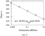
- FIG. 4 plots the major axis diameter DO1 (mm) of oval cavity 20 versus the EFL (%) for the cases corresponding to curves C2, C4 and C5 of FIG. 3 .
- fiber 50 is Corning SMF-28E fiber
- m( ⁇ ) ⁇ 170 it is preferred that an increase in the major axis diameter DO1 for oval cavity 20 is balanced with the attenuation loss and EFL(%).
- drop cables are intended for use in either ducts, direct burial, or aerial applications that subject the cable to various loads and environmental conditions.
- forming a low-cost drop cable 10 involves balancing cost savings with the necessary performance requirements that take into account the environmental conditions under which the drop cable is likely to be used.
- FIG. 6 plots the EFL (%) versus the longitudinal cable strength (kilo-Newtons, kN) for a 150 ft self-supported span of drop cable under National Electrical Safety Code (NESC) heavy ice and wind loading conditions for three different parameters: fiber strain S at operating load (%) as represented by curves CA, the low-temperature limits of attenuation ⁇ as represented by curves CB, and the relative cost of drop cable 10 as represented by curves CC.
- the values for the low-temperature attenuation ⁇ have not been fixed for this example and precise thermal limits have not been calculated, but the general form is provided on the plot for illustration.
- the lower curve CB represents the attenuation limit for a standard fiber while the upper curve CB is for a bend-insensitive fiber.
- the longitudinal cable strength on the x-axis corresponds to the diameters D 30 of the two strength members 30 so that a decrease/increase in the strength member diameters causes a decrease/increase in the overall diameter and weight of the cable.
- a maximum allowable amount of fiber strain S under load i.e., a maximum strain limit S T
- the strain limit line S T (shown in bold) is preferably not crossed in the direction that exceeds this limit.
- the present disclosure thus includes forming drop cable 10 so that the at least one fiber 50 contained in oval cavity 20 has an amount of strain S in the range 0.25S T ⁇ S ⁇ S T . Also in an example embodiment, (0.001)L ⁇ EFL ⁇ (0.004)L, (i.e., 0.1% ⁇ EFL ⁇ 0.4%).
- oval cavity 20 serves to accommodate the corresponding amount of EFL without having to increase the drop cable size, as would be required in the case of a circular cavity, thereby maintaining a lower cost.
- FIG. 7 is a schematic representation of an exemplary cable manufacturing apparatus ("apparatus") 300 for making low-cost drop cable 10 using methods of the present disclosure.
- Apparatus 300 includes support member payoff units 306 that payoff lengths of support members 30, and a fiber payoff unit 308 that pays off fiber 50.
- Fiber payoff unit 308 may include, for example, one or more rotating wheels (spools) that pay off one or more fibers 50.
- Apparatus 300 illustrates a drop cable manufacturing method that employs a single optical fiber 50, but other numbers, including 2, 4, 6, etc., of optical fibers, or groups of fibers arranged in ribbons, for example, can be used. In example embodiments, other approaches, such as flying off, may also be used to pay off one or more optical fibers 50 and/or support members 30.
- Apparatus 300 also includes tension capstans 310 around which support members 30 are tensioned.
- a load cell 320 is arranged to receive fiber 50 from fiber payoff unit 308 and support members 30 from tension capstans 310 and place them in their proper relative orientation for forming drop cable 10.
- An extruder 350 is arranged downstream of tension capstans 310 and fiber payoff unit 308 and is configured to receive support members 30 and fiber 50 from load cell 320 and combine these elements with an extrusion material 352 (e.g., medium density polyethylene) that forms cable protective cover 12.
- an extrusion material 352 e.g., medium density polyethylene
- tension capstans 310 allow tension to be placed on support members 30 during the extrusion process that takes place in extruder 350. This causes support members 30 to be stretched during the extrusion process as the protective cover extrusion material 352 encompasses the support members and fiber 50.
- Extruder 350 is configured so that extruded material 352 is extruded in a manner that forms oval cavity 20 around fiber 50, as discussed in greater detail below.
- the cable structure formed upon exiting extruder 350 is still hot and is referred to herein as an "uncooled drop cable" 10U.
- Uncooled drop cable 10U needs to be cooled and such cooling is performed immediately downstream of extruder 350 using a cooling device 360.
- cooling device 360 includes a longitudinally extending trough filled with a cooling fluid (not shown) such as liquid water. Cooling device 360 cools the otherwise uncooled drop cable 10U and cooled drop cable 10 exits the cooling device.
- the resultant drop cable 10 passes through a tension-release device 366 (e.g., a "caterpuller") and is then collected on a take-up device 370 such as, for example, a take-up spool.
- a tension-release device 366 e.g., a "caterpuller”
- the one or more fibers 50 of drop cable 10 are subject to controlled tensioning during manufacturing so that an increased tension or strain resides in fiber 50 after drop cable 10 is formed. In an example embodiment, such tension is imparted to the one or more fibers 50 at the fiber payoff step.
- tension capstans 310 serve to elongate (stretch) strength members 30.
- the stretched strength members 30 and strained fiber 50 enter extruder 350, wherein the molten extruding material 352 that forms protective cover 12 is applied.
- tension-relief device 366 the tension-relief device releases the tension in strength members 30, thus causing them to relax.
- protective cover 12 to shrink in length while the length of fiber 50 remains substantially the same.
- the amount of EFL for fiber 50 is set between 0 and 0.4%, more preferably between 0.1% and 0.4%, and even more preferably between 0.2% and 0.4%.
- FIG. 8 is a cross-sectional view of an example embodiment of extruder 350 that contains a tip 410 with a fiber exit end 412 and die 420 with an end
- FIG. 9A is a close-up view of an example configuration for tip 410 and die 420 used to form drop cable 10.
- FIG. 9B is a front-on view of the die 420 showing a single elongate aperture 424 having a major axis A M .
- Extruder 350 includes a combination head 430 that includes a front end 432, sides 433, and a back end 434, wherein the combination head supports tip 410 and die 420 oriented along a first axis AE 1 .
- Die 420 is held in place adjacent front end 432 with a die retainer nut 440.
- a flow diverter 446 is arranged around tip 410 and is configured to divert the flow of extruding material 352. Flow diverter 446 is held to combination head 430 with a flow diverter nut 448 at back end 434.
- Extruder 350 also includes a feed unit 450 arranged along an axis AE 2 perpendicular to axis AE 1 and operably connected to combination head 430 at one of sides 433.
- Feed unit 450 defines a tapered chamber 452 that tapers into a channel 456 at a channel end 458. Channel end 458 connects to flow diverter 446.
- Tapered chamber 452 contains protective cover extrusion material 352, and feed unit 450 is used to feed the heated extrusion material into combination head 430 and through die 420 via the operation of flow diverter 446 and tip 410.
- combination head 430 is a Maillefer combination head available from Maillefer SA, Switzerland.
- protective cover extrusion material 352 is extruded at a temperature TE that is substantially cooler than the normal extrusion temperature used in forming drop cables.
- the cooler temperature allows protective cover extrusion material 352 to better maintain its shape upon extrusion.
- the extrusion temperature TE is in the range 140°C ⁇ TE ⁇ 160°C. This range is about 60°C cooler than the standard extrudate temperature, and increases the melt strength of the extrudate while also reducing the thermal load on fiber 50 during extrusion.
- the spacing between tip 410 and die 420 is such that the fiber exit end 412 of the tip is inside the die, as shown in FIG. 9A .
- This configuration restricts the flow of extrusion material 352 around fiber 50 and gives rise to the formation of oval cavity 20.
- the tip and die spacing is controlled by die retainer nut 440.
- the cooler extrusion material temperature serves to maintain oval cavity 20 until uncooled drop cable 10U is cooled in cooling device 360.
- Surface tension effects cause the initially round central cavity defined by fiber 50 to be pulled into oval cavity 20 in the direction of die aperture major axis A M , which defines the cavity major axis A 1 .
- This transformation of the initially circular cavity defined by fiber 50 into oval cavity 20 is exacerbated upon the cooling of uncooled drop cable 10U, as described above. This obviates the need for a more complex die/tip configuration to form oval cavity 20.
- tip 410 and die 420 are configured to size the gel into an annulus surrounding fiber 50, which, in an example embodiment, has an outer diameter of about 0.45mm. Since the tip/die is round and the cable profile is essentially oval, extrusion material 352 deforms the annulus of the gel on fiber 50 into oval cavity 20 formed in protective cover 12.
- Another example embodiment includes paying off water-blocking material 60 in the form of a water-swellable (e.g., a swell-fleece) yarn.
- the yarn is coated with a SAP, such as a partially cross-linked acrylate.
- water-blocking material 60 includes a gel, a water-swellable yarn, a water-swellable powder (e.g., a SAP powder), or a combination thereof, provided in oval cavity 20 during the extrusion process.
- a water-swellable powder e.g., a SAP powder
- An example method of including a water-swellable powder in a drop cable is disclosed in U.S. Patent Application Serial No. 11/821933, filed on June 26, 2007 , and entitled "Optical Fiber Assemblies Having Relatively Low-Levels of Water-Swellable Powder and Methods Therefor," which patent application is commonly owned and assigned.
- Example fiber optic cables having one or more water-blocking materials are described in U.S. Patent Nos. 4,909,592 and 6,253,012 .
- the diameter DO2 of cavity 20 along minor axis A 2 is as small as about 0.25 mm
- the diameter DO1 along the major axis A 1 is in the range from 0.25 mm to 10 mm.
- the drop cable cross-sectional shape can be round, flat, figure-eight-like, or dumbbell-like (e.g., sextic-like).
- strength members 30 need not have a circular cross-section, but can be, for example, elliptical or oval.
- drop cable 10 can be formed with one or more fibers 50 within cavity 20.
- the one or more fibers 50 can be bend-insensitive fibers, single-mode fibers, multimode fibers, or combinations thereof.
- cavity 20 is defined by an oval buffer tube 26, as shown in FIG. 10 .
- oval buffer tube 26 is included in drop cable 10 by using either a two-step process or by accommodating the buffer tube in the extrusion process discussed above. While buffer tube 26 and protective cover 12 can be formed from the same material, they preferably are formed from different materials so that the protective cover does not bond to the buffer tube.
- the methods of forming drop cable 10 as disclosed herein allow for the formation of a drop cable that has about 40% of the cable cross-sectional area of a typical drop cable, thereby reducing raw material costs significantly.
- the size of strength members is reduced to a diameter of, for example, 1.25mm compared to the more common diameter of 1.6mm.
- the amount and cost of protective cover material used is reduced by about one half.
- the buffering process step is eliminated by feeding the one or more optical fibers directly into the protective cover in a one pass/tubeless operation-with or without a filling compound (e.g., a gel), with or without providing a water-swellable yarn, and with or without a swell powder (e.g., SAP) powder.
- a filling compound e.g., a gel
- SAP swell powder
- the cavity size is typically small (less than 1 mm in diameter) and the EFL is placed in the cable using the above-described tension and release approach.
- the oval cavity with EFL allows "regular” (i.e., non-bend-insensitive) fibers to meet attenuation performance.
- the oval cavity 20 allows the EFL to take a substantially sinusoidal path with a larger amplitude and a lower radius of curvature as compared to a circular cavity of the same cross-sectional area.
- the smaller drop cable size also allows for easier storage of coiled drop cables.
- a distribution cable to the connection site e.g., a home or office
- tens of different drop cable sizes are stocked.
- NIDs Current Network Interface Devices
- a drop cable formed using the present methods having a 40% reduced cross-sectional area can be coiled and placed in an NID at a much longer length, e.g., approximately 200 feet in the same 'box' as a 50 foot conventional drop cable.
- the number of part numbers stocked can be reduced to from about 3 to 5 versus about 10 to 15 for the typical drop cable.
- the weight of the cable is reduced from about 4.3 pounds to about 1.5 pounds for a 200-foot coil. This results in lower shipping and handling costs.
Landscapes
- Physics & Mathematics (AREA)
- General Physics & Mathematics (AREA)
- Optics & Photonics (AREA)
- Engineering & Computer Science (AREA)
- Manufacturing & Machinery (AREA)
- Insulated Conductors (AREA)
- Extrusion Moulding Of Plastics Or The Like (AREA)
- Light Guides In General And Applications Therefor (AREA)
Claims (5)
- Procédé de formation d'un câble de jonction ayant une longueur L et une forme de section transversale allongée, comprenant :l'extrusion d'un matériau de recouvrement protecteur (352) ayant une température d'extrusion TE définie par 140 °C ≤ TE ≤ 160 °C à travers une matrice (420) présentant une ouverture unique qui définit la forme de section transversale allongée du câble pour recouvrir un premier et un deuxième élément de renfort (30) de chaque côté d'au moins une fibre optique (50) et former une cavité ovale (20) ayant un axe majeur et un axe central (A1, AC) et qui entoure l'au moins une fibre optique (50), sachant que le premier et le deuxième élément de renfort (30) se situent sensiblement le long de l'axe majeur (A1) de la cavité (20) ;la mise en tension du premier et du deuxième élément de renfort (30) pendant ladite extrusion ; etla cessation de la mise en tension après ladite extrusion pour réduire la longueur du câble de jonction et faire en sorte que l'au moins une fibre optique (50) adopte une configuration en serpentin sensiblement dans un plan défini par les axes majeur et central (A1, AC).
- Le procédé de la revendication 1, sachant que la configuration en serpentin est sensiblement sinusoïdale.
- Le procédé de la revendication 1 ou 2, sachant que, en comparaison avec la longueur de câble de jonction L, l'au moins une fibre optique (50) a une quantité de longueur de fibre excédentaire (EFL) de : (0,001)L ≤ EFL ≤ (0,004)L.
- Le procédé de l'une quelconque des revendications 1 à 3, sachant que l'au moins une fibre optique (50) a une limite d'élasticité ST, et une quantité de contrainte S où (0,25)ST ≤ S ≤ ST.
- Le procédé de l'une quelconque des revendications 1 à 4, sachant que la forme de section transversale allongée est sensiblement ovale.
Priority Applications (1)
| Application Number | Priority Date | Filing Date | Title |
|---|---|---|---|
| PL09175029T PL2184630T3 (pl) | 2008-11-05 | 2009-11-04 | Sposób wytwarzania kabla odgałęźnego mającego owalną wnękę |
Applications Claiming Priority (1)
| Application Number | Priority Date | Filing Date | Title |
|---|---|---|---|
| US12/290,931 US20100109174A1 (en) | 2008-11-05 | 2008-11-05 | Method for drop cable having an oval cavity |
Publications (2)
| Publication Number | Publication Date |
|---|---|
| EP2184630A1 EP2184630A1 (fr) | 2010-05-12 |
| EP2184630B1 true EP2184630B1 (fr) | 2019-10-02 |
Family
ID=41647279
Family Applications (1)
| Application Number | Title | Priority Date | Filing Date |
|---|---|---|---|
| EP09175029.9A Not-in-force EP2184630B1 (fr) | 2008-11-05 | 2009-11-04 | Procédé de fabrication d'un cable pour le branchement d'abonné doté d'une cavité ovale |
Country Status (4)
| Country | Link |
|---|---|
| US (2) | US20100109174A1 (fr) |
| EP (1) | EP2184630B1 (fr) |
| AU (2) | AU2009230761A1 (fr) |
| PL (1) | PL2184630T3 (fr) |
Families Citing this family (13)
| Publication number | Priority date | Publication date | Assignee | Title |
|---|---|---|---|---|
| RU2488859C2 (ru) * | 2008-06-25 | 2013-07-27 | Зм Инновейтив Пропертиз Компани | Система доступа абонентского места к линиям связи при горизонтальной прокладке кабеля в многоквартирном доме и способ ее установки |
| BRPI0923970A2 (pt) * | 2009-03-27 | 2016-01-19 | 3M Innovative Properties Co | dutos de sustentação para um sistema local de acesso de cabo de transmissão para cabeamento horizontal nas aplicações destinadas às unidades com moradores múltiplos |
| EP2411853A1 (fr) * | 2009-03-27 | 2012-02-01 | 3M Innovative Properties Company | Système de point d'entrée pour le branchement d'une fibre à faible encombrement et procédé d'installation |
| EP2462668A2 (fr) | 2009-08-06 | 2012-06-13 | 3M Innovative Properties Company | Conduites adhésives pour applications de câblage |
| AU2011240990B2 (en) | 2010-04-14 | 2015-04-02 | 3M Innovative Properties Company | Removable adhesive backed ducts for cabling and a removal method |
| US9097870B2 (en) * | 2010-05-19 | 2015-08-04 | Adc Telecommunications, Inc. | Rapid multi-service terminal |
| FR2998978B1 (fr) * | 2012-12-04 | 2016-02-12 | Acome Soc Cooperative Et Participative Sa Cooperative De Production A Capital Variable | Cable optique et procede de fabrication d'un cable optique associe |
| US9075212B2 (en) * | 2013-09-24 | 2015-07-07 | Corning Optical Communications LLC | Stretchable fiber optic cable |
| ES2966734T3 (es) * | 2015-06-26 | 2024-04-24 | Prysmian Spa | Un cable óptico de micromódulo aéreo |
| JP2017116860A (ja) * | 2015-12-25 | 2017-06-29 | 三菱電線工業株式会社 | 光ファイバケーブルの製造方法、及び光ファイバケーブル |
| US11187863B2 (en) | 2017-09-11 | 2021-11-30 | Prysmian S.P.A | Flat optical drop cable |
| WO2022264310A1 (fr) * | 2021-06-16 | 2022-12-22 | 日本電信電話株式会社 | Procédé de pose de câble optique |
| CN115083699B (zh) * | 2021-11-30 | 2023-04-25 | 广东欢联电子科技有限公司 | 一种耐低温抗干扰通讯线缆生产工艺 |
Family Cites Families (24)
| Publication number | Priority date | Publication date | Assignee | Title |
|---|---|---|---|---|
| CA1103494A (fr) * | 1976-06-24 | 1981-06-23 | Dennis L. Lewis | Cables a fibres optiques, et methode de fabrication connexe |
| GB1486764A (en) * | 1976-07-27 | 1977-09-21 | Standard Telephones Cables Ltd | Cable |
| US4199225A (en) * | 1978-04-07 | 1980-04-22 | Bicc Limited | Optical guides |
| US4420220A (en) * | 1979-06-25 | 1983-12-13 | Bicc Public Limited Company | Optical guides |
| JPS57165804A (en) * | 1981-04-06 | 1982-10-13 | Nippon Telegr & Teleph Corp <Ntt> | Manufacture of pipe-containing optical fiber cord |
| US4909592A (en) * | 1988-09-29 | 1990-03-20 | American Telephone And Telegraph Company, At&T Bell Laboratories | Communication cable having water blocking provisions in core |
| JPH03282683A (ja) * | 1990-03-30 | 1991-12-12 | Hitachi Ltd | ノイズ量に自動的に適応するパターン検出方法および装置 |
| US5125063A (en) * | 1990-11-08 | 1992-06-23 | At&T Bell Laboratories | Lightweight optical fiber cable |
| US5249249A (en) * | 1991-08-27 | 1993-09-28 | Siecor Corporation | Cable utilizing multiple light waveguide stacks |
| US5574816A (en) * | 1995-01-24 | 1996-11-12 | Alcatel Na Cable Sytems, Inc. | Polypropylene-polyethylene copolymer buffer tubes for optical fiber cables and method for making the same |
| US6487347B2 (en) * | 1997-03-24 | 2002-11-26 | Corning Cable Systems Llc | Indoor/outdoor optical cables |
| US6563990B1 (en) * | 1998-06-22 | 2003-05-13 | Corning Cable Systems, Llc | Self-supporting cables and an apparatus and methods for making the same |
| US6253012B1 (en) * | 1998-11-12 | 2001-06-26 | Alcatel | Cycled fiber lock for cross-functional totally dry optical fiber loose tube cable |
| US6215931B1 (en) * | 1999-01-26 | 2001-04-10 | Alcatel | Flexible thermoplastic polyolefin elastomers for buffering transmission elements in a telecommunications cable |
| US6314224B1 (en) * | 1999-06-18 | 2001-11-06 | Alcatel | Thick-walled cable jacket with non-circular cavity cross section |
| FR2809499B1 (fr) * | 2000-05-29 | 2003-10-03 | Cit Alcatel | Peau de protection pour fibres optiques |
| FR2810747B1 (fr) * | 2000-06-23 | 2002-12-20 | Acome Soc Coop Travailleurs | Cable optique a accessibilite continue |
| SE522788C2 (sv) * | 2002-03-20 | 2004-03-09 | Ericsson Telefon Ab L M | Förfarande och anordning för anordnade av optofiber |
| US20090190890A1 (en) * | 2002-12-19 | 2009-07-30 | Freeland Riley S | Fiber optic cable having a dry insert and methods of making the same |
| US7415181B2 (en) * | 2005-07-29 | 2008-08-19 | Corning Cable Systems Llc | Fiber optic cables and assemblies for fiber to the subscriber applications |
| US7277615B2 (en) * | 2002-12-19 | 2007-10-02 | Corning Cable Systems, Llc. | Fiber optic cable having a dry insert and methods of making the same |
| CN101061407B (zh) * | 2004-09-27 | 2010-04-28 | 普雷斯曼电缆及系统能源有限公司 | 抗水性光缆和制造方法 |
| US7599589B2 (en) * | 2005-07-20 | 2009-10-06 | Draka Comteq B.V. | Gel-free buffer tube with adhesively coupled optical element |
| US7272289B2 (en) * | 2005-09-30 | 2007-09-18 | Corning Incorporated | Low bend loss optical fiber |
-
2008
- 2008-11-05 US US12/290,931 patent/US20100109174A1/en not_active Abandoned
-
2009
- 2009-10-26 AU AU2009230761A patent/AU2009230761A1/en active Pending
- 2009-10-26 AU AU2009101358A patent/AU2009101358A4/en not_active Expired
- 2009-11-04 PL PL09175029T patent/PL2184630T3/pl unknown
- 2009-11-04 EP EP09175029.9A patent/EP2184630B1/fr not_active Not-in-force
-
2014
- 2014-06-25 US US14/314,797 patent/US9329351B2/en not_active Expired - Fee Related
Non-Patent Citations (1)
| Title |
|---|
| None * |
Also Published As
| Publication number | Publication date |
|---|---|
| AU2009101358A4 (en) | 2011-12-01 |
| US20150301296A1 (en) | 2015-10-22 |
| EP2184630A1 (fr) | 2010-05-12 |
| US9329351B2 (en) | 2016-05-03 |
| AU2009230761A1 (en) | 2010-05-20 |
| PL2184630T3 (pl) | 2020-06-15 |
| US20100109174A1 (en) | 2010-05-06 |
Similar Documents
| Publication | Publication Date | Title |
|---|---|---|
| EP2184630B1 (fr) | Procédé de fabrication d'un cable pour le branchement d'abonné doté d'une cavité ovale | |
| RU177028U1 (ru) | Система оплеточной пленки | |
| US12554086B2 (en) | Optical communication cable | |
| US6785450B2 (en) | Self-supporting fiber optic cable | |
| US6356690B1 (en) | Self-supporting fiber optic cable | |
| CN104937466B (zh) | 用于光纤电缆的束缚膜 | |
| US6744954B1 (en) | Submarine optical cable, optical fiber unit employed in the submarine optical cable, and method of making optical fiber unit | |
| US9091830B2 (en) | Binder film for a fiber optic cable | |
| US9250410B2 (en) | Optical fiber cable and interconnect assembly | |
| US9075212B2 (en) | Stretchable fiber optic cable | |
| US7221831B2 (en) | Multi-tube fiber optic cable and system and method for making the same | |
| CN105899988A (zh) | 具有套筒的光纤电缆 | |
| US9927590B2 (en) | Composite film for a fiber optic cable | |
| US9354414B2 (en) | Drop cable assembly | |
| US20220269024A1 (en) | Optical fiber cable with drop cables having preattached optical connectors and method to strand the same |
Legal Events
| Date | Code | Title | Description |
|---|---|---|---|
| PUAI | Public reference made under article 153(3) epc to a published international application that has entered the european phase |
Free format text: ORIGINAL CODE: 0009012 |
|
| AK | Designated contracting states |
Kind code of ref document: A1 Designated state(s): AT BE BG CH CY CZ DE DK EE ES FI FR GB GR HR HU IE IS IT LI LT LU LV MC MK MT NL NO PL PT RO SE SI SK SM TR |
|
| AX | Request for extension of the european patent |
Extension state: AL BA RS |
|
| 17P | Request for examination filed |
Effective date: 20101110 |
|
| 17Q | First examination report despatched |
Effective date: 20101207 |
|
| STAA | Information on the status of an ep patent application or granted ep patent |
Free format text: STATUS: EXAMINATION IS IN PROGRESS |
|
| GRAP | Despatch of communication of intention to grant a patent |
Free format text: ORIGINAL CODE: EPIDOSNIGR1 |
|
| STAA | Information on the status of an ep patent application or granted ep patent |
Free format text: STATUS: GRANT OF PATENT IS INTENDED |
|
| INTG | Intention to grant announced |
Effective date: 20190405 |
|
| GRAS | Grant fee paid |
Free format text: ORIGINAL CODE: EPIDOSNIGR3 |
|
| GRAA | (expected) grant |
Free format text: ORIGINAL CODE: 0009210 |
|
| STAA | Information on the status of an ep patent application or granted ep patent |
Free format text: STATUS: THE PATENT HAS BEEN GRANTED |
|
| AK | Designated contracting states |
Kind code of ref document: B1 Designated state(s): AT BE BG CH CY CZ DE DK EE ES FI FR GB GR HR HU IE IS IT LI LT LU LV MC MK MT NL NO PL PT RO SE SI SK SM TR |
|
| RAP1 | Party data changed (applicant data changed or rights of an application transferred) |
Owner name: CORNING OPTICAL COMMUNICATIONS LLC |
|
| REG | Reference to a national code |
Ref country code: GB Ref legal event code: FG4D |
|
| REG | Reference to a national code |
Ref country code: CH Ref legal event code: EP Ref country code: AT Ref legal event code: REF Ref document number: 1186835 Country of ref document: AT Kind code of ref document: T Effective date: 20191015 |
|
| REG | Reference to a national code |
Ref country code: DE Ref legal event code: R096 Ref document number: 602009059997 Country of ref document: DE |
|
| REG | Reference to a national code |
Ref country code: IE Ref legal event code: FG4D |
|
| REG | Reference to a national code |
Ref country code: NL Ref legal event code: MP Effective date: 20191002 |
|
| REG | Reference to a national code |
Ref country code: LT Ref legal event code: MG4D |
|
| REG | Reference to a national code |
Ref country code: AT Ref legal event code: MK05 Ref document number: 1186835 Country of ref document: AT Kind code of ref document: T Effective date: 20191002 |
|
| PG25 | Lapsed in a contracting state [announced via postgrant information from national office to epo] |
Ref country code: ES Free format text: LAPSE BECAUSE OF FAILURE TO SUBMIT A TRANSLATION OF THE DESCRIPTION OR TO PAY THE FEE WITHIN THE PRESCRIBED TIME-LIMIT Effective date: 20191002 Ref country code: AT Free format text: LAPSE BECAUSE OF FAILURE TO SUBMIT A TRANSLATION OF THE DESCRIPTION OR TO PAY THE FEE WITHIN THE PRESCRIBED TIME-LIMIT Effective date: 20191002 Ref country code: SE Free format text: LAPSE BECAUSE OF FAILURE TO SUBMIT A TRANSLATION OF THE DESCRIPTION OR TO PAY THE FEE WITHIN THE PRESCRIBED TIME-LIMIT Effective date: 20191002 Ref country code: LV Free format text: LAPSE BECAUSE OF FAILURE TO SUBMIT A TRANSLATION OF THE DESCRIPTION OR TO PAY THE FEE WITHIN THE PRESCRIBED TIME-LIMIT Effective date: 20191002 Ref country code: BG Free format text: LAPSE BECAUSE OF FAILURE TO SUBMIT A TRANSLATION OF THE DESCRIPTION OR TO PAY THE FEE WITHIN THE PRESCRIBED TIME-LIMIT Effective date: 20200102 Ref country code: FI Free format text: LAPSE BECAUSE OF FAILURE TO SUBMIT A TRANSLATION OF THE DESCRIPTION OR TO PAY THE FEE WITHIN THE PRESCRIBED TIME-LIMIT Effective date: 20191002 Ref country code: PT Free format text: LAPSE BECAUSE OF FAILURE TO SUBMIT A TRANSLATION OF THE DESCRIPTION OR TO PAY THE FEE WITHIN THE PRESCRIBED TIME-LIMIT Effective date: 20200203 Ref country code: NO Free format text: LAPSE BECAUSE OF FAILURE TO SUBMIT A TRANSLATION OF THE DESCRIPTION OR TO PAY THE FEE WITHIN THE PRESCRIBED TIME-LIMIT Effective date: 20200102 Ref country code: GR Free format text: LAPSE BECAUSE OF FAILURE TO SUBMIT A TRANSLATION OF THE DESCRIPTION OR TO PAY THE FEE WITHIN THE PRESCRIBED TIME-LIMIT Effective date: 20200103 Ref country code: LT Free format text: LAPSE BECAUSE OF FAILURE TO SUBMIT A TRANSLATION OF THE DESCRIPTION OR TO PAY THE FEE WITHIN THE PRESCRIBED TIME-LIMIT Effective date: 20191002 Ref country code: NL Free format text: LAPSE BECAUSE OF FAILURE TO SUBMIT A TRANSLATION OF THE DESCRIPTION OR TO PAY THE FEE WITHIN THE PRESCRIBED TIME-LIMIT Effective date: 20191002 |
|
| PG25 | Lapsed in a contracting state [announced via postgrant information from national office to epo] |
Ref country code: HR Free format text: LAPSE BECAUSE OF FAILURE TO SUBMIT A TRANSLATION OF THE DESCRIPTION OR TO PAY THE FEE WITHIN THE PRESCRIBED TIME-LIMIT Effective date: 20191002 Ref country code: IS Free format text: LAPSE BECAUSE OF FAILURE TO SUBMIT A TRANSLATION OF THE DESCRIPTION OR TO PAY THE FEE WITHIN THE PRESCRIBED TIME-LIMIT Effective date: 20200224 Ref country code: CZ Free format text: LAPSE BECAUSE OF FAILURE TO SUBMIT A TRANSLATION OF THE DESCRIPTION OR TO PAY THE FEE WITHIN THE PRESCRIBED TIME-LIMIT Effective date: 20191002 |
|
| REG | Reference to a national code |
Ref country code: CH Ref legal event code: PL |
|
| REG | Reference to a national code |
Ref country code: DE Ref legal event code: R097 Ref document number: 602009059997 Country of ref document: DE |
|
| PG2D | Information on lapse in contracting state deleted |
Ref country code: IS |
|
| PG25 | Lapsed in a contracting state [announced via postgrant information from national office to epo] |
Ref country code: LI Free format text: LAPSE BECAUSE OF NON-PAYMENT OF DUE FEES Effective date: 20191130 Ref country code: RO Free format text: LAPSE BECAUSE OF FAILURE TO SUBMIT A TRANSLATION OF THE DESCRIPTION OR TO PAY THE FEE WITHIN THE PRESCRIBED TIME-LIMIT Effective date: 20191002 Ref country code: EE Free format text: LAPSE BECAUSE OF FAILURE TO SUBMIT A TRANSLATION OF THE DESCRIPTION OR TO PAY THE FEE WITHIN THE PRESCRIBED TIME-LIMIT Effective date: 20191002 Ref country code: CH Free format text: LAPSE BECAUSE OF NON-PAYMENT OF DUE FEES Effective date: 20191130 Ref country code: DK Free format text: LAPSE BECAUSE OF FAILURE TO SUBMIT A TRANSLATION OF THE DESCRIPTION OR TO PAY THE FEE WITHIN THE PRESCRIBED TIME-LIMIT Effective date: 20191002 Ref country code: LU Free format text: LAPSE BECAUSE OF NON-PAYMENT OF DUE FEES Effective date: 20191104 Ref country code: MC Free format text: LAPSE BECAUSE OF FAILURE TO SUBMIT A TRANSLATION OF THE DESCRIPTION OR TO PAY THE FEE WITHIN THE PRESCRIBED TIME-LIMIT Effective date: 20191002 Ref country code: IS Free format text: LAPSE BECAUSE OF FAILURE TO SUBMIT A TRANSLATION OF THE DESCRIPTION OR TO PAY THE FEE WITHIN THE PRESCRIBED TIME-LIMIT Effective date: 20200202 |
|
| PLBE | No opposition filed within time limit |
Free format text: ORIGINAL CODE: 0009261 |
|
| STAA | Information on the status of an ep patent application or granted ep patent |
Free format text: STATUS: NO OPPOSITION FILED WITHIN TIME LIMIT |
|
| REG | Reference to a national code |
Ref country code: BE Ref legal event code: MM Effective date: 20191130 |
|
| PG25 | Lapsed in a contracting state [announced via postgrant information from national office to epo] |
Ref country code: SK Free format text: LAPSE BECAUSE OF FAILURE TO SUBMIT A TRANSLATION OF THE DESCRIPTION OR TO PAY THE FEE WITHIN THE PRESCRIBED TIME-LIMIT Effective date: 20191002 Ref country code: SM Free format text: LAPSE BECAUSE OF FAILURE TO SUBMIT A TRANSLATION OF THE DESCRIPTION OR TO PAY THE FEE WITHIN THE PRESCRIBED TIME-LIMIT Effective date: 20191002 |
|
| 26N | No opposition filed |
Effective date: 20200703 |
|
| PG25 | Lapsed in a contracting state [announced via postgrant information from national office to epo] |
Ref country code: IE Free format text: LAPSE BECAUSE OF NON-PAYMENT OF DUE FEES Effective date: 20191104 |
|
| PG25 | Lapsed in a contracting state [announced via postgrant information from national office to epo] |
Ref country code: BE Free format text: LAPSE BECAUSE OF NON-PAYMENT OF DUE FEES Effective date: 20191130 Ref country code: SI Free format text: LAPSE BECAUSE OF FAILURE TO SUBMIT A TRANSLATION OF THE DESCRIPTION OR TO PAY THE FEE WITHIN THE PRESCRIBED TIME-LIMIT Effective date: 20191002 |
|
| PG25 | Lapsed in a contracting state [announced via postgrant information from national office to epo] |
Ref country code: CY Free format text: LAPSE BECAUSE OF FAILURE TO SUBMIT A TRANSLATION OF THE DESCRIPTION OR TO PAY THE FEE WITHIN THE PRESCRIBED TIME-LIMIT Effective date: 20191002 |
|
| PG25 | Lapsed in a contracting state [announced via postgrant information from national office to epo] |
Ref country code: HU Free format text: LAPSE BECAUSE OF FAILURE TO SUBMIT A TRANSLATION OF THE DESCRIPTION OR TO PAY THE FEE WITHIN THE PRESCRIBED TIME-LIMIT; INVALID AB INITIO Effective date: 20091104 Ref country code: MT Free format text: LAPSE BECAUSE OF FAILURE TO SUBMIT A TRANSLATION OF THE DESCRIPTION OR TO PAY THE FEE WITHIN THE PRESCRIBED TIME-LIMIT Effective date: 20191002 |
|
| PGFP | Annual fee paid to national office [announced via postgrant information from national office to epo] |
Ref country code: PL Payment date: 20210928 Year of fee payment: 13 |
|
| PGFP | Annual fee paid to national office [announced via postgrant information from national office to epo] |
Ref country code: GB Payment date: 20211028 Year of fee payment: 13 Ref country code: DE Payment date: 20211013 Year of fee payment: 13 |
|
| PGFP | Annual fee paid to national office [announced via postgrant information from national office to epo] |
Ref country code: IT Payment date: 20211117 Year of fee payment: 13 Ref country code: FR Payment date: 20211025 Year of fee payment: 13 |
|
| PG25 | Lapsed in a contracting state [announced via postgrant information from national office to epo] |
Ref country code: TR Free format text: LAPSE BECAUSE OF FAILURE TO SUBMIT A TRANSLATION OF THE DESCRIPTION OR TO PAY THE FEE WITHIN THE PRESCRIBED TIME-LIMIT Effective date: 20191002 |
|
| PG25 | Lapsed in a contracting state [announced via postgrant information from national office to epo] |
Ref country code: MK Free format text: LAPSE BECAUSE OF FAILURE TO SUBMIT A TRANSLATION OF THE DESCRIPTION OR TO PAY THE FEE WITHIN THE PRESCRIBED TIME-LIMIT Effective date: 20191002 |
|
| REG | Reference to a national code |
Ref country code: DE Ref legal event code: R119 Ref document number: 602009059997 Country of ref document: DE |
|
| GBPC | Gb: european patent ceased through non-payment of renewal fee |
Effective date: 20221104 |
|
| PG25 | Lapsed in a contracting state [announced via postgrant information from national office to epo] |
Ref country code: IT Free format text: LAPSE BECAUSE OF NON-PAYMENT OF DUE FEES Effective date: 20221104 Ref country code: GB Free format text: LAPSE BECAUSE OF NON-PAYMENT OF DUE FEES Effective date: 20221104 Ref country code: DE Free format text: LAPSE BECAUSE OF NON-PAYMENT OF DUE FEES Effective date: 20230601 |
|
| PG25 | Lapsed in a contracting state [announced via postgrant information from national office to epo] |
Ref country code: FR Free format text: LAPSE BECAUSE OF NON-PAYMENT OF DUE FEES Effective date: 20221130 |
|
| PG25 | Lapsed in a contracting state [announced via postgrant information from national office to epo] |
Ref country code: PL Free format text: LAPSE BECAUSE OF NON-PAYMENT OF DUE FEES Effective date: 20221104 |