EP2184656B1 - Steuerung einer mit einer Aktuator-Sensor-Schnittstelle kompatiblen Vorrichtung mithilfe einer ferngesteuerten intelligenten Vorrichtung - Google Patents
Steuerung einer mit einer Aktuator-Sensor-Schnittstelle kompatiblen Vorrichtung mithilfe einer ferngesteuerten intelligenten Vorrichtung Download PDFInfo
- Publication number
- EP2184656B1 EP2184656B1 EP09173969.8A EP09173969A EP2184656B1 EP 2184656 B1 EP2184656 B1 EP 2184656B1 EP 09173969 A EP09173969 A EP 09173969A EP 2184656 B1 EP2184656 B1 EP 2184656B1
- Authority
- EP
- European Patent Office
- Prior art keywords
- electromagnetic contactor
- master device
- state
- sensor
- slave device
- Prior art date
- Legal status (The legal status is an assumption and is not a legal conclusion. Google has not performed a legal analysis and makes no representation as to the accuracy of the status listed.)
- Not-in-force
Links
Images





Classifications
-
- G—PHYSICS
- G05—CONTROLLING; REGULATING
- G05B—CONTROL OR REGULATING SYSTEMS IN GENERAL; FUNCTIONAL ELEMENTS OF SUCH SYSTEMS; MONITORING OR TESTING ARRANGEMENTS FOR SUCH SYSTEMS OR ELEMENTS
- G05B19/00—Program-control systems
- G05B19/02—Program-control systems electric
- G05B19/04—Program control other than numerical control, i.e. in sequence controllers or logic controllers
- G05B19/042—Program control other than numerical control, i.e. in sequence controllers or logic controllers using digital processors
- G05B19/0421—Multiprocessor system
-
- G—PHYSICS
- G05—CONTROLLING; REGULATING
- G05B—CONTROL OR REGULATING SYSTEMS IN GENERAL; FUNCTIONAL ELEMENTS OF SUCH SYSTEMS; MONITORING OR TESTING ARRANGEMENTS FOR SUCH SYSTEMS OR ELEMENTS
- G05B2219/00—Program-control systems
- G05B2219/30—Nc systems
- G05B2219/31—From computer integrated manufacturing till monitoring
- G05B2219/31118—Universal interface between asi and fieldbus, for any fielddevice
-
- G—PHYSICS
- G05—CONTROLLING; REGULATING
- G05B—CONTROL OR REGULATING SYSTEMS IN GENERAL; FUNCTIONAL ELEMENTS OF SUCH SYSTEMS; MONITORING OR TESTING ARRANGEMENTS FOR SUCH SYSTEMS OR ELEMENTS
- G05B2219/00—Program-control systems
- G05B2219/30—Nc systems
- G05B2219/31—From computer integrated manufacturing till monitoring
- G05B2219/31154—Actuator sensor bus, asi, intelligent actuator, motor, sensor
Definitions
- This invention relates to control of an actuator-sensor-interface (AS-I) compatible device. More particularly, this invention relates a communication network for controlling an actuator sensor interface (AS-I) compatible device using a remote intelligence device.
- AS-I actuator-sensor-interface
- BARRIUSO POY A ET AL "The detector control system of the ATLAS experiment” JOURNAL OF INSTRUMENTATION, INSTITUTE OF PHYSICS PUBLISHING, BRISTOL, GB, Vol. 3, no. 5, 1 May 2008 P05006 discloses implementation of a detector control system.
- a local device i.e., a slave device located at the electromagnetic contactor is equipped with the intelligence to determine the operating state of the electromagnetic contactor, and reports the information to a remote monitoring device (i.e., a master device).
- a remote monitoring device i.e., a master device.
- a remote, centralized intelligence device i.e., a master device
- a device such as an electromechanical device
- An exemplary embodiment of the present invention provides a communication network that includes a master device, an actuator-sensor-interface (AS-I) communication bus, a device configured to be monitored and controlled, and a slave device in communication with the master device via the AS-I communication bus.
- the device that is configured to be monitored and controlled is operatively connectable to the slave device, and the slave device is configured to receive commands from the master device via the AS-I communication bus, and to execute the commands to control the device.
- an AS-I communication network 1 that includes a remote intelligence device, i.e., a master device 2, an AS-I communication module i.e., a slave device 3 in communication with the master device 2 via an AS-I communication bus 4.
- the AS-I communication network 1 further includes a display unit 5 connected to the master device 2 via a converter 6, for example.
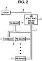
- FIG. 2 is an AS-I communication network according to another exemplary embodiment of the present invention.
- the AS-I communication network 1 includes a plurality of slave devices 3 in communication with one master device 2.
- the number of slave devices 3 may vary, which in an embodiment is up to a maximum of 62 slave devices per master device 2. However, since the maximum number of slave devices is design dependent, it will be appreciated that the scope of the invention is not limited to a particular maximum number.
- the AS-I communication network 1 further includes a device to be monitored and controlled, for example, an electromagnetic contactor (as depicted in FIGS. 3 and 4 , for example) operatively connected to the slave device 3.
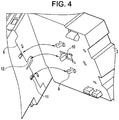
- the slave device 3 is configured to receive commands from the master device 2 via the AS-I communication bus 4, and to execute the commands to control the device. The connection between the device and the slave device 3 will now be described with reference to FIGS. 3 and 4 .
- the slave device 3 is connected with a device such as an electromagnetic contactor 8.
- a device such as an electromagnetic contactor 8.
- the present invention is not limited to being applied to an electromagnetic contactor, and any suitable AS-I compatible device may be used, for example, an overload relay.
- the device is one of an electrical device, an electromechanical device or an electromagnetic device, for example.
- the slave device 3 according to one embodiment of the present invention includes a plurality of hooks 9 and an AS-I latch 10.
- the slave device 3 is connected with the electromagnetic contactor 8 via the hooks 9 which are inserted into grooves 11 of the electromagnetic contactor 8.
- the AS-I latch 10 of the slave device 3 is inserted into a slot of a movable contact carrier 12 of the electromagnetic contactor 8. Addition details concerning the movable contact carrier 12 are described below with reference to FIG. 5 .
- FIG. 5 is a fragmentary cross sectional diagram according to one embodiment of the present invention illustrating the movable contact carrier 12 of the electromagnetic contactor 8.
- the movable contact carrier 12 includes a contact opening 13 in each pole in which a movable contact 14 is positioned (three poles for a three-phase device for example), and biased against a lower edge of the opening 13 by a spring 15.
- the movable contact 14 aligns with a fixed contact 17 (as depicted in FIG. 3 ) when in the closed position.
- the movable contact carrier 12 is attached to a movable armature 18, which cooperates with a fixed core 19 by energization of a coil 20 that creates a magnetic flux through the fixed core 19 and movable armature 18 and across an air gap.
- a spring 16 biases the movable armature 18 and movable contact carrier 12 away from the fixed core 19, while the energized coil 20 biases the movable contact carrier 12 toward the fixed core 19, thereby separating or enabling contact between the movable contact 14 and the fixed contact 17.
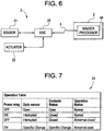
- FIG. 6 is a block diagram illustrating a master device 2 and a slave device 3 according to an exemplary embodiment of the present invention.
- the master device 2 includes a master processor 40 (to be described later with reference to FIG. 7 ).
- the slave device 3 includes a sensor 21, an actuator 22, and a slave processor 23 such as an application specific integrated circuit (ASIC) responsive to computer executable instructions to establish a communication channel between the sensor 21, the actuator 22 and the master device 2.
- ASIC application specific integrated circuit
- the slave device 3 is configured to receive commands from the master device 2 via the AS-I communication bus 4, and to control the electromagnetic contactor 8 based on the commands received from the master device 2.
- the master device 2 sends a command to the slave device 3 via the AS-I communication bus 4 to turn on the electromagnetic contactor 8.
- the slave device 3 receives the command from the master device 2 and energizes the actuator 22 to actuate the electromagnetic contactor 8. Further discussion on the control aspects of the communication system will be discussed later in reference to FIGS. 7-9 .
- the actuator 22 is a power relay that closes to connect a main power (not shown) to the coil 20 of the electromagnetic contactor 8 to cause the movable contact carrier 12 of the electromagnetic contactor 8 to move into an energized position and in turn to close the movable contacts 14 of the electromagnetic contactor 8.
- the sensor 21 senses a signal representative of the movement of the movable contact carrier 12.
- the sensor 21 may sense other parameters such as voltage, current, pressure or temperature of the electromagnetic contactor 8, for example.
- the slave device 3 sends the sensed signal to the master device 2 indicating whether the movable contact carrier 12 has moved.
- the sensor 21 is an optical sensor.
- the present invention is not limited hereto, and any measuring device suitable for the purposes disclosed herein may be used.
- the signal detected by the sensor 21 may be a flow detection signal, or any type of transducer signal (e.g., a digital signal).
- the master device 2 Based on the signal received from the slave device 3, the master device 2 identifies an operating state of the electromagnetic contactor 8 using an algorithm to be described below in reference to FIG. 7 .
- FIG. 7 is an operation table used by the master device 2 for detecting an operating state of the electromagnetic contactor 8, for example.
- the master device 2 includes a master processor 40 (as depicted in FIG. 6 ) which utilizes an algorithm corresponding to the operation table 24 to determine an operating state of the electromagnetic contactor 8 based on the sensed signal. That is, the operation table 24 includes parameters which are used to determine an operating state of the electromagnetic contactor 8. According to the present invention, the parameters of the operation table 24 may vary dependent upon the type of device being monitored and controlled by the master device 2. According to one embodiment, the master device 2 identifies an operating state of the electromagnetic contactor 8 based on the sensed signal received from the slave device 3.
- the operating state of the electromagnetic contactor 8 is one of a normal state, an abnormal closed state such as a contact weld state where the electromagnetic contactor 8 is closed when it is supposed to be open, or an abnormal open state such as a coil burn state where the electromagnetic contactor 8 is open when it is supposed to be closed.
- the sensor 21 senses a movement (i.e., an opening action) of the movable contact carrier 12, and the contacts 14 are open, the master device 2 determines that the electromagnetic contactor 8 is operating in a normal state.
- the master device 2 determines that the electromagnetic contactor 8 is operating in a normal state.
- the master device 2 determines that the electromagnetic contactor 8 is in an abnormal closed state.
- the slave device 3 sends a signal back to the master device 2 and the master device 2 determines that the electromagnetic contactor 8 is in an abnormal open state and the electromagnetic contactor 8 is considered to be inoperable.
- the master device 2 when the master device 2 determines that the electromagnetic contactor 8 is in an abnormal open state, the master device 2 promptly (within approximately 10 milliseconds for example) sends a signal back to the power relay 22 for the power relay 22 to go into an off state, in order to protect the coil 20 of the magnetic contactor 8. That is, if the movement of the movable contact carrier 12 of the electromagnetic contactor 8 is not sensed within a specified time period, supply to the coil 20 is terminated.
- the operating state of the electromagnetic contactor 8 as determined by the master device 2 is displayed on the display unit 5 (as depicted in FIGS. 1 and 2 ) to be viewed by a user.
- the AS-I communication network 1 is a subsystem of a communication system as shown in FIG. 8 .
- the communication system 100 may be a supervisory control and data acquisition communication system, for example.
- the communication system 100 includes a personal computer (PC) 25 at an office level, interfacing with an Ethernet/Gateway 26, a PLC 27, and a PC 28 at a plant level.
- the plant level interfaces with a distributed control level which includes the AS-I communication network 1 according to an exemplary embodiment of the present invention and a gateway 29 communicating with a control valve 30 and cells 32.
- the AS-I communication network 1 includes a plurality of master devices 2 and a plurality of slave devices 3 communicating with the respective master devices 2.
- FIG. 9 is a flowchart illustrating a method of controlling an AS-I compatible device via an AS-I communication network in accordance with an exemplary embodiment of the present invention.
- the master device sends a command to the slave device via an AS-I communication bus, to turn on the device.
- the process moves to operation 202, where the slave device receives the command from the master device and processes the command and energizes an actuator to turn on the device.
- the process moves to operation 204 where the sensor of the slave device senses a signal representative of a parameter of the device. For example, if the device is an electromagnetic contactor, for example, the sensor senses a movement of the movable contact carrier of the electromagnetic contactor.
- the process moves to operation 206, where the master device identifies an operating state of the device and controls the device based on the operating state identified. For example, if the master device determines that the device is in an abnormal operating state, the master device sends a signal back to the slave device to de-energize the actuator, thereby de-energizing the device. For example, when the device is an electromagnetic contactor, if the master device determines that the electromagnetic contactor is in an abnormal closed state (e.g., a contact weld state) or an abnormal open state (e.g., a coil burn state), the master device sends a signal back to the slave device to de-energize the actuator, thereby de-energizing the electromagnetic contactor. From operation 206, the process moves to operation 208, where the operating state of the device is displayed via a display unit.
- an abnormal closed state e.g., a contact weld state
- an abnormal open state e.g., a coil burn state
- the master device is capable of determining the operating status of an AS-I compatible device such as an electrical device, an electromechanical device or an electromagnetic device, for example, operatively connectable to a slave device, and controlling the device, which provides the benefits of lower manufacturing costs and greater accessibility.
- AS-I compatible device such as an electrical device, an electromechanical device or an electromagnetic device, for example, operatively connectable to a slave device, and controlling the device, which provides the benefits of lower manufacturing costs and greater accessibility.
Landscapes
- Physics & Mathematics (AREA)
- General Physics & Mathematics (AREA)
- Engineering & Computer Science (AREA)
- Automation & Control Theory (AREA)
- Selective Calling Equipment (AREA)
- Switch Cases, Indication, And Locking (AREA)
Claims (5)
- Kommunikationsnetz (1) umfassend:eine Master-Vorrichtung (2);einen Aktuator-Sensor-Schnittstellen(AS-I)-Kommunikationsbus (4);ein elektromagnetisches Schütz (8), das konfiguriert ist, um überwacht und gesteuert zu werden;eine Slave-Vorrichtung (3), die mit der Master-Vorrichtung (2) über den Aktuator-Sensor-Schnittstellen(AS-I)-Kommunikationsbus (4) verbunden ist, wobei das elektromagnetische Schütz (8) konfiguriert ist, um mit der Slave-Vorrichtung (3) wirkverbindbar überwacht und gesteuert zu werden, und die Slave-Vorrichtung (3) konfiguriert ist, um Befehle von der Master-Vorrichtung (2) über den AS-I-Kommunikationsbus (4) zu empfangen und die Befehle zum Steuern des elektromagnetischen Schützes (8) auszuführen;ein Leistungsrelais (22), das zum Betätigen des elektromagnetischen Schützes (8) angeordnet und konfiguriert ist;einen Sensor (21), der angeordnet und konfiguriert ist, um ein Signal abzutasten, das eine Bewegung eines beweglichen Kontaktträgers (12) des elektromagnetischen Schützes (8) als Reaktion auf die Betätigung des elektromagnetischen Schützes (8) darstellt, wobei der Sensor (21) konfiguriert ist, um das abgetastete Signal an die Slave-Vorrichtung (3) zu senden, und die Slave-Vorrichtung angeordnet ist, um das abgetastete Signal an die Master-Vorrichtung (2) zu senden;wobei die Master-Vorrichtung (2) konfiguriert ist, um einen Befehl an die Slave-Vorrichtung (3) zu senden, der die Slave-Vorrichtung (3) anweist, das elektromagnetische Schütz (8) zu betätigen,wobei die Master-Vorrichtung (2) konfiguriert ist, um einen Betriebszustand des elektromagnetischen Schützes (8) basierend auf dem abgetasteten Signal zu bestimmen, wobei der Betriebszustand des elektromagnetischen Schützes einer von einem Normalzustand, einem anormalen geschlossenen Zustand oder einem anormalen offenen Zustand ist, wobei die Master-Vorrichtung (2) bestimmt, dass sich das elektromagnetische Schütz (8) im normalen Betriebszustand befindet, wenn (i) wenn sich das Leistungsrelais (22) in einem Aus-Zustand befindet, das abgetastete Signal eine Öffnungsaktion des beweglichen Kontaktträgers (12) anzeigt und (ii) wenn das Leistungsrelais (22) in einem Ein-Zustand ist, das abgetastete Signal anzeigt, dass die Bewegung des beweglichen Kontaktträgers (12) unterbrochen ist, undwobei, wenn die Master-Vorrichtung bestimmt, dass sich das elektromagnetische Schütz (8) im anormalen geschlossenen Zustand oder im anormalen geöffneten Zustand befindet, die Master-Vorrichtung (2) innerhalb einer vorbestimmten Zeitspanne ein Signal an das Leistungsrelais (22) sendet, um in den Aus-Zustand zu wechseln, wodurch das elektromagnetische Schütz (8) entregt wird.
- Kommunikationsnetz (1) nach Anspruch 1, wobei die Slave-Vorrichtung (3) eine Vielzahl von Slave-Vorrichtungen (3) umfasst und das elektromagnetische Schütz (8) eine Vielzahl von elektromagnetischen Schützen (8) umfasst, wobei jedes elektromagnetische Schütz (8) mit einer entsprechenden Slave-Vorrichtung (3) der Vielzahl von Slave-Vorrichtungen (3) wirkverbunden ist.
- Kommunikationsnetz (1) nach Anspruch 1 oder Anspruch 2, ferner umfassend:
eine Anzeigeeinheit (5), die mit der Master-Vorrichtung (2) verbindbar und konfiguriert ist, um den Betriebszustand des elektromagnetischen Schützes (8) anzuzeigen. - Kommunikationsnetz nach einem der vorstehenden Ansprüche, wobei der Sensor (21) ein optischer Sensor ist.
- Verfahren zum Steuern eines elektromagnetischen Schützes (8) über ein Aktuator-Sensor-Schnittstellen(AS-I)-Kommunikationsnetzwerk, wobei das Verfahren Folgendes umfasst:Wirkverbinden einer Slave-Vorrichtung (3) mit dem zu steuernden und zu überwachenden elektromagnetischen Schütz (8);Senden von Befehlen durch eine Master-Vorrichtung (2) an die Slave-Vorrichtung (3) über einen Aktuator-Sensor-Schnittstellen(AS-I)-Kommunikationsbus (4);Ausführen der Befehle über die Slave-Vorrichtung (3) zum Steuern des elektromagnetischen Schützes (8);wobei das Ausführen der Befehle über die Slave-Vorrichtung (3) ein Betätigen des elektromagnetischen Schützes (8) über ein Leistungsrelais (22) beinhaltet;Abtasten eines Signals, das eine Bewegung eines beweglichen Kontaktträgers (12) des elektromagnetischen Schützes (8) über einen Sensor (21) als Reaktion auf das Betätigen des elektromagnetischen Schützes (8) darstellt;Senden des abgetasteten Signals vom Sensor (21) an die Master-Vorrichtung (2) über die Slave-Vorrichtung (3) und den Aktor-Sensor-Schnittstellen-(AS-I)-Kommunikationsbus (4);Bestimmen eines Betriebszustandes des elektromagnetischen Schützes (8) mit der Master-Vorrichtung (2) basierend auf dem abgetasteten Signal, wobei der Betriebszustand des elektromagnetischen Schützes einer von einem Normalzustand, einem anormalen geschlossenen Zustand oder einem anormalen offenen Zustand ist, wobei die Master-Vorrichtung (2) bestimmt, dass sich das elektromagnetische Schütz (8) im normalen Betriebszustand befindet, wenn (i) wenn sich das Leistungsrelais (22) in einem Aus-Zustand befindet, das abgetastete Signal eine Öffnungsaktion des beweglichen Kontaktträgers (12) anzeigt und (ii) wenn das Leistungsrelais (22) in einem Ein-Zustand ist, das abgetastete Signal anzeigt, dass die Bewegung des beweglichen Kontaktträgers (12) unterbrochen ist; undBestimmen, ob sich ein beweglicher Kontaktträger (12) des elektromagnetischen Schützes (8) im anormalen geschlossenen Zustand oder im anormalen geöffneten Zustand befindet und, wenn ja, innerhalb einer vorbestimmten Zeitspanne, Senden eines Signal durch die Master-Vorrichtung (2) an das Leistungsrelais (22), um in den Aus-Zustand zu wechseln, wodurch das elektromagnetische Schütz (8) entregt wird.
Applications Claiming Priority (1)
| Application Number | Priority Date | Filing Date | Title |
|---|---|---|---|
| US12/265,267 US7802037B2 (en) | 2008-11-05 | 2008-11-05 | Control of an actuator-sensor-interface compatible device using a remote intelligence device |
Publications (2)
| Publication Number | Publication Date |
|---|---|
| EP2184656A1 EP2184656A1 (de) | 2010-05-12 |
| EP2184656B1 true EP2184656B1 (de) | 2019-06-19 |
Family
ID=41647213
Family Applications (1)
| Application Number | Title | Priority Date | Filing Date |
|---|---|---|---|
| EP09173969.8A Not-in-force EP2184656B1 (de) | 2008-11-05 | 2009-10-23 | Steuerung einer mit einer Aktuator-Sensor-Schnittstelle kompatiblen Vorrichtung mithilfe einer ferngesteuerten intelligenten Vorrichtung |
Country Status (3)
| Country | Link |
|---|---|
| US (1) | US7802037B2 (de) |
| EP (1) | EP2184656B1 (de) |
| CN (1) | CN101738965B (de) |
Families Citing this family (4)
| Publication number | Priority date | Publication date | Assignee | Title |
|---|---|---|---|---|
| EP2642811B1 (de) * | 2012-03-23 | 2014-11-26 | Siemens Aktiengesellschaft | Vorrichtung sowie Verfahren zum Festlegen eines Übertragungskanals eines Slaves |
| KR101343447B1 (ko) | 2012-06-11 | 2013-12-20 | 엘에스산전 주식회사 | 모터 스타터 시스템 및 이의 동작방법 |
| EP2778811A1 (de) * | 2013-03-15 | 2014-09-17 | Siemens Aktiengesellschaft | Vorrichtung für ein AS-Interface System |
| CN104360618B (zh) * | 2014-11-20 | 2017-04-12 | 杰瑞石油天然气工程有限公司 | 一种电机控制系统 |
Family Cites Families (15)
| Publication number | Priority date | Publication date | Assignee | Title |
|---|---|---|---|---|
| DE4133636A1 (de) | 1991-10-11 | 1993-04-15 | Lawrenz Wolfhard | Steuerungsbaustein |
| FR2732523B1 (fr) * | 1995-04-03 | 1997-04-25 | Schneider Electric Sa | Module d'interface entre un bus de terrain et un appareillage electrique de commande et de protection d'un moteur electrique |
| US20040194101A1 (en) | 1997-08-21 | 2004-09-30 | Glanzer David A. | Flexible function blocks |
| US6826590B1 (en) | 1996-08-23 | 2004-11-30 | Fieldbus Foundation | Block-oriented control system on high speed ethernet |
| DE19716137C1 (de) * | 1997-04-17 | 1998-10-22 | Siemens Ag | Modul zum Anschluß von Aktoren und/oder Sensoren |
| FR2763180B1 (fr) * | 1997-05-09 | 1999-06-04 | Schneider Electric Sa | Procede et appareil de commande d'un depart-moteur communiquant avec un bus |
| EP1001506B1 (de) * | 1998-11-09 | 2003-02-26 | STMicroelectronics S.r.l. | Schaltung zur digitalen Signalerkennung insbesondere für System mit ASI-Feldbus |
| DE19925552A1 (de) * | 1999-06-04 | 2000-12-07 | Leuze Electronic Gmbh & Co | Sicherheitsschalteranordnung |
| US6446202B1 (en) * | 1999-10-04 | 2002-09-03 | Fisher-Rosemount Systems, Inc. | Process control configuration system for use with an AS-Interface device network |
| GB0213197D0 (en) * | 2002-06-10 | 2002-07-17 | Cnh Belgium Nv | Vehicle control system and apparatus therefor |
| US6963814B2 (en) * | 2002-12-23 | 2005-11-08 | Siemens Energy & Automation, Inc. | Systems, devices, and methods for acceptance testing a fieldbus component configuration program |
| US7246194B2 (en) * | 2003-01-30 | 2007-07-17 | Rosemount, Inc. | Interface module for use with a fieldbus device network and with internet and non-internet based process control networks |
| DE102004030767A1 (de) * | 2004-06-25 | 2006-01-19 | Siemens Ag | AS-Interface-Netzwerk für große Entfernungen |
| US7624219B2 (en) * | 2007-08-09 | 2009-11-24 | Ifm Electronic Gmbh | Bus node |
| CN101221438A (zh) * | 2008-01-11 | 2008-07-16 | 四川航空工业川西机器厂 | 大型等静压机电气控制工作站 |
-
2008
- 2008-11-05 US US12/265,267 patent/US7802037B2/en active Active
-
2009
- 2009-10-23 EP EP09173969.8A patent/EP2184656B1/de not_active Not-in-force
- 2009-11-05 CN CN200910211846.9A patent/CN101738965B/zh active Active
Non-Patent Citations (1)
| Title |
|---|
| None * |
Also Published As
| Publication number | Publication date |
|---|---|
| CN101738965B (zh) | 2014-10-22 |
| CN101738965A (zh) | 2010-06-16 |
| US7802037B2 (en) | 2010-09-21 |
| EP2184656A1 (de) | 2010-05-12 |
| US20100115166A1 (en) | 2010-05-06 |
Similar Documents
| Publication | Publication Date | Title |
|---|---|---|
| EP3740958B1 (de) | Kontaktor mit kontaktträgerpositionserfassung | |
| US5754387A (en) | Method of monitoring contactor operation | |
| CN101813750B (zh) | 接触器磨损老化检测装置及方法 | |
| KR101266047B1 (ko) | 스마트 콘센트를 이용한 전력 모니터링 시스템 | |
| EP2184656B1 (de) | Steuerung einer mit einer Aktuator-Sensor-Schnittstelle kompatiblen Vorrichtung mithilfe einer ferngesteuerten intelligenten Vorrichtung | |
| JP4237061B2 (ja) | スイッチ装置の制御及び保護モジュール | |
| CN111434600B (zh) | 用于电梯系统的远程监控系统及远程监控电梯系统的方法 | |
| EP3051555B1 (de) | Relaiseinheit, steuerungsverfahren für relaiseinheit | |
| CN102328887B (zh) | 电梯的制动器控制装置 | |
| WO2009024168A1 (en) | Apparatus and method for monitoring an electromagnetic brake | |
| JP6773226B2 (ja) | 自動化システムの電気機械コンポーネントをモニタリングするための方法 | |
| CN110114850B (zh) | 有载抽头变换器和制造有载抽头变换器的方法 | |
| US20190371551A1 (en) | Method and device for diagnosing wear of an electrical switching unit, and electrical unit comprising such a device | |
| CN112186507B (zh) | 一种智能化开关柜一键式顺序控制方法 | |
| CN104396138A (zh) | 电动机启动器系统及用于使电动机启动器系统工作的方法 | |
| CN104885023A (zh) | 虚拟限位开关 | |
| US9263207B2 (en) | Switch device | |
| CN209641614U (zh) | 一种复合型开关 | |
| CN102854869A (zh) | 监控系统和刮板机 | |
| CN107359613B (zh) | 车库三相动力电源智能控制系统及方法 | |
| CN102190247B (zh) | 液压先导控制系统及设有该系统的液压先导起重机 | |
| KR101742024B1 (ko) | 전력 관제 방법 및 전력 관제 시스템 | |
| EP1215792B1 (de) | Verbesserte Steuervorrichtung und entsprechendes Verfahren | |
| CN105785264B (zh) | 断路器状态监测装置 | |
| CN105045088A (zh) | 用于安全操作技术设备的安全控制装置及其操作方法 |
Legal Events
| Date | Code | Title | Description |
|---|---|---|---|
| PUAI | Public reference made under article 153(3) epc to a published international application that has entered the european phase |
Free format text: ORIGINAL CODE: 0009012 |
|
| AK | Designated contracting states |
Kind code of ref document: A1 Designated state(s): AT BE BG CH CY CZ DE DK EE ES FI FR GB GR HR HU IE IS IT LI LT LU LV MC MK MT NL NO PL PT RO SE SI SK SM TR |
|
| 17P | Request for examination filed |
Effective date: 20101112 |
|
| 17Q | First examination report despatched |
Effective date: 20101214 |
|
| STAA | Information on the status of an ep patent application or granted ep patent |
Free format text: STATUS: EXAMINATION IS IN PROGRESS |
|
| GRAP | Despatch of communication of intention to grant a patent |
Free format text: ORIGINAL CODE: EPIDOSNIGR1 |
|
| STAA | Information on the status of an ep patent application or granted ep patent |
Free format text: STATUS: GRANT OF PATENT IS INTENDED |
|
| RAP1 | Party data changed (applicant data changed or rights of an application transferred) |
Owner name: ABB SCHWEIZ AG |
|
| INTG | Intention to grant announced |
Effective date: 20190226 |
|
| GRAS | Grant fee paid |
Free format text: ORIGINAL CODE: EPIDOSNIGR3 |
|
| GRAA | (expected) grant |
Free format text: ORIGINAL CODE: 0009210 |
|
| STAA | Information on the status of an ep patent application or granted ep patent |
Free format text: STATUS: THE PATENT HAS BEEN GRANTED |
|
| AK | Designated contracting states |
Kind code of ref document: B1 Designated state(s): AT BE BG CH CY CZ DE DK EE ES FI FR GB GR HR HU IE IS IT LI LT LU LV MC MK MT NL NO PL PT RO SE SI SK SM TR |
|
| REG | Reference to a national code |
Ref country code: GB Ref legal event code: FG4D |
|
| REG | Reference to a national code |
Ref country code: CH Ref legal event code: EP |
|
| REG | Reference to a national code |
Ref country code: IE Ref legal event code: FG4D |
|
| REG | Reference to a national code |
Ref country code: DE Ref legal event code: R096 Ref document number: 602009058774 Country of ref document: DE |
|
| REG | Reference to a national code |
Ref country code: AT Ref legal event code: REF Ref document number: 1146292 Country of ref document: AT Kind code of ref document: T Effective date: 20190715 |
|
| REG | Reference to a national code |
Ref country code: NL Ref legal event code: MP Effective date: 20190619 |
|
| PG25 | Lapsed in a contracting state [announced via postgrant information from national office to epo] |
Ref country code: FI Free format text: LAPSE BECAUSE OF FAILURE TO SUBMIT A TRANSLATION OF THE DESCRIPTION OR TO PAY THE FEE WITHIN THE PRESCRIBED TIME-LIMIT Effective date: 20190619 Ref country code: HR Free format text: LAPSE BECAUSE OF FAILURE TO SUBMIT A TRANSLATION OF THE DESCRIPTION OR TO PAY THE FEE WITHIN THE PRESCRIBED TIME-LIMIT Effective date: 20190619 Ref country code: SE Free format text: LAPSE BECAUSE OF FAILURE TO SUBMIT A TRANSLATION OF THE DESCRIPTION OR TO PAY THE FEE WITHIN THE PRESCRIBED TIME-LIMIT Effective date: 20190619 Ref country code: NO Free format text: LAPSE BECAUSE OF FAILURE TO SUBMIT A TRANSLATION OF THE DESCRIPTION OR TO PAY THE FEE WITHIN THE PRESCRIBED TIME-LIMIT Effective date: 20190919 Ref country code: LT Free format text: LAPSE BECAUSE OF FAILURE TO SUBMIT A TRANSLATION OF THE DESCRIPTION OR TO PAY THE FEE WITHIN THE PRESCRIBED TIME-LIMIT Effective date: 20190619 |
|
| REG | Reference to a national code |
Ref country code: LT Ref legal event code: MG4D |
|
| PG25 | Lapsed in a contracting state [announced via postgrant information from national office to epo] |
Ref country code: GR Free format text: LAPSE BECAUSE OF FAILURE TO SUBMIT A TRANSLATION OF THE DESCRIPTION OR TO PAY THE FEE WITHIN THE PRESCRIBED TIME-LIMIT Effective date: 20190920 Ref country code: BG Free format text: LAPSE BECAUSE OF FAILURE TO SUBMIT A TRANSLATION OF THE DESCRIPTION OR TO PAY THE FEE WITHIN THE PRESCRIBED TIME-LIMIT Effective date: 20190919 Ref country code: LV Free format text: LAPSE BECAUSE OF FAILURE TO SUBMIT A TRANSLATION OF THE DESCRIPTION OR TO PAY THE FEE WITHIN THE PRESCRIBED TIME-LIMIT Effective date: 20190619 |
|
| REG | Reference to a national code |
Ref country code: AT Ref legal event code: MK05 Ref document number: 1146292 Country of ref document: AT Kind code of ref document: T Effective date: 20190619 |
|
| PG25 | Lapsed in a contracting state [announced via postgrant information from national office to epo] |
Ref country code: RO Free format text: LAPSE BECAUSE OF FAILURE TO SUBMIT A TRANSLATION OF THE DESCRIPTION OR TO PAY THE FEE WITHIN THE PRESCRIBED TIME-LIMIT Effective date: 20190619 Ref country code: SK Free format text: LAPSE BECAUSE OF FAILURE TO SUBMIT A TRANSLATION OF THE DESCRIPTION OR TO PAY THE FEE WITHIN THE PRESCRIBED TIME-LIMIT Effective date: 20190619 Ref country code: PT Free format text: LAPSE BECAUSE OF FAILURE TO SUBMIT A TRANSLATION OF THE DESCRIPTION OR TO PAY THE FEE WITHIN THE PRESCRIBED TIME-LIMIT Effective date: 20191021 Ref country code: NL Free format text: LAPSE BECAUSE OF FAILURE TO SUBMIT A TRANSLATION OF THE DESCRIPTION OR TO PAY THE FEE WITHIN THE PRESCRIBED TIME-LIMIT Effective date: 20190619 Ref country code: EE Free format text: LAPSE BECAUSE OF FAILURE TO SUBMIT A TRANSLATION OF THE DESCRIPTION OR TO PAY THE FEE WITHIN THE PRESCRIBED TIME-LIMIT Effective date: 20190619 Ref country code: AT Free format text: LAPSE BECAUSE OF FAILURE TO SUBMIT A TRANSLATION OF THE DESCRIPTION OR TO PAY THE FEE WITHIN THE PRESCRIBED TIME-LIMIT Effective date: 20190619 Ref country code: CZ Free format text: LAPSE BECAUSE OF FAILURE TO SUBMIT A TRANSLATION OF THE DESCRIPTION OR TO PAY THE FEE WITHIN THE PRESCRIBED TIME-LIMIT Effective date: 20190619 |
|
| PG25 | Lapsed in a contracting state [announced via postgrant information from national office to epo] |
Ref country code: IT Free format text: LAPSE BECAUSE OF FAILURE TO SUBMIT A TRANSLATION OF THE DESCRIPTION OR TO PAY THE FEE WITHIN THE PRESCRIBED TIME-LIMIT Effective date: 20190619 Ref country code: ES Free format text: LAPSE BECAUSE OF FAILURE TO SUBMIT A TRANSLATION OF THE DESCRIPTION OR TO PAY THE FEE WITHIN THE PRESCRIBED TIME-LIMIT Effective date: 20190619 Ref country code: SM Free format text: LAPSE BECAUSE OF FAILURE TO SUBMIT A TRANSLATION OF THE DESCRIPTION OR TO PAY THE FEE WITHIN THE PRESCRIBED TIME-LIMIT Effective date: 20190619 Ref country code: IS Free format text: LAPSE BECAUSE OF FAILURE TO SUBMIT A TRANSLATION OF THE DESCRIPTION OR TO PAY THE FEE WITHIN THE PRESCRIBED TIME-LIMIT Effective date: 20191019 |
|
| PG25 | Lapsed in a contracting state [announced via postgrant information from national office to epo] |
Ref country code: TR Free format text: LAPSE BECAUSE OF FAILURE TO SUBMIT A TRANSLATION OF THE DESCRIPTION OR TO PAY THE FEE WITHIN THE PRESCRIBED TIME-LIMIT Effective date: 20190619 |
|
| PG25 | Lapsed in a contracting state [announced via postgrant information from national office to epo] |
Ref country code: PL Free format text: LAPSE BECAUSE OF FAILURE TO SUBMIT A TRANSLATION OF THE DESCRIPTION OR TO PAY THE FEE WITHIN THE PRESCRIBED TIME-LIMIT Effective date: 20190619 Ref country code: DK Free format text: LAPSE BECAUSE OF FAILURE TO SUBMIT A TRANSLATION OF THE DESCRIPTION OR TO PAY THE FEE WITHIN THE PRESCRIBED TIME-LIMIT Effective date: 20190619 |
|
| REG | Reference to a national code |
Ref country code: DE Ref legal event code: R119 Ref document number: 602009058774 Country of ref document: DE |
|
| PG25 | Lapsed in a contracting state [announced via postgrant information from national office to epo] |
Ref country code: IS Free format text: LAPSE BECAUSE OF FAILURE TO SUBMIT A TRANSLATION OF THE DESCRIPTION OR TO PAY THE FEE WITHIN THE PRESCRIBED TIME-LIMIT Effective date: 20200224 Ref country code: MC Free format text: LAPSE BECAUSE OF FAILURE TO SUBMIT A TRANSLATION OF THE DESCRIPTION OR TO PAY THE FEE WITHIN THE PRESCRIBED TIME-LIMIT Effective date: 20190619 |
|
| REG | Reference to a national code |
Ref country code: CH Ref legal event code: PL |
|
| PLBE | No opposition filed within time limit |
Free format text: ORIGINAL CODE: 0009261 |
|
| STAA | Information on the status of an ep patent application or granted ep patent |
Free format text: STATUS: NO OPPOSITION FILED WITHIN TIME LIMIT |
|
| PG2D | Information on lapse in contracting state deleted |
Ref country code: IS |
|
| PG25 | Lapsed in a contracting state [announced via postgrant information from national office to epo] |
Ref country code: LU Free format text: LAPSE BECAUSE OF NON-PAYMENT OF DUE FEES Effective date: 20191023 Ref country code: DE Free format text: LAPSE BECAUSE OF NON-PAYMENT OF DUE FEES Effective date: 20200501 Ref country code: CH Free format text: LAPSE BECAUSE OF NON-PAYMENT OF DUE FEES Effective date: 20191031 Ref country code: LI Free format text: LAPSE BECAUSE OF NON-PAYMENT OF DUE FEES Effective date: 20191031 |
|
| 26N | No opposition filed |
Effective date: 20200603 |
|
| REG | Reference to a national code |
Ref country code: BE Ref legal event code: MM Effective date: 20191031 |
|
| PG25 | Lapsed in a contracting state [announced via postgrant information from national office to epo] |
Ref country code: BE Free format text: LAPSE BECAUSE OF NON-PAYMENT OF DUE FEES Effective date: 20191031 Ref country code: SI Free format text: LAPSE BECAUSE OF FAILURE TO SUBMIT A TRANSLATION OF THE DESCRIPTION OR TO PAY THE FEE WITHIN THE PRESCRIBED TIME-LIMIT Effective date: 20190619 |
|
| GBPC | Gb: european patent ceased through non-payment of renewal fee |
Effective date: 20191023 |
|
| PG25 | Lapsed in a contracting state [announced via postgrant information from national office to epo] |
Ref country code: IE Free format text: LAPSE BECAUSE OF NON-PAYMENT OF DUE FEES Effective date: 20191023 Ref country code: GB Free format text: LAPSE BECAUSE OF NON-PAYMENT OF DUE FEES Effective date: 20191023 Ref country code: FR Free format text: LAPSE BECAUSE OF NON-PAYMENT OF DUE FEES Effective date: 20191031 |
|
| PG25 | Lapsed in a contracting state [announced via postgrant information from national office to epo] |
Ref country code: CY Free format text: LAPSE BECAUSE OF FAILURE TO SUBMIT A TRANSLATION OF THE DESCRIPTION OR TO PAY THE FEE WITHIN THE PRESCRIBED TIME-LIMIT Effective date: 20190619 |
|
| PG25 | Lapsed in a contracting state [announced via postgrant information from national office to epo] |
Ref country code: MT Free format text: LAPSE BECAUSE OF FAILURE TO SUBMIT A TRANSLATION OF THE DESCRIPTION OR TO PAY THE FEE WITHIN THE PRESCRIBED TIME-LIMIT Effective date: 20190619 Ref country code: HU Free format text: LAPSE BECAUSE OF FAILURE TO SUBMIT A TRANSLATION OF THE DESCRIPTION OR TO PAY THE FEE WITHIN THE PRESCRIBED TIME-LIMIT; INVALID AB INITIO Effective date: 20091023 |
|
| PG25 | Lapsed in a contracting state [announced via postgrant information from national office to epo] |
Ref country code: MK Free format text: LAPSE BECAUSE OF FAILURE TO SUBMIT A TRANSLATION OF THE DESCRIPTION OR TO PAY THE FEE WITHIN THE PRESCRIBED TIME-LIMIT Effective date: 20190619 |