EP2184823B1 - Support pour plafond - Google Patents
Support pour plafond Download PDFInfo
- Publication number
- EP2184823B1 EP2184823B1 EP20080168815 EP08168815A EP2184823B1 EP 2184823 B1 EP2184823 B1 EP 2184823B1 EP 20080168815 EP20080168815 EP 20080168815 EP 08168815 A EP08168815 A EP 08168815A EP 2184823 B1 EP2184823 B1 EP 2184823B1
- Authority
- EP
- European Patent Office
- Prior art keywords
- opening
- ceiling support
- opening part
- ceiling
- threaded rod
- Prior art date
- Legal status (The legal status is an assumption and is not a legal conclusion. Google has not performed a legal analysis and makes no representation as to the accuracy of the status listed.)
- Not-in-force
Links
Images


Classifications
-
- H—ELECTRICITY
- H02—GENERATION; CONVERSION OR DISTRIBUTION OF ELECTRIC POWER
- H02G—INSTALLATION OF ELECTRIC CABLES OR LINES, OR OF COMBINED OPTICAL AND ELECTRIC CABLES OR LINES
- H02G3/00—Installations of electric cables or lines or protective tubing therefor in or on buildings, equivalent structures or vehicles
- H02G3/30—Installations of cables or lines on walls, floors or ceilings
- H02G3/32—Installations of cables or lines on walls, floors or ceilings using mounting clamps
Definitions
- the invention relates to a mounting of particular cable routing devices serving ceiling support according to the preamble of claim 1.
- Cable routing devices of this type are known, for example, from [1], product catalog of LANZ OENSINGEN AG, April 2003.
- the mounting on the ceiling serving carrier material for cable management devices usually consists of a so-called ceiling support to which a boom (console) is connectable. On the boom connected to the ceiling support, the cable guiding devices are laid down, as shown in [1].
- the [1] known, usually made of galvanized or stainless steel existing ceiling support has an end piece or a top plate, which is welded or screwed to a mostly perforated, rod or tubular profile part.
- This top plate is connected by means of mounting screws or metal dowels, also called segment anchor, with the ceiling.
- the segment anchors lowered into the ceiling are able to carry larger loads.
- the boom After mounting the ceiling support, the boom can be screwed to the appropriate height with a side wall of the generally U- or C-shaped profile part, or hung in it.
- the craftsman In order to stably mount the ceiling supports to the ceiling, they are each fastened to the ceiling with one or more appropriately sized segment anchors.
- the craftsman To install the ceiling support, the craftsman usually climbs a ladder, after which the ceiling support is held with one hand. With the other hand, the craftsman must place a nut on the at least one segment anchor and, for safety's sake, screw it up a few turns in order to provisionally mount or fix the ceiling support. Due to the relatively high weight of the ceiling support to be held, the often unfavorable position of the craftsman on the ladder, often bad lighting on construction sites and the often great cold, which leads to clammy fingers, this assembly is associated with significant problems, especially security problems. Hand injuries have occurred during the described manipulation with floor supports, injuries due to lateral deflection or falling down of the ceiling support. Normally, the craftsman on the ladder is also unsecured.
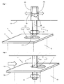
- EP 1 962 401 A2 is the one in the Figures 1 and 2 shown ceiling support 1 ', which has a support body 12 in the form of a rectangular profile, which is provided at the top with a plate-shaped end piece 11 and a top plate.
- FIG. 1 a dowel or segment anchor 2, which is fastened in a hole 91 in a ceiling 9.
- Segment anchors of this type are for example from [3], DE 197 56 997 A1 known.
- the segment anchor 2 shown has a head piece 29, which is held by a threaded rod 21 and which bears against the end piece 261 of a sleeve 26 is pulled and pushes this radially outward, whereby the segment anchor 2 is anchored in the bore 91.
- On the underside of the threaded rod 21 is provided with a nut 25.
- a receiving opening 111 is provided, which serves to receive the screw nut 25 provided with the threaded rod 21.
- the receiving opening 111 has a larger first and a smaller second opening part 1111 and 1112, respectively.
- the larger first opening part 1111 is dimensioned such that the threaded rod 21 and the connecting element or nut 25 fastened thereto can be guided.
- the smaller second opening portion 1112 is dimensioned such that the threaded rod 21 is inserted therein with little play, when the ceiling support 1 'is displaced laterally accordingly.
- the diameter of the nut 25 is also chosen to be substantially larger than the diameter of the second opening portion 1112.
- the present invention is therefore based on the object to provide a further improved ceiling support which is mounted by means of at least two anchored in a ceiling mounting elements, such as threaded rods.
- a ceiling support is to create, which is independent of any possibly high weight and possibly larger dimensions, easy and quick to assemble without security risks and can no longer solve automatically after the provisional connection with the anchored in the ceiling threaded rods under force ,
- the ceiling support which is used in particular the installation of a cable guide device, has a preferably plate-shaped end piece and an adjoining support body, which is connectable to a boom on which the load to be supported can be stored.
- the end piece can be connected to at least one first and one second threaded rod, which are anchored in the ceiling.
- the end piece is provided with at least two receiving openings, each having a larger first opening portion into which a rotatably mounted on the first and second threaded rod connecting element is inserted, and having a smaller for holding the connecting element second opening part, in which the inserted threaded rod is displaceable, with the distance is chosen larger than the distance between the threaded rods between the first opening parts.
- the inventive ceiling support can therefore be connected in a few steps with the first and second threaded rod, with a later automatic release of the ceiling support is practically avoided by the threaded rods even under the action of force.
- the connecting elements such as nuts, placed on the anchored in the ceiling threaded rods.
- the first threaded rod with the attached connecting element is passed through the first opening part of the first receiving opening and moved so far into the second opening part of the first receiving opening until the second threaded rod inserted with the attached connecting element in the first opening part of the second receiving opening and in the second opening part the second receiving opening can be moved.
- the ceiling support can be solved by simply moving the threaded rods.
- the fasteners or nuts are tightened.
- the ceiling support is held stable in the sequence of two threaded rods and suitable for carrying larger loads.
- the assembly process can be divided into two steps, which can be performed independently by the craftsman.
- the craftsman can form-fitting and inventive ceiling support in the first step with the existing in the ceiling segment anchors so that it can be connected to a crash-proof design without the need for tools or fasteners. It is only necessary that the threaded rods are inserted sequentially into the receiving openings, which is possible by displacement and / or rotation.
- the ceiling support can be fixed without tightening it by tightening the connecting elements, if necessary the nut.
- the distance between the first opening parts is selected to be greater than the distance between the threaded rods, it is virtually impossible that the ceiling support can be released from the threaded rods again.
- the receiving openings can be configured differently and aligned.
- the second opening parts of the two receiving openings extend in a first preferred embodiment perpendicular or obliquely to each other.
- first threaded rod is inserted into the first opening part of the first receiving opening and displaced into the second opening part until the second threaded rod can be inserted into the first opening part of the second receiving opening and moved into the second opening part there.
- the second opening part of the second receiving opening preferably runs along the line of a circle, the center of which points through the mounting position of the first threaded rod is formed.
- the first threaded rod can therefore be moved to an end position and held stationary there be moved while the second threaded rod, by rotation of the ceiling support in its final position.
- the second opening parts of the two receiving openings extend at a distance parallel to one another, which preferably corresponds to the distance between the two threaded rods.
- the first threaded rod is inserted into the first opening part of the first receiving opening and inserted so far into the second opening part until the second threaded rod can be inserted into the first opening part of the first receiving opening and moved into the second opening part.
- the installation of the ceiling support therefore succeeds by a linear back and forth of the ceiling support, which can be easily performed.
- the ceiling support can solve automatically, because in turn at least one forward and backward displacement of the ceiling support is required.
- the second opening part of the first and / or second receiving opening has a winding course.
- the receiving openings are arranged such that the courses of the two second opening parts, starting from the first opening parts, approach steadily, at least at the beginning.
- the two receiving openings therefore have preferably in the region of the first opening parts a maximum distance from each other.
- the first opening parts can therefore be provided peripherally, while the lying in the region of the second opening parts mounting positions can be provided at desired locations.
- the second opening parts of the receiving openings are preferably dimensioned such that the threaded rods are held laterally inserted and free of play.
- the adjacent to each second opening part edge, which is part of the end piece, serves as a flange for holding the connecting element or the nut.
- connecting elements possibly the nuts
- each a seat is incorporated, which serves as a mounting position and the holding of the connecting element.
- barbs may be provided by means of which the connecting elements are held in the mounting position.
- the Figures 1 and 2 show a known ceiling support 1 ', which has been described above.
- FIG. 3 shows a sectional view of an inventive ceiling support 1, the plate-shaped end piece 11 has two receiving openings of two threaded rods 21A, 21B receiving openings 111A, 111B, each having a first opening portion 1111A and 1111B and an adjoining second opening portion 1112A and 1112B.
- the receiving openings 111A, 111B according to the invention ceiling support 1 therefore preferably have the shape of a keyhole, wherein the second opening part 1112A and 1112B, which corresponds to the beard of the virtual key, may have different preferably gradients.
- the distance d2 is substantially smaller than the distance d1 between the first opening portions 1111A, 1111B of the two receiving openings 111A, 111B. It is therefore not possible to insert the two threaded rods 21A, 21B simultaneously into the associated first opening parts 111A, 111B.
- FIG. 3 That is, first, the first screw rod 21A with the first screw nut 25A has been inserted into the first receiving hole 111A through the first opening part 1111A and shifted therein to the second opening part 1112A until the second screw rod 21B overlies the first opening part 1111B of the second receiving hole B stands.
- the second threaded rod 21B provided with the second nut 25B is inserted into the first opening portion 1111B of the second receiving opening 111B and slid into the second opening portion 1112B.
- the second opening parts 1112A, 1112B are perpendicular to each other. As long as the second threaded rod 21B dwells in the second opening part 1112B of the second receiving opening 111B, the first threaded rod 21A provided with the first screw nut 25 can not be released from the first receiving opening 111A.
- the second opening parts 1112A, 1112B each have a seat 112A, 112B, which are preferably machined in the form of a recess adapted to the nuts 25A, 25B in the bottom 119 of the end piece 11 , Due to the weight of the ceiling support 1, the nuts 25A, 25B are therefore pressed into and held by the seat 112A, 112B. An automatic displacement of the ceiling support 1 is therefore further prevented by this measure.
- each seat 112A, 112B is formed as a collar-shaped edge which is embossed or milled into the end piece 11 in such a way that it closely encloses and holds the associated screw nut 25A, 25B so that it can only be rotated by means of a tool.
- FIG. 3 It can also be seen that the first threaded rod 21A in the second opening portion 1112A of the first receiving opening 111A shifts when the second threaded rod 21B is inserted into the second opening portion 1112B of the second receiving opening 111B.
- the second opening part 1112B of the second receiving opening 111B becomes Preferably aligned along the line k of a circle whose center is located at the mounting position of the first threaded rod 21A.
- the second opening portion 1112A of the first receiving opening 111A may be relatively narrow in this case.
- the ceiling support can only be released by means of a manipulation that can be carried out practically only by the installer. By contrast, it is not possible for random forces to release the ceiling support 1 again.
- FIG. 4 shows the ceiling support 1 of FIG. 3 with a preferably configured second receiving opening 111B, whose second opening part 1112B extends in a first section perpendicular to the second opening part 1112A of the first receiving opening 111A and in a second section parallel, preferably coaxial thereto.
- each receiving opening may also be connected to two or more first opening parts 1111B, 1111B '. This can be helpful if the ceiling support 1 is to be installed in an area where there is little room for tampering.
- FIGS. 5a-b show sectional views of an inventive ceiling support 1, the end piece 11 has two receiving openings of two threaded rods 21A, 21B receiving openings 111A, 111B, the second opening portions 1112A, 1112B at a distance d2 of the threaded rods 21A, 21B parallel to each other.
- the two receiving openings 111A, 111B have between their first opening parts 1111A, 1111B again the maximum distance d1, which is greater than the distance d2 between the threaded rods 21A, 21B. It is therefore not possible in this embodiment of the ceiling support 1, the threaded rods 21A, 21B simultaneously inserted into the receiving openings 111A, 111B or to remove them.
- the first threaded rod 21A provided with the first screw nut 25A has to be inserted into the first opening part 1111A of the first receiving opening 111A and then slid to the end of the second opening part 1112A. In this end position, it is possible to insert the second threaded rod 21B provided with the second nut 25B into the first opening part 1111B of the second receiving opening 111B and to move it into the second opening part 1112B.
- the first threaded rod 21A in the second opening part 1112A of the first receiving opening 111A is moved back so far until both threaded rods 21A, 21B each come to a mounting position on which a recording of the nut 25A and 25B serving seat 112A and 112B is provided ,
- the ceiling support 1 is reliably prevented that this can automatically solve the threaded rods 21A, 21B, since opposing displacements are necessary, which can be easily performed only by the installer.
Landscapes
- Engineering & Computer Science (AREA)
- Architecture (AREA)
- Civil Engineering (AREA)
- Structural Engineering (AREA)
- Connection Of Plates (AREA)
Claims (14)
- Etai de plafond (1) en particulier pour le montage d'un dispositif de guidage de câble (6), avec une pièce d'extrémité (11) et un corps d'étai (12) à raccorder, qui peut être relié à une flèche sur laquelle peut être déposée la charge à porter, la pièce d'extrémité pouvant être reliée à au moins une première et une seconde tige filetée (21A; 21B) qui sont ancrées dans le plafond (9) caractérisé en ce que la pièce d'extrémité (11) est munie d'au moins deux ouvertures de logement (111A, 111B) qui présentent une première partie d'ouverture plus grande (1111A; 1111B), dans lesquelles peut être inséré un élément de liaison (25A; 25B) logé rotatif sur la première respectivement la seconde tige filetée (21A; 21B) et qui présentent une seconde partie d'ouverture plus petite (1112A; 1112B) appropriée pour le maintien de l'élément de liaison (25A; 25B) dans laquelle peut coulisser la tige filetée insérée (21A; 21B), la distance d1 les premières parties d'ouverture (1111A, 1111B) étant sélectionnée plus grande que la distance d2 entre les tiges filetées (21A, 21B).
- Etai de plafond (1) selon la revendication 1, caractérisé en ce que les secondes parties d'ouverture, (1112A; 1112B) des deux ouvertures de logement (111A, 111B) s'étendent perpendiculairement ou obliquement entre elles.
- Etai de plafond (1) selon la revendication 1, caractérisé en ce que les secondes parties d'ouverture, (1112A; 1112B) des deux ouvertures de logement (111A, 111B) s'étendent parallèlement à une distance entre elles qui correspond de préférence à la distance d2 entre les deux tiges filetées (21A, 21B).
- Etai de plafond (1) selon la revendication 2 ou 3, caractérisé en ce que la seconde partie d'ouverture (1112A; 1112B) de la première et/ou seconde ouverture de logement (111A, 111B) présente un tracé rectiligne ou coudé ou en ce que la seconde partie d'ouverture (1112B) est orientée au moins approximativement le long de la ligne d'un cercle qui s'étend autour de la position de montage de la première tige filetée (21A) dans la première ouverture de logement (111A) .
- Etai de plafond (1) selon l'une des revendications 1 à 4, caractérisé en ce que les deux ouvertures de logement (111A, 111B) sont disposées de sorte que les tracés des deux secondes parties ouverture (1112A; 1112B) se rapproche au moins au début constamment en partant des premières parties d'ouverture (1111A; 1111B).
- Etai de plafond (1) selon l'une des revendications 1 à 5, caractérisé en ce que le bord (112A; 122B) se trouvant dans la continuité de la seconde partie d'ouverture plus petite (1112A; 1112B) sert de bride pour l'élément de liaison (25A; 25B).
- Etai de plafond (1) selon la revendication 6, caractérisé en ce que les dimensions de la seconde partie d'ouverture (1112A; 1112B) sont sélectionnées en fonction du diamètre de la tige filetée (21A, 21B) de sorte que celle-ci puissent être maintenue de préférence sans jeu après le montage dans la seconde partie d'ouverture respective (1112A; 1112B).
- Etai de plafond (1) selon la revendication 6 ou 7, caractérisé en ce que dans le bord de la première et/ou de la seconde partie d'ouverture (1112A; 1112B), il est ménagé un siège (112A, 112B) et/ou au moins un contre-crochet (115) au moyen duquel l'élément de liaison (25A; 25B) est maintenu dans la partie d'ouverture (1112A; 1112B) de préférence en position de montage.
- Etai de plafond (1) selon la revendication 8, caractérisé en ce que le siège (112) présente la forme d'un évidement en forme de collerette qui est pressé ou fraisé dans la pièce d'extrémité (11) de sorte qu'il en résulte une modification de hauteur continue ou brusque entre la première partie d'ouverture plus grande (1111A; 1111B) et la seconde partie d'ouverture plus petite (1112A; 1112B).
- Etai de plafond (1) selon l'une des revendications 1 à 9, caractérisé en ce que l'élément de liaison (25) est un écrou ou en ce que l'élément de liaison (25) se compose d'un écrou et d'une rondelle.
- Etai de plafond (1) selon l'une des revendications 1 à 10, caractérisé en ce que l'ouverture de logement (111) présente au moins approximativement la forme d'un trou de serrure.
- Etai de plafond (1) selon l'une des revendications 1 à 11, caractérisé en ce que la pièce d'extrémité (11) est une plaque métallique de préférence affinée et en ce que les tiges filetées (21A, 21B) qui y sont reliées font partie de segments d'ancrage ancrés dans le plafond (9).
- Etai de plafond (1) selon l'une des revendications 1 à 12, caractérisé en ce qu'il est prévu au moins une troisième ouverture de logement et/ou une ouverture de logement qui présente au moins deux premières parties d'ouverture (1111) reliées entre elles par une seconde partie d'ouverture (1112).
- Etai de plafond (1) selon l'une des revendications 1 à 13, caractérisé en ce que l'étai de plafond (1) est reliée à au moins une première et une seconde tige filetée (21A; 21B) ancrées dans le plafond (9).
Priority Applications (2)
| Application Number | Priority Date | Filing Date | Title |
|---|---|---|---|
| DE200850001458 DE502008001458D1 (de) | 2008-11-11 | 2008-11-11 | Deckenstütze |
| EP20080168815 EP2184823B1 (fr) | 2008-11-11 | 2008-11-11 | Support pour plafond |
Applications Claiming Priority (1)
| Application Number | Priority Date | Filing Date | Title |
|---|---|---|---|
| EP20080168815 EP2184823B1 (fr) | 2008-11-11 | 2008-11-11 | Support pour plafond |
Publications (2)
| Publication Number | Publication Date |
|---|---|
| EP2184823A1 EP2184823A1 (fr) | 2010-05-12 |
| EP2184823B1 true EP2184823B1 (fr) | 2010-09-29 |
Family
ID=40456236
Family Applications (1)
| Application Number | Title | Priority Date | Filing Date |
|---|---|---|---|
| EP20080168815 Not-in-force EP2184823B1 (fr) | 2008-11-11 | 2008-11-11 | Support pour plafond |
Country Status (2)
| Country | Link |
|---|---|
| EP (1) | EP2184823B1 (fr) |
| DE (1) | DE502008001458D1 (fr) |
Family Cites Families (4)
| Publication number | Priority date | Publication date | Assignee | Title |
|---|---|---|---|---|
| DE8814025U1 (de) * | 1988-03-17 | 1989-01-12 | OBO Bettermann oHG, 5750 Menden | Vorrichtung zur hängenden Halterung von Langformteilen an Gebäudedecken |
| EP0732788A1 (fr) * | 1995-03-17 | 1996-09-18 | Zurecon Ag | Ensemble comprenant un support pour plafond et une console |
| DE19756997A1 (de) | 1997-12-20 | 1999-06-24 | Hilti Ag | Hinterschnittdübel |
| EP1962401B1 (fr) | 2007-02-25 | 2019-08-21 | Zurecon AG | Etai de toit |
-
2008
- 2008-11-11 EP EP20080168815 patent/EP2184823B1/fr not_active Not-in-force
- 2008-11-11 DE DE200850001458 patent/DE502008001458D1/de active Active
Also Published As
| Publication number | Publication date |
|---|---|
| DE502008001458D1 (de) | 2010-11-11 |
| EP2184823A1 (fr) | 2010-05-12 |
Similar Documents
| Publication | Publication Date | Title |
|---|---|---|
| EP3721028B1 (fr) | Équipement comprenant un dispositif anti-soulèvement et procédé pour empêcher un plancher d'échafaudage de se soulever | |
| EP0493319A2 (fr) | Connexion de deux profilés, profilés pour un système de support et système de support pour appareils sanitaires ainsi que procédé pour la production d'un tel système support | |
| EP2789772A1 (fr) | Support pour un sabot de guidage d'un système de grimpant pour des coffrages en béton | |
| EP2060699B1 (fr) | Dispositif de fixation d'éléments de revêtement ou structure de support pour éléments de revêtement | |
| EP2450492A1 (fr) | Système de fixation d'un article sanitaire | |
| DE102008041230A1 (de) | Halter zur Befestigung mindestens einer Leitung | |
| EP3787137A1 (fr) | Dispositif de raccordement, garniture de raccordement et chemin de câbles | |
| EP2290772A1 (fr) | Potence | |
| EP1396645B1 (fr) | Dispositif d'assemblage sous un angle de rails de montage | |
| EP2869417B1 (fr) | Dispositif de liaison de sections de conduit de câble et conduit de câble | |
| EP1640524B1 (fr) | Kit de construction pour réaliser une structure de support, en particulier pour tubes | |
| EP2184823B1 (fr) | Support pour plafond | |
| DE202009004012U1 (de) | Bauteilstütze | |
| EP1134170B1 (fr) | Structure à assemblage modulaire pour des rayons de stockage | |
| EP1962401B1 (fr) | Etai de toit | |
| DE102011000196B4 (de) | Befestigungsvorrichtung | |
| DE202020102247U1 (de) | Befestigungsvorrichtung und Fassadenkonstruktion hiermit | |
| DE3523741C2 (de) | Tragkonstruktion für abgehängte Decken | |
| EP4119198B1 (fr) | Support pour une corde d'un système de cordage destiné à sécuriser des personnes contre les chutes, système de cordage destiné à sécuriser des personnes contre les chutes, procédé d'insertion d'une corde dans un tel support, ainsi que pièce de sécurité pour un tel support | |
| DE69002342T2 (de) | Befestigungsvorrichtung durch Zusammenschrauben auf einem Profil, insbesondere auf einem Elektrizitätsschrank. | |
| CH686847A5 (de) | Schwenkbare Konsole. | |
| AT527477B1 (de) | Vorrichtung zum Halten einer Abtrennung | |
| EP1637749B1 (fr) | Dispositif de fixation avec vis | |
| DE19650523C2 (de) | Fußbefestigung für Fördertechnikanlagen | |
| DE102018203080A1 (de) | Fundamentsystem für die lagerung von flächig nebeneinander angeordneten solarpaneelen |
Legal Events
| Date | Code | Title | Description |
|---|---|---|---|
| GRAP | Despatch of communication of intention to grant a patent |
Free format text: ORIGINAL CODE: EPIDOSNIGR1 |
|
| GRAS | Grant fee paid |
Free format text: ORIGINAL CODE: EPIDOSNIGR3 |
|
| PUAI | Public reference made under article 153(3) epc to a published international application that has entered the european phase |
Free format text: ORIGINAL CODE: 0009012 |
|
| 17P | Request for examination filed |
Effective date: 20081111 |
|
| AK | Designated contracting states |
Kind code of ref document: A1 Designated state(s): AT BE BG CH CY CZ DE DK EE ES FI FR GB GR HR HU IE IS IT LI LT LU LV MC MT NL NO PL PT RO SE SI SK TR |
|
| AX | Request for extension of the european patent |
Extension state: AL BA MK RS |
|
| GRAA | (expected) grant |
Free format text: ORIGINAL CODE: 0009210 |
|
| AK | Designated contracting states |
Kind code of ref document: B1 Designated state(s): CH DE FR LI |
|
| REG | Reference to a national code |
Ref country code: CH Ref legal event code: EP |
|
| REF | Corresponds to: |
Ref document number: 502008001458 Country of ref document: DE Date of ref document: 20101111 Kind code of ref document: P |
|
| REG | Reference to a national code |
Ref country code: CH Ref legal event code: NV Representative=s name: PETER RUTZ |
|
| AKX | Designation fees paid |
Designated state(s): CH DE FR LI |
|
| PLBE | No opposition filed within time limit |
Free format text: ORIGINAL CODE: 0009261 |
|
| STAA | Information on the status of an ep patent application or granted ep patent |
Free format text: STATUS: NO OPPOSITION FILED WITHIN TIME LIMIT |
|
| REG | Reference to a national code |
Ref country code: DE Ref legal event code: R097 Ref document number: 502008001458 Country of ref document: DE Effective date: 20110630 |
|
| PGFP | Annual fee paid to national office [announced via postgrant information from national office to epo] |
Ref country code: DE Payment date: 20141128 Year of fee payment: 7 Ref country code: CH Payment date: 20141219 Year of fee payment: 7 |
|
| PGFP | Annual fee paid to national office [announced via postgrant information from national office to epo] |
Ref country code: FR Payment date: 20141128 Year of fee payment: 7 |
|
| REG | Reference to a national code |
Ref country code: DE Ref legal event code: R119 Ref document number: 502008001458 Country of ref document: DE |
|
| REG | Reference to a national code |
Ref country code: CH Ref legal event code: PL |
|
| PG25 | Lapsed in a contracting state [announced via postgrant information from national office to epo] |
Ref country code: LI Free format text: LAPSE BECAUSE OF NON-PAYMENT OF DUE FEES Effective date: 20151130 Ref country code: CH Free format text: LAPSE BECAUSE OF NON-PAYMENT OF DUE FEES Effective date: 20151130 |
|
| REG | Reference to a national code |
Ref country code: FR Ref legal event code: ST Effective date: 20160729 |
|
| PG25 | Lapsed in a contracting state [announced via postgrant information from national office to epo] |
Ref country code: DE Free format text: LAPSE BECAUSE OF NON-PAYMENT OF DUE FEES Effective date: 20160601 |
|
| PG25 | Lapsed in a contracting state [announced via postgrant information from national office to epo] |
Ref country code: FR Free format text: LAPSE BECAUSE OF NON-PAYMENT OF DUE FEES Effective date: 20151130 |