EP2184828A1 - Circuit de détection et procédé de détection d'une connexion de ligne électrique erronée - Google Patents
Circuit de détection et procédé de détection d'une connexion de ligne électrique erronée Download PDFInfo
- Publication number
- EP2184828A1 EP2184828A1 EP08019653A EP08019653A EP2184828A1 EP 2184828 A1 EP2184828 A1 EP 2184828A1 EP 08019653 A EP08019653 A EP 08019653A EP 08019653 A EP08019653 A EP 08019653A EP 2184828 A1 EP2184828 A1 EP 2184828A1
- Authority
- EP
- European Patent Office
- Prior art keywords
- voltage
- relay
- detection circuit
- microcontroller
- analogue
- Prior art date
- Legal status (The legal status is an assumption and is not a legal conclusion. Google has not performed a legal analysis and makes no representation as to the accuracy of the status listed.)
- Granted
Links
- 238000001514 detection method Methods 0.000 title claims abstract description 61
- 238000000034 method Methods 0.000 title claims abstract description 32
- 238000010411 cooking Methods 0.000 claims description 18
- 230000003287 optical effect Effects 0.000 claims description 6
- 238000004590 computer program Methods 0.000 claims description 5
- 230000006698 induction Effects 0.000 claims description 4
- 230000006378 damage Effects 0.000 description 2
- 238000010586 diagram Methods 0.000 description 2
- 238000012986 modification Methods 0.000 description 2
- 230000004048 modification Effects 0.000 description 2
- 230000007935 neutral effect Effects 0.000 description 2
- 230000033228 biological regulation Effects 0.000 description 1
- 238000010438 heat treatment Methods 0.000 description 1
Images
Classifications
-
- H—ELECTRICITY
- H02—GENERATION; CONVERSION OR DISTRIBUTION OF ELECTRIC POWER
- H02H—EMERGENCY PROTECTIVE CIRCUIT ARRANGEMENTS
- H02H11/00—Emergency protective circuit arrangements for preventing the switching-on in case an undesired electric working condition might result
- H02H11/006—Emergency protective circuit arrangements for preventing the switching-on in case an undesired electric working condition might result in case of too high or too low voltage
Definitions
- the present invention relates to a detection circuit for detecting a wrong power line connection according to claim 1. Further the present invention relates to a method for detecting a wrong power line connection according to claim 8.
- the detection circuit and the method according to the present invention are provided for a household appliance, like a cooking oven or a cooking hob.
- an electric cooking hob may have a peak power of about 7200 W, and a cavity cooking oven may have a peak power of about 3600 W.
- Power lines in private households have a voltage either of 230 V with one power line or of 230 V / 400 V with three power lines. In first case there is one voltage of 230 V between the single power line and the neutral line. In the second case the voltages between two of the three power lines are 400 V, and the voltages between each of the three power lines on the one hand and the neutral line on the other hand is also 230 V.
- the installer or the operator can connect the household appliance to different voltages.
- a household appliance which is provided for 230 V, is connected wrongly to the supply voltage of 400 V, then electronic circuits of the household appliances may be destroyed.
- a detection circuit is required in order to recognize or detect, if the household appliance is connected to the wrong power line.
- Some conventional household appliances comprise a separate detection circuit for recognizing the wrong power line.
- a detection circuit comprises additional components and is provided to detect a wrong power line connection.
- the detection circuit for detecting a wrong power line connection comprises:
- the main idea of the present invention is the estimation of the main input alternating current voltage by detecting the residual voltage at the secondary side of the relay.
- Another central point of the present invention is the use of standard components.
- a cooking oven and a cooking hob comprise usually the microcontroller, the analogue-digital converter, the power supply unit and the relay.
- the cooking oven and the cooking hob comprise electric or electronic elements suitable for the detection means.
- the present invention allows the detection circuit without any additional component.
- the inventive detection circuit avoids the destruction of electric and electronic components as a result of a wrong power line connection.
- the relay is controlled by the microcontroller in order to avoid that the relay will be closed, if the supply voltage, the residual voltage and/or the digital signal exceed a predetermined value. Thus, the relay cannot be closed, if the voltage of the connected power line is higher than the voltage of the correct power line.
- the microcontroller may be connected to an acoustic and/or optical device in order to display an acoustic and/or optical signal, respectively, if the supply voltage, the residual voltage and/or the digital signal exceed the predetermined value. In this case the operator will be informed that the device is connected to the wrong power line.
- the power supply unit, the relay, the detection means, the analogue-digital converter and/or the microcontroller may be standard components of the electric device. Thus, no additional components are required.
- the power supply unit, the relay, the detection means, the analogue-digital converter and/or the microcontroller may be components of an input voltage detection circuit.
- the power supply unit, the relay, the detection means, the analogue-digital converter and/or the microcontroller may be components of a synchronisation circuit.
- the synchronisation circuit may be provided to synchronize the frequency of an alternating current voltage. If the residual voltage is continuous, then said synchronisation circuit is an option only. However, if the residual voltage is a sinusoidal signal or suchlike, then the synchronisation circuit is essential.
- the electric device may be a household appliance.
- the electric device is a cooking appliance, in particular an induction hob and/or a cooking oven.
- the object of the present invention is further achieved by the method according to claim 8.
- the method for detecting a wrong power line connection is provided for an electric device and comprises the steps of:
- the main idea of the present invention is estimating of the main input alternating current voltage by detecting the residual voltage at the secondary side of the relay. Said residual voltage depends on the supply voltage of the power line connection.
- the wrong power.line connection can be detected, when the relay is open.
- Another central point of the present invention is the use of standard components, which are usually present in the electric device. Thus, it is not necessary to add any specific components and the method of the present invention allows the detection of wrong power line connection without any additional component.
- the inventive method avoids the destruction of electric and electronic components as a result of a wrong power line connection.
- the relay cannot be closed, if the supply voltage, the residual voltage and/or the digital signal exceed a predetermined value.
- an acoustic and/or optical signal is displayed, if the supply voltage, the residual voltage and/or the digital signal exceed the predetermined value.
- the method is at least partially performed by standard components of the electric device. This allows a realization with low costs.
- the method may be at least partially performed by components of an input voltage detection circuit. Further, the method may be at least partially performed by components of a synchronisation circuit.
- the synchronisation circuit may be provided to synchronize the frequency of an alternating current voltage. If the residual voltage is continuous, then the synchronisation circuit is only an option. However, if the residual voltage is a sinusoidal signal or suchlike, then the synchronisation circuit is essential.
- the method is provided for a household appliance.
- the method is provided for a cooking appliance, in particular an induction hob and/or a cooking oven.
- a computer program product is provided.
- Said computer program product is stored on a computer usable medium, comprising computer readable program means for causing a computer to perform the method described above.
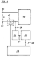
- FIG 1 illustrates a schematic diagram of a detection circuit for detecting a wrong power line connection according to a preferred embodiment of the present invention.
- the detection circuit comprises a power supply unit 10, a relay 12, detection means 14, an analogue-digital converter 16 and a microcontroller 18.
- Said detection circuit is integrated within an electric device.
- the electric device is a household appliance, like a cooking oven or a cooking hob. In the latter case the power supply unit 10 supplies the heating elements of the cooking oven or the cooking hob, respectively.
- the power supply unit 10 is directly connected to a first power input terminal 20.
- a secondary part of the relay 14 is connected to a second power input terminal 22 on a first side and to the power supply unit 10 on a second side.
- the connection between the second power input terminal 22 and the power supply unit 10 is switched by the relay 12.
- the second side of the secondary part of the relay 12 is connected to the detection means 14.
- the detection means 14 are provided to detect a residual voltage UR between the secondary part of the relay 12 and the power supply unit 10.
- the residual voltage UR depends on a supply voltage U between the first power input terminal 20 and the second power input terminal 22.
- the residual voltage UR contains information about the supply voltage U.
- the detection means 14 provide voltage value UV corresponding with the residual voltage UR.
- the detection means 14 may be realized by a voltage divider or by a network made of resistor elements. In a special case the voltage value UV may be identical with the residual voltage UR.
- the detection means 14 are connected to an input of the analogue-digital converter 16.
- the analogue-digital converter 16 receives the voltage value UV and converts it into a corresponding digital signal UD.
- An output of the analogue-digital converter 16 is connected to the microcontroller 18.
- the microcontroller 18 processes the digital signal UD. Further, the analogue-digital converter 16 may be an embedded block of the microcontroller 18.
- the microcontroller 18 is further connected to a primary part of the relay 12.
- the microcontroller 18 avoids that the relay will be closed, if the digital signal UD exceeds a predetermined value. Thus, the relay 12 cannot be closed, if the supply voltage U exceeds a predetermined value.
- the microcontroller 18 avoids that the relay 12 can be closed.
- the wrong supply voltage U may be occur, when an installer or an operator connects the first power input terminal 20 and the second power input terminal 22 with wrong power lines.
- the detection circuit may consist of components, which are already present in the electric device. For example, a direct 50 Hz synchronization circuit or some of its components may be used as a part or the complete detection circuit. Also a voltage detection circuit, which is used for power regulation, may be used as the detection circuit.
- the detection circuit may be realized within the electric device without any additional components. Thus the detection circuit is very cheap and needs no extra space on the board.
- the microcontroller 16 does not need any additional pins.
- the inventive detection circuit has low power consumption.
- the detection circuit according to the present invention is able to detect or measure the supply voltage, even if the relay 12 is open.
- the present invention can also be embedded in a computer program product, which comprises all the features enabling the implementation of the method described herein. Further, when loaded in a computer system, said computer program product is able to carry out these methods.
Landscapes
- Supply And Distribution Of Alternating Current (AREA)
- Induction Heating Cooking Devices (AREA)
Priority Applications (1)
| Application Number | Priority Date | Filing Date | Title |
|---|---|---|---|
| EP08019653.8A EP2184828B1 (fr) | 2008-11-11 | 2008-11-11 | Circuit de détection et procédé de détection d'une connexion de ligne électrique erronée |
Applications Claiming Priority (1)
| Application Number | Priority Date | Filing Date | Title |
|---|---|---|---|
| EP08019653.8A EP2184828B1 (fr) | 2008-11-11 | 2008-11-11 | Circuit de détection et procédé de détection d'une connexion de ligne électrique erronée |
Publications (2)
| Publication Number | Publication Date |
|---|---|
| EP2184828A1 true EP2184828A1 (fr) | 2010-05-12 |
| EP2184828B1 EP2184828B1 (fr) | 2019-04-24 |
Family
ID=40535599
Family Applications (1)
| Application Number | Title | Priority Date | Filing Date |
|---|---|---|---|
| EP08019653.8A Not-in-force EP2184828B1 (fr) | 2008-11-11 | 2008-11-11 | Circuit de détection et procédé de détection d'une connexion de ligne électrique erronée |
Country Status (1)
| Country | Link |
|---|---|
| EP (1) | EP2184828B1 (fr) |
Cited By (1)
| Publication number | Priority date | Publication date | Assignee | Title |
|---|---|---|---|---|
| JP2023046556A (ja) * | 2021-09-24 | 2023-04-05 | Necプラットフォームズ株式会社 | 誤接続防止装置、および誤接続防止方法 |
Citations (4)
| Publication number | Priority date | Publication date | Assignee | Title |
|---|---|---|---|---|
| US5440441A (en) * | 1984-10-24 | 1995-08-08 | Ahuja; Om | Apparatus for protecting, monitoring, and managing an AC/DC electrical line or a telecommunication line using a microprocessor |
| CN1175810A (zh) * | 1996-09-05 | 1998-03-11 | 株式会社三社电机制作所 | 过电压保护装置 |
| EP1220410A2 (fr) * | 2000-12-29 | 2002-07-03 | ABB Service Srl | Dispositif accessoire de protection contre des surtensions pour disjoncteur différentiel |
| US20070159738A1 (en) * | 2006-01-09 | 2007-07-12 | Eaton Corporation | Receptacle providing sustained excessive voltage protection |
-
2008
- 2008-11-11 EP EP08019653.8A patent/EP2184828B1/fr not_active Not-in-force
Patent Citations (4)
| Publication number | Priority date | Publication date | Assignee | Title |
|---|---|---|---|---|
| US5440441A (en) * | 1984-10-24 | 1995-08-08 | Ahuja; Om | Apparatus for protecting, monitoring, and managing an AC/DC electrical line or a telecommunication line using a microprocessor |
| CN1175810A (zh) * | 1996-09-05 | 1998-03-11 | 株式会社三社电机制作所 | 过电压保护装置 |
| EP1220410A2 (fr) * | 2000-12-29 | 2002-07-03 | ABB Service Srl | Dispositif accessoire de protection contre des surtensions pour disjoncteur différentiel |
| US20070159738A1 (en) * | 2006-01-09 | 2007-07-12 | Eaton Corporation | Receptacle providing sustained excessive voltage protection |
Cited By (1)
| Publication number | Priority date | Publication date | Assignee | Title |
|---|---|---|---|---|
| JP2023046556A (ja) * | 2021-09-24 | 2023-04-05 | Necプラットフォームズ株式会社 | 誤接続防止装置、および誤接続防止方法 |
Also Published As
| Publication number | Publication date |
|---|---|
| EP2184828B1 (fr) | 2019-04-24 |
Similar Documents
| Publication | Publication Date | Title |
|---|---|---|
| EP4032372B1 (fr) | Circuit électrique d'appareil de cuisson et appareil de cuisson | |
| US10148203B2 (en) | Motor driving apparatus including DC link voltage detection unit | |
| EP2860456A2 (fr) | Appareil domestique de cuisson modulaire doté de modules/baies de cuisson personnalisables | |
| AU2008329242B2 (en) | A method and an apparatus for controlling a cooking device, in particular an induction hob | |
| EP2184828A1 (fr) | Circuit de détection et procédé de détection d'une connexion de ligne électrique erronée | |
| KR20120001676A (ko) | 교류 전류 신호를 위한 입력 회로 및 이를 포함하는 모터 스타터 | |
| CN103797894A (zh) | 用于感应加热设备的感应发电机以及用于感应加热元件的感应发电机的操作方法 | |
| CN113966031B (zh) | 橱柜灯接口装置及照明装置接口装置 | |
| CN102549921B (zh) | 用于运行家用电器的方法和用于执行该方法的家用电器 | |
| EP4068903A1 (fr) | Circuit de chauffage | |
| KR20160077350A (ko) | 마이크로그리드의 전력계통 동기 투입을 제어하기 위한 장치 및 그 방법 | |
| JP6076309B2 (ja) | 接続関係判別システム、及び、接続関係判別方法 | |
| EP2195901B1 (fr) | Circuit de détection et procédé pour détecter une mauvaise tension d'alimentation | |
| EP2733856A1 (fr) | Appareil électronique modulaire comprenant une pluralité d'unités de circuit reliées par un bus de communication interne | |
| CN220017481U (zh) | 取暖装置的驱动电路 | |
| HK1143006A (en) | A detection circuit and a method for detecting a wrong supply voltage | |
| JP3972802B2 (ja) | 停電検出ユニットおよび電源装置 | |
| WO2016134776A1 (fr) | Appareil électroménager polyphasé ayant une sécurité accrue et procédé de commande | |
| TW200944804A (en) | Detecting circuit for three-phase input and an alternative current power supply with the same | |
| EP3806260A1 (fr) | Circuit de détection de ligne de phase et de neutre | |
| CN121208603A (zh) | 继电器粘连检测电路、方法及用电设备 | |
| GB2516748A (en) | Sample cooling device for histological samples | |
| JP2015177563A (ja) | 携帯端末、充電台、これらによる充電システム、および充電方法 | |
| KR20160121823A (ko) | 이중전원 공급장치 | |
| PL209302B1 (pl) | Układ sterujący urządzenia do gotowania, zwłaszcza zegar wyłącznikowy kuchni |
Legal Events
| Date | Code | Title | Description |
|---|---|---|---|
| PUAI | Public reference made under article 153(3) epc to a published international application that has entered the european phase |
Free format text: ORIGINAL CODE: 0009012 |
|
| AK | Designated contracting states |
Kind code of ref document: A1 Designated state(s): AT BE BG CH CY CZ DE DK EE ES FI FR GB GR HR HU IE IS IT LI LT LU LV MC MT NL NO PL PT RO SE SI SK TR |
|
| AX | Request for extension of the european patent |
Extension state: AL BA MK RS |
|
| 17P | Request for examination filed |
Effective date: 20100422 |
|
| 17Q | First examination report despatched |
Effective date: 20100528 |
|
| AKX | Designation fees paid |
Designated state(s): AT BE BG CH CY CZ DE DK EE ES FI FR GB GR HR HU IE IS IT LI LT LU LV MC MT NL NO PL PT RO SE SI SK TR |
|
| RAP1 | Party data changed (applicant data changed or rights of an application transferred) |
Owner name: ELECTROLUX HOME PRODUCTS CORPORATION N.V. |
|
| RAP1 | Party data changed (applicant data changed or rights of an application transferred) |
Owner name: ELECTROLUX HOME PRODUCTS CORPORATION N.V. |
|
| APBK | Appeal reference recorded |
Free format text: ORIGINAL CODE: EPIDOSNREFNE |
|
| APBN | Date of receipt of notice of appeal recorded |
Free format text: ORIGINAL CODE: EPIDOSNNOA2E |
|
| APBR | Date of receipt of statement of grounds of appeal recorded |
Free format text: ORIGINAL CODE: EPIDOSNNOA3E |
|
| APAF | Appeal reference modified |
Free format text: ORIGINAL CODE: EPIDOSCREFNE |
|
| APBX | Invitation to file observations in appeal sent |
Free format text: ORIGINAL CODE: EPIDOSNOBA2E |
|
| APBZ | Receipt of observations in appeal recorded |
Free format text: ORIGINAL CODE: EPIDOSNOBA4E |
|
| APBT | Appeal procedure closed |
Free format text: ORIGINAL CODE: EPIDOSNNOA9E |
|
| REG | Reference to a national code |
Ref country code: DE Ref legal event code: R079 Ref document number: 602008059822 Country of ref document: DE Free format text: PREVIOUS MAIN CLASS: H02H0003200000 Ipc: H02H0011000000 |
|
| RIC1 | Information provided on ipc code assigned before grant |
Ipc: H02H 11/00 20060101AFI20181011BHEP |
|
| GRAP | Despatch of communication of intention to grant a patent |
Free format text: ORIGINAL CODE: EPIDOSNIGR1 |
|
| STAA | Information on the status of an ep patent application or granted ep patent |
Free format text: STATUS: GRANT OF PATENT IS INTENDED |
|
| INTG | Intention to grant announced |
Effective date: 20181122 |
|
| GRAS | Grant fee paid |
Free format text: ORIGINAL CODE: EPIDOSNIGR3 |
|
| GRAA | (expected) grant |
Free format text: ORIGINAL CODE: 0009210 |
|
| STAA | Information on the status of an ep patent application or granted ep patent |
Free format text: STATUS: THE PATENT HAS BEEN GRANTED |
|
| AK | Designated contracting states |
Kind code of ref document: B1 Designated state(s): AT BE BG CH CY CZ DE DK EE ES FI FR GB GR HR HU IE IS IT LI LT LU LV MC MT NL NO PL PT RO SE SI SK TR |
|
| REG | Reference to a national code |
Ref country code: GB Ref legal event code: FG4D |
|
| REG | Reference to a national code |
Ref country code: CH Ref legal event code: EP |
|
| REG | Reference to a national code |
Ref country code: AT Ref legal event code: REF Ref document number: 1125272 Country of ref document: AT Kind code of ref document: T Effective date: 20190515 Ref country code: IE Ref legal event code: FG4D |
|
| REG | Reference to a national code |
Ref country code: DE Ref legal event code: R096 Ref document number: 602008059822 Country of ref document: DE |
|
| REG | Reference to a national code |
Ref country code: NL Ref legal event code: MP Effective date: 20190424 |
|
| REG | Reference to a national code |
Ref country code: LT Ref legal event code: MG4D |
|
| PG25 | Lapsed in a contracting state [announced via postgrant information from national office to epo] |
Ref country code: NL Free format text: LAPSE BECAUSE OF FAILURE TO SUBMIT A TRANSLATION OF THE DESCRIPTION OR TO PAY THE FEE WITHIN THE PRESCRIBED TIME-LIMIT Effective date: 20190424 |
|
| PG25 | Lapsed in a contracting state [announced via postgrant information from national office to epo] |
Ref country code: PT Free format text: LAPSE BECAUSE OF FAILURE TO SUBMIT A TRANSLATION OF THE DESCRIPTION OR TO PAY THE FEE WITHIN THE PRESCRIBED TIME-LIMIT Effective date: 20190824 Ref country code: ES Free format text: LAPSE BECAUSE OF FAILURE TO SUBMIT A TRANSLATION OF THE DESCRIPTION OR TO PAY THE FEE WITHIN THE PRESCRIBED TIME-LIMIT Effective date: 20190424 Ref country code: LT Free format text: LAPSE BECAUSE OF FAILURE TO SUBMIT A TRANSLATION OF THE DESCRIPTION OR TO PAY THE FEE WITHIN THE PRESCRIBED TIME-LIMIT Effective date: 20190424 Ref country code: NO Free format text: LAPSE BECAUSE OF FAILURE TO SUBMIT A TRANSLATION OF THE DESCRIPTION OR TO PAY THE FEE WITHIN THE PRESCRIBED TIME-LIMIT Effective date: 20190724 Ref country code: HR Free format text: LAPSE BECAUSE OF FAILURE TO SUBMIT A TRANSLATION OF THE DESCRIPTION OR TO PAY THE FEE WITHIN THE PRESCRIBED TIME-LIMIT Effective date: 20190424 Ref country code: SE Free format text: LAPSE BECAUSE OF FAILURE TO SUBMIT A TRANSLATION OF THE DESCRIPTION OR TO PAY THE FEE WITHIN THE PRESCRIBED TIME-LIMIT Effective date: 20190424 Ref country code: FI Free format text: LAPSE BECAUSE OF FAILURE TO SUBMIT A TRANSLATION OF THE DESCRIPTION OR TO PAY THE FEE WITHIN THE PRESCRIBED TIME-LIMIT Effective date: 20190424 |
|
| PG25 | Lapsed in a contracting state [announced via postgrant information from national office to epo] |
Ref country code: LV Free format text: LAPSE BECAUSE OF FAILURE TO SUBMIT A TRANSLATION OF THE DESCRIPTION OR TO PAY THE FEE WITHIN THE PRESCRIBED TIME-LIMIT Effective date: 20190424 Ref country code: PL Free format text: LAPSE BECAUSE OF FAILURE TO SUBMIT A TRANSLATION OF THE DESCRIPTION OR TO PAY THE FEE WITHIN THE PRESCRIBED TIME-LIMIT Effective date: 20190424 Ref country code: GR Free format text: LAPSE BECAUSE OF FAILURE TO SUBMIT A TRANSLATION OF THE DESCRIPTION OR TO PAY THE FEE WITHIN THE PRESCRIBED TIME-LIMIT Effective date: 20190725 Ref country code: BG Free format text: LAPSE BECAUSE OF FAILURE TO SUBMIT A TRANSLATION OF THE DESCRIPTION OR TO PAY THE FEE WITHIN THE PRESCRIBED TIME-LIMIT Effective date: 20190724 |
|
| REG | Reference to a national code |
Ref country code: AT Ref legal event code: MK05 Ref document number: 1125272 Country of ref document: AT Kind code of ref document: T Effective date: 20190424 |
|
| PG25 | Lapsed in a contracting state [announced via postgrant information from national office to epo] |
Ref country code: IS Free format text: LAPSE BECAUSE OF FAILURE TO SUBMIT A TRANSLATION OF THE DESCRIPTION OR TO PAY THE FEE WITHIN THE PRESCRIBED TIME-LIMIT Effective date: 20190824 |
|
| REG | Reference to a national code |
Ref country code: DE Ref legal event code: R097 Ref document number: 602008059822 Country of ref document: DE |
|
| PG25 | Lapsed in a contracting state [announced via postgrant information from national office to epo] |
Ref country code: CZ Free format text: LAPSE BECAUSE OF FAILURE TO SUBMIT A TRANSLATION OF THE DESCRIPTION OR TO PAY THE FEE WITHIN THE PRESCRIBED TIME-LIMIT Effective date: 20190424 Ref country code: SK Free format text: LAPSE BECAUSE OF FAILURE TO SUBMIT A TRANSLATION OF THE DESCRIPTION OR TO PAY THE FEE WITHIN THE PRESCRIBED TIME-LIMIT Effective date: 20190424 Ref country code: RO Free format text: LAPSE BECAUSE OF FAILURE TO SUBMIT A TRANSLATION OF THE DESCRIPTION OR TO PAY THE FEE WITHIN THE PRESCRIBED TIME-LIMIT Effective date: 20190424 Ref country code: DK Free format text: LAPSE BECAUSE OF FAILURE TO SUBMIT A TRANSLATION OF THE DESCRIPTION OR TO PAY THE FEE WITHIN THE PRESCRIBED TIME-LIMIT Effective date: 20190424 Ref country code: AT Free format text: LAPSE BECAUSE OF FAILURE TO SUBMIT A TRANSLATION OF THE DESCRIPTION OR TO PAY THE FEE WITHIN THE PRESCRIBED TIME-LIMIT Effective date: 20190424 Ref country code: EE Free format text: LAPSE BECAUSE OF FAILURE TO SUBMIT A TRANSLATION OF THE DESCRIPTION OR TO PAY THE FEE WITHIN THE PRESCRIBED TIME-LIMIT Effective date: 20190424 |
|
| PGFP | Annual fee paid to national office [announced via postgrant information from national office to epo] |
Ref country code: DE Payment date: 20191121 Year of fee payment: 12 |
|
| PGFP | Annual fee paid to national office [announced via postgrant information from national office to epo] |
Ref country code: IT Payment date: 20191128 Year of fee payment: 12 Ref country code: FR Payment date: 20191120 Year of fee payment: 12 |
|
| PLBE | No opposition filed within time limit |
Free format text: ORIGINAL CODE: 0009261 |
|
| STAA | Information on the status of an ep patent application or granted ep patent |
Free format text: STATUS: NO OPPOSITION FILED WITHIN TIME LIMIT |
|
| PG25 | Lapsed in a contracting state [announced via postgrant information from national office to epo] |
Ref country code: TR Free format text: LAPSE BECAUSE OF FAILURE TO SUBMIT A TRANSLATION OF THE DESCRIPTION OR TO PAY THE FEE WITHIN THE PRESCRIBED TIME-LIMIT Effective date: 20190424 |
|
| 26N | No opposition filed |
Effective date: 20200127 |
|
| PG25 | Lapsed in a contracting state [announced via postgrant information from national office to epo] |
Ref country code: SI Free format text: LAPSE BECAUSE OF FAILURE TO SUBMIT A TRANSLATION OF THE DESCRIPTION OR TO PAY THE FEE WITHIN THE PRESCRIBED TIME-LIMIT Effective date: 20190424 |
|
| REG | Reference to a national code |
Ref country code: CH Ref legal event code: PL |
|
| PG25 | Lapsed in a contracting state [announced via postgrant information from national office to epo] |
Ref country code: LU Free format text: LAPSE BECAUSE OF NON-PAYMENT OF DUE FEES Effective date: 20191111 Ref country code: MC Free format text: LAPSE BECAUSE OF FAILURE TO SUBMIT A TRANSLATION OF THE DESCRIPTION OR TO PAY THE FEE WITHIN THE PRESCRIBED TIME-LIMIT Effective date: 20190424 Ref country code: CH Free format text: LAPSE BECAUSE OF NON-PAYMENT OF DUE FEES Effective date: 20191130 Ref country code: LI Free format text: LAPSE BECAUSE OF NON-PAYMENT OF DUE FEES Effective date: 20191130 |
|
| REG | Reference to a national code |
Ref country code: BE Ref legal event code: MM Effective date: 20191130 |
|
| GBPC | Gb: european patent ceased through non-payment of renewal fee |
Effective date: 20191111 |
|
| PG25 | Lapsed in a contracting state [announced via postgrant information from national office to epo] |
Ref country code: IE Free format text: LAPSE BECAUSE OF NON-PAYMENT OF DUE FEES Effective date: 20191111 Ref country code: GB Free format text: LAPSE BECAUSE OF NON-PAYMENT OF DUE FEES Effective date: 20191111 |
|
| PG25 | Lapsed in a contracting state [announced via postgrant information from national office to epo] |
Ref country code: BE Free format text: LAPSE BECAUSE OF NON-PAYMENT OF DUE FEES Effective date: 20191130 |
|
| PG25 | Lapsed in a contracting state [announced via postgrant information from national office to epo] |
Ref country code: CY Free format text: LAPSE BECAUSE OF FAILURE TO SUBMIT A TRANSLATION OF THE DESCRIPTION OR TO PAY THE FEE WITHIN THE PRESCRIBED TIME-LIMIT Effective date: 20190424 |
|
| REG | Reference to a national code |
Ref country code: DE Ref legal event code: R119 Ref document number: 602008059822 Country of ref document: DE |
|
| PG25 | Lapsed in a contracting state [announced via postgrant information from national office to epo] |
Ref country code: MT Free format text: LAPSE BECAUSE OF FAILURE TO SUBMIT A TRANSLATION OF THE DESCRIPTION OR TO PAY THE FEE WITHIN THE PRESCRIBED TIME-LIMIT Effective date: 20190424 Ref country code: HU Free format text: LAPSE BECAUSE OF FAILURE TO SUBMIT A TRANSLATION OF THE DESCRIPTION OR TO PAY THE FEE WITHIN THE PRESCRIBED TIME-LIMIT; INVALID AB INITIO Effective date: 20081111 |
|
| PG25 | Lapsed in a contracting state [announced via postgrant information from national office to epo] |
Ref country code: FR Free format text: LAPSE BECAUSE OF NON-PAYMENT OF DUE FEES Effective date: 20201130 Ref country code: IT Free format text: LAPSE BECAUSE OF NON-PAYMENT OF DUE FEES Effective date: 20201111 |
|
| PG25 | Lapsed in a contracting state [announced via postgrant information from national office to epo] |
Ref country code: DE Free format text: LAPSE BECAUSE OF NON-PAYMENT OF DUE FEES Effective date: 20210601 |