EP2184829B1 - Automatisches Blitzschutzventil für Wasserversorgungssysteme und Verfahren zur Bereitstellung von Blitzschutz - Google Patents
Automatisches Blitzschutzventil für Wasserversorgungssysteme und Verfahren zur Bereitstellung von Blitzschutz Download PDFInfo
- Publication number
- EP2184829B1 EP2184829B1 EP20090013959 EP09013959A EP2184829B1 EP 2184829 B1 EP2184829 B1 EP 2184829B1 EP 20090013959 EP20090013959 EP 20090013959 EP 09013959 A EP09013959 A EP 09013959A EP 2184829 B1 EP2184829 B1 EP 2184829B1
- Authority
- EP
- European Patent Office
- Prior art keywords
- signal
- electromagnetic field
- atmospheric
- lightning protection
- circuit
- Prior art date
- Legal status (The legal status is an assumption and is not a legal conclusion. Google has not performed a legal analysis and makes no representation as to the accuracy of the status listed.)
- Active
Links
Images

Classifications
-
- H—ELECTRICITY
- H02—GENERATION; CONVERSION OR DISTRIBUTION OF ELECTRIC POWER
- H02H—EMERGENCY PROTECTIVE CIRCUIT ARRANGEMENTS
- H02H5/00—Emergency protective circuit arrangements for automatic disconnection directly responsive to an undesired change from normal non-electric working conditions with or without subsequent reconnection
- H02H5/005—Emergency protective circuit arrangements for automatic disconnection directly responsive to an undesired change from normal non-electric working conditions with or without subsequent reconnection responsive to ionising radiation; Nuclear-radiation circumvention circuits
-
- E—FIXED CONSTRUCTIONS
- E03—WATER SUPPLY; SEWERAGE
- E03B—INSTALLATIONS OR METHODS FOR OBTAINING, COLLECTING, OR DISTRIBUTING WATER
- E03B7/00—Water main or service pipe systems
- E03B7/07—Arrangement of devices, e.g. filters, flow controls, measuring devices, siphons or valves, in the pipe systems
- E03B7/071—Arrangement of safety devices in domestic pipe systems, e.g. devices for automatic shut-off
-
- F—MECHANICAL ENGINEERING; LIGHTING; HEATING; WEAPONS; BLASTING
- F16—ENGINEERING ELEMENTS AND UNITS; GENERAL MEASURES FOR PRODUCING AND MAINTAINING EFFECTIVE FUNCTIONING OF MACHINES OR INSTALLATIONS; THERMAL INSULATION IN GENERAL
- F16K—VALVES; TAPS; COCKS; ACTUATING-FLOATS; DEVICES FOR VENTING OR AERATING
- F16K17/00—Safety valves; Equalising valves, e.g. pressure relief valves
- F16K17/36—Safety valves; Equalising valves, e.g. pressure relief valves actuated in consequence of extraneous circumstances, e.g. shock, change of position
-
- F—MECHANICAL ENGINEERING; LIGHTING; HEATING; WEAPONS; BLASTING
- F16—ENGINEERING ELEMENTS AND UNITS; GENERAL MEASURES FOR PRODUCING AND MAINTAINING EFFECTIVE FUNCTIONING OF MACHINES OR INSTALLATIONS; THERMAL INSULATION IN GENERAL
- F16K—VALVES; TAPS; COCKS; ACTUATING-FLOATS; DEVICES FOR VENTING OR AERATING
- F16K31/00—Actuating devices; Operating means; Releasing devices
- F16K31/02—Actuating devices; Operating means; Releasing devices electric; magnetic
- F16K31/06—Actuating devices; Operating means; Releasing devices electric; magnetic using a magnet, e.g. diaphragm valves, cutting off by means of a liquid
- F16K31/0644—One-way valve
-
- F—MECHANICAL ENGINEERING; LIGHTING; HEATING; WEAPONS; BLASTING
- F17—STORING OR DISTRIBUTING GASES OR LIQUIDS
- F17D—PIPE-LINE SYSTEMS; PIPE-LINES
- F17D5/00—Protection or supervision of installations
- F17D5/08—Protection of installations or persons from the effects of high voltage induced in the pipe-line
-
- Y—GENERAL TAGGING OF NEW TECHNOLOGICAL DEVELOPMENTS; GENERAL TAGGING OF CROSS-SECTIONAL TECHNOLOGIES SPANNING OVER SEVERAL SECTIONS OF THE IPC; TECHNICAL SUBJECTS COVERED BY FORMER USPC CROSS-REFERENCE ART COLLECTIONS [XRACs] AND DIGESTS
- Y10—TECHNICAL SUBJECTS COVERED BY FORMER USPC
- Y10T—TECHNICAL SUBJECTS COVERED BY FORMER US CLASSIFICATION
- Y10T137/00—Fluid handling
- Y10T137/0318—Processes
-
- Y—GENERAL TAGGING OF NEW TECHNOLOGICAL DEVELOPMENTS; GENERAL TAGGING OF CROSS-SECTIONAL TECHNOLOGIES SPANNING OVER SEVERAL SECTIONS OF THE IPC; TECHNICAL SUBJECTS COVERED BY FORMER USPC CROSS-REFERENCE ART COLLECTIONS [XRACs] AND DIGESTS
- Y10—TECHNICAL SUBJECTS COVERED BY FORMER USPC
- Y10T—TECHNICAL SUBJECTS COVERED BY FORMER US CLASSIFICATION
- Y10T137/00—Fluid handling
- Y10T137/1842—Ambient condition change responsive
- Y10T137/1939—Atmospheric
Definitions
- This disclosure relates generally to a method of providing lightning protection and to an automatic lightning protection valve for a water supply system.
- a structure may include a lightning protection system to protect the structure from lightning bolts.
- a lightning protection system may include a rooftop network of conductors, multiple conductive paths from the roof to the ground, bonding connections to metallic objects within the structure and a grounding network.
- the structure may also include a water supply line to deliver water to the interior of the building. Water is a conductor of electricity. Therefore, if a lightning bolt hits the water supply line, the lightning bolt may bypass the other components of the lightning protection system and enter the internal water distribution system of the structure, even if the water supply line and water pipes within the structure as such are grounded. Someone inside the structure may be electrocuted. Electronics inside the structure may be damaged.
- an apparatus for lightning protection of a structure comprising a sensor device configured to sense a high current which may result from lightning, a control device configured to receive a first signal from said sensor device, and an actuator configured to receive a second signal from the control device and further configured to control a fluid flow into said structure.
- US 6,061,216 discloses a device that connects to electrical or electronic equipment that is to be protected from lightning.
- the device detects amplitude modulation radio frequency signals (electrostatic energy) emitted from an electrical storm, lightning, by a detector (2) which sends energy to signal a trigger relay (4) to activate an interval timer (6) and one of four alternate relay systems to disconnect the device and the equipment sought to be protected from a power source, antenna or other equipment.
- the device then provides power from a battery (16), thereby isolating the equipment sought to be protected from lightning damage for a predetermined interval of time.
- the device automatically reconnects and restores the device and the electrical or electronic equipment to the original power source.
- the present invention relates to an apparatus for lightning protection of a structure, comprising a sensor device configured to sense an electromagnetic field in the vicinity of the structure and to generate a corresponding first signal; a control device configured to receive said first signal from said sensor device and further configured to generate a second signal depending on the first signal, wherein, if the value of the first signal exceeds a first threshold value indicating an imminent lightning strike, the control device is configured to generate a corresponding second signal for stopping the fluid flow into said structure , and wherein, if the value of the first signal is below a second threshold value, the control device is configured to generate a corresponding second signal for allowing a fluid flow into said structure; an actuator configured to receive said second signal from said control device and further configured to stop or allow fluid flow into said structure depending on the second signal.
- the sensor device comprises at least one electromagnetic sensor.
- said actuator comprises a solenoid valve.
- the control circuit may further comprise an indicator configured to indicate that the first signal exceeds a first threshold value.
- the sensed electromagnetic field is an atmospheric electric field, such as an atmospheric electric field caused by a thunder storm.
- the present invention further relates to a method of providing lightning protection for a structure comprising the steps of measuring an atmospheric electromagnetic field in the vicinity of the structure; generating a first signal representing a measurement of the atmospheric electromagnetic field and a second signal representing a control signal depending on the first signal, wherein, if a value of the first signal exceeds a first threshold value indicating an imminent lightning strike, a corresponding second signal is generated which causes the fluid supply to the structure to be closed, and wherein, if a value of the first signal is below a second threshold value, a corresponding second signal is generated which causes the fluid supply to the structure to be open; and stopping or allowing a fluid flow into the structure depending on the second signal.
- measuring an atmospheric electromagnetic field comprises the measurement of at least one physical variable from the group comprising an electromagnetic variable, an acoustic variable, a pressure-related variable, and a temperature-related variable.
- stopping or allowing a fluid flow into the structure depending on the second signal comprises controlling a valve configured to open or close a fluid supply to the structure.
- the method may further comprise the step of grounding the fluid supply to the structure.
- the method may further comprise the step of configuring a sensor circuit to measure the atmospheric electromagnetic field and to generate the first signal representing the measurement of the atmospheric electromagnetic field.
- the present invention also relates to a system, comprising a structure; a fluid line to convey fluid to the structure; and an apparatus for lightning protection of said structure as described above.
- An exemplary embodiment provides an apparatus of lightning protection.
- a sensor circuit of the apparatus receives an electromagnetic signal of an atmospheric electromagnetic field to generate a modified signal and to communicate the modified signal to a control circuit.
- a control circuit of the apparatus of the lightening circuit causes the valve to automatically close if the modified signal is greater than a specified value.
- the valve control device is communicatively coupled with the sensor circuit.
- the apparatus also includes a solenoid valve to stop the flow of a fluid into the structure by closing a fluid line.
- the apparatus may comprise a resonance circuit of the sensor circuit to set the modified signal to a specified frequency value.
- the resonance circuit comprises a capacitor communicatively coupled to at least two electric coil units.
- the specified frequency value may comprise 300kHz.
- the sensor circuit may comprise a radio antenna to receive the radio signal of the atmospheric electromagnetic field.
- the apparatus may further comprise a power source to supply power to the control circuit and the sensor circuit; and a power supply monitor to measure an electric potential energy value of the power source.
- the power source may preferably comprise a battery to supply a direct current to a power supply monitor circuit, and the power supply monitor circuit may comprise a light emitting diode.
- the apparatus preferably comprises a flasher circuit to visually indicate when the modified signal is greater than the specified value.
- the control circuit may comprise a first transistor to amplify the modified signal, a second transistor with a switch functionality to reduce a potential difference value of the modified signal to less than an other potential difference value of the modified signal at a capacitor communicatively coupled to the second transistor, and wherein the second transistor is communicatively coupled with the first transistor, a third transistor with a switch functionality, and wherein the third transistor is communicatively coupled with the second transistor, a fourth transistor and a light emitting device, and wherein the fourth transistor and the light emitting device are communicatively coupled with the third transistor, a rectifier circuit comprising at least one diode and at least one capacitor to transform an alternating current of the modified signal to a direct current, a variable resistance circuit comprising at least one other diode communicatively coupled with a voltage source, and wherein the variable resistance current diode impedes a positive voltage from being communicated to the fifth transistor if a positive voltage value is less than a voltage of the voltage source, and wherein the variable resistance circuit communicates
- the apparatus may further comprise a ground coupled to the solenoid valve.
- a method of lightning protection comprises measuring an atmospheric electromagnetic field; generating a signal representing a measurement of the atmospheric electromagnetic field; and automatically shutting off a water supply line to a structure if the measurement of the atmospheric electromagnetic field is greater than a specified value.
- the method may further comprise causing a solenoid valve to obstruct an aperture of the water supply line if the measurement of the atmospheric electromagnetic field is greater than the specified value.
- the water supply line to the structure may flow through the aperture.
- the method preferably comprises grounding the water supply line.
- the valve may comprise a non-conducting material to insulate an internal water supply line of the structure from the electric charge of the lightning bolt in the external water supply line.
- the specified value the measurement of the atmospheric electromagnetic field could, for instance, indicate a substantial probability of an atmospheric discharge of electricity within a specified range from the structure.
- the method may further comprise configuring a sensor circuit comprising hardware devices to measure the atmospheric electromagnetic field and to generate the signal representing the measurement of the atmospheric electromagnetic field.
- the method preferably comprises causing the aperture to open if the measurement of the atmospheric electromagnetic field is less than the specified value.
- An exemplary embodiment provides a method of lightning protection.
- An atmospheric electromagnetic field is measured.
- a signal representing a measurement of the atmospheric electromagnetic field is generated.
- a water supply line to a structure is automatically shut off if the measurement of the atmospheric electromagnetic field is greater than a specified value.
- An exemplary embodiment provides a system of lightning protection.
- the system includes a structure and a waterline to convey water to the structure.
- the system also includes a solenoid valve to control the waterline at the boundary of the structure.
- An antenna of the lightning protection system receives an atmospheric electromagnetic signal.
- a signal processing circuit of the system processes the atmospheric electromagnetic signal and communicates a processed signal to solenoid valve.
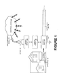
- Figure 1 is a diagrammatic view illustrating a lightening protection system for a structure, according to one embodiment. Particularly, Figure 1 illustrates a sensor in the form of an electromagnetic antenna 100, a sensor circuit 102, a control circuit 104, a water supply line 106, an electrical storm 108, a structure 110, an actuator in the form of a solenoid valve 112, an electromagnetic signal 114, and a ground 116 according to one embodiment.
- the structure 110 is coupled to the water supply line 106.
- the solenoid valve 112 is coupled to the water supply line 106 and the control circuit 104.
- the solenoid valve 112 may be grounded.
- the control circuit 104 is coupled to the sensor circuit 102.
- the sensor circuit 102 is connected to the antenna 100.
- the antenna 100 may receive the electromagnetic signal 114 from the electrical storm 108.
- the water supply line 106 may be an external source of water to the structure.
- the water supply line 106 may be vulnerable to a lightning strike.
- the water supply line 106 may include liquid and/or gaseous chemicals.
- the sensor circuit 102 includes the antenna 100.
- the antenna includes a component designed to send and receive radio waves.
- the antenna includes an aerial antenna.
- the antenna 100 includes an array of antennas communicatively coupled with each other.
- the antenna 100 may include a transducer designed to transmit and/or receive electromagnetic waves.
- the sensor circuit 102 converts electromagnetic waves received by the antenna into a modified signal (first signal) and/or vice versa.
- the sensor circuit 102 communicates the modified signal to the control circuit 104.
- the control circuit 104 includes an interconnection of electrical elements including resistors, inductors, capacitors, transmission lines, voltage sources, current sources, and switches.
- the control circuit 104 shares a solenoid of the solenoid valve 112.
- the control circuit 104 may further communicate the modified signal as a second signal to the solenoid.
- the control circuit 104 transforms the modified signal into a second signal.
- the control circuit 104 may filter the modified signal.
- the control circuit 104 may also strengthen the modified signal.
- the solenoid valve 112 includes an electromechanical valve for use with a liquid and/or gas.
- the solenoid valve 112 is controlled by running and/or stopping an electric current through a solenoid, in order to change the state of the valve.
- the solenoid valve 112 converts electrical energy into mechanical energy which, in turn, opens or closes the valve mechanically.
- the sensor circuit 102 receives an electromagnetic signal 114 of a specified value indicating an imminent lightning strike from the electrical storm 108.
- the sensor circuit 102 generates the modified signal (first signal) from the electromagnetic signal 114.
- the sensor circuit 102 communicates the modified signal to the control circuit 104.
- the control circuit 104 further processes the modified signal (i.e. first signal) into a value (i.e. second signal) capable of activating the solenoid valve 112.
- the solenoid valve 112 then terminates the flow of water through the water supply line 106. A current of a lightning strike to the water supply line 106 is then conveyed to the ground 116.
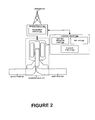
- Figure 2 is a systematic view illustrating correlation of an actuator, such as a solenoid valve with control circuit and sensor circuit, according to one embodiment.
- Figure 2 illustrates an aerial antenna 200, a sensor circuit 202, a control circuit 204, a battery 214, a solenoid valve 212, a flasher circuit 218, a battery indicator light 220, a resonance circuit 222, an outlet port 224 and an inlet port 222, according to one embodiment.
- the solenoid valve 212 includes the inlet port 222 and the outlet port 224.
- the solenoid valve 212 is coupled with the control circuit 204 and the sensor circuit 202.
- the control circuit 204 includes the battery 214, the battery indicator light 220, and the flasher circuit 218.
- the sensor circuit 202 includes a resonance circuit 222.
- the control circuit 204 communicates to the sensor circuit 202.
- the sensor circuit 202 is connected to the antenna 100.
- the battery 214 includes a device that converts chemical energy to electrical energy.
- the battery 214 supplies the electrical energy to the control circuit 204.
- the battery indicator light 220 indicates that the battery 214 has fallen below a specified amount of chemical energy.
- the resonance circuit 222 of the sensor circuit adjusts the modified signal, i.e. first singal, to a specified frequency value, i.e. second signal.
- the specified value may be a frequency value of 300kHz.
- the resonance circuit may include a capacitor communicatively coupled to at least two electric coil units.
- the inlet port 222 transports a dielectric fluid and/or gas (e.g. water) from an external supply line to the solenoid valve 212.
- the outlet port 224 of the solenoid valve transports the dielectric fluid and/or gas to the structure 100.
- Figure 3 is a schematic view illustrating the arrangement of circuits in the lightning protection system, according to one embodiment. Particularly, Figure 3 illustrates an antenna 300, a sensor circuit 302, a control circuit 304, a solenoid valve 312, a battery 314, a light indicator 318, and an alarm circuit 316, according to one embodiment.
- the antenna 300 is connected to the sensor circuit 302.
- the sensor circuit 302 is coupled to the light indicator 318.
- the control circuit 304 communicates with the light indicator 318 and the solenoid valve 312.
- the control circuit 304 communicates with the alarm circuit 316.
- the alarm circuit 316 is coupled to the battery 314.
- the antenna 310 receives an atmospheric electromagnetic signal.
- the sensor circuit 302 and the control circuit are included in a signal processing circuit.
- the signal processing circuit processes the atmospheric electromagnetic signal and communicates a processed signal to a solenoid of the solenoid valve 312.
- the alarm circuit 316 may indicate that the sensor circuit 302 has received an electromagnetic signal greater than the specified value.
- the alarm circuit 316 may indicate a specified probability that a lightning bolt may be produced by an electric storm 108.
- the solenoid valve 312 controls the waterline at the boundary of the structure.
- the solenoid valve 312 may block the flow of water in the waterline depending on the received processed signal.
- the solenoid valve 312 may thus creates an opening in the path of the water with a functional infinite resistance to a current produced by a lighting strike on the waterline.
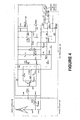
- Figure 4 is a schematic view illustrating the arrangement of a sensor circuit, a control circuit, and a solenoid valve, according to one embodiment. Particularly, Figure 4 illustrates an antenna 400, sensor circuit 402, a control circuit 404, and a solenoid of solenoid valve 412, according to one embodiment.
- the antenna is connected to the sensor circuit 402.
- the sensor circuit 402 is coupled to the control circuit 404.
- the control circuit is coupled to the solenoid of solenoid valve 412.
- the antenna 400 includes a transducer designed to transmit and/or receive electromagnetic waves.
- the control circuit 404 includes a power source to supply power to the control circuit and the sensor circuit.
- the control circuit 404 includes a power supply monitor to measure an electric potential energy value of the power source.
- the power source includes a battery.
- the power supply monitor includes a light emitting diode.
- the control circuit 404 includes a flasher circuit with another light emitting diode to indicate if the sensor circuit 402 has detected an electromagnetic wave above a specified threshold.
- the control circuit 404 includes a first transistor to amplify the modified signal.
- the control circuit 404 includes a second transistor with a switch functionality to reduce a potential difference value of the modified signal to less than another potential difference value of the modified signal at a capacitor communicatively coupled to the second transistor.
- the second transistor is communicatively coupled with the first transistor.
- the control circuit 404 includes a third transistor with a switch functionality.
- the third transistor may be communicatively coupled with the second transistor.
- the control circuit 404 includes a fourth transistor and a light emitting device, and wherein the fourth transistor and the light emitting device are communicatively coupled with the third transistor.
- the control circuit 404 includes a rectifier circuit, comprising at least one diode and at least one capacitor to transform an alternating current of the modified signal to a direct current.
- the control circuit 404 includes a variable resistance circuit comprising at least one other diode communicatively coupled with a voltage source, and wherein the variable resistance current diode impedes a positive voltage from being communicated to the fifth transistor if a positive voltage value is less than a voltage of the voltage source.
- the variable resistance circuit communicates a positive voltage to the fifth transistor.
- the control circuit 404 includes an operational amplifier to combine the modified signal and the voltage of the voltage source.
- the operational amplifier is communicatively coupled with the fifth transistor and a solenoid of the solenoid valve.
- the control circuit 404 includes a sixth transistor to function as a switch and to render the modified signal to the solenoid if the value of the modified signal is at least one of equal to and greater than the voltage of the voltage source.
- the control circuit 404 may also include a second flasher circuit composed of two transistors (in case the potential difference is less than 4.7 V).
- the modified signal may be received by an LED to indicate that the energy coming from the battery is about to come to an end.
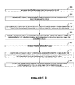
- FIG. 5 is a process flow that illustrates a method of providing lighting protection for a water supply system, according to another embodiment.
- an atmospheric electromagnetic field is measured.
- a signal i.e. a first signal, representing a measurement of the atmospheric electromagnetic field is generated.
- a water supply line 106 to a structure 110 is automatically shut off if the measurement of the atmospheric electromagnetic field represented by the first signal is greater than a specified value.
- the specified value may be 300 kHz.
- a solenoid valve 112 is caused to obstruct an aperture of the water supply line 106 if the measurement of the atmospheric electromagnetic field is greater than the specified value thereby the fluid supply to said structure.
- the water supply line to the structure 110 may flow through the aperture.
- the water supply line 106 is grounded.
- the valve may include a non conducting material to insulate an internal water supply line of the structure 110 from the electric charge of the lightning bolt in the external water supply line.
- the specified value of the measurement of the atmospheric electromagnetic field may indicate a substantial probability of an atmospheric discharge of electricity within a specified range from the structure 110.
- a sensor circuit 202 including hardware devices is configured to measure the atmospheric electromagnetic field and to generate the signal representing the measurement of the atmospheric electromagnetic field.
- the aperture is caused to open if the measurement of the atmospheric electromagnetic field is less than the specified value.
- a valve control device may open the solenoid valve 112 if the processed signal indicates the atmospheric electromagnetic signal is less than the specified value.
- the various devices, modules, analyzers, generators, etc. described herein may be enabled and operated using hardware circuitry, firmware, software or any combination of hardware, firmware, or software embodied in a machine readable medium.
- the various electrical structures and methods may be embodied using transistors, logic gates, application specific integrated (ASIC) circuitry or Digital Signal Processor (DSP) circuitry.
Landscapes
- Engineering & Computer Science (AREA)
- General Engineering & Computer Science (AREA)
- Mechanical Engineering (AREA)
- Health & Medical Sciences (AREA)
- Life Sciences & Earth Sciences (AREA)
- Hydrology & Water Resources (AREA)
- Public Health (AREA)
- Water Supply & Treatment (AREA)
- Physics & Mathematics (AREA)
- High Energy & Nuclear Physics (AREA)
- Emergency Protection Circuit Devices (AREA)
- Elimination Of Static Electricity (AREA)
Claims (11)
- Vorrichtung zum Schutz eines Gebäudes vor Blitzen, umfassend:eine Sensoreinrichtung (102; 202; 302; 402) zum Messen eines elektromagnetischen Felds (108) in der Nähe des Gebäudes (110) und zum Erzeugen eines korrespondierenden ersten Signals;eine Steuereinrichtung (104, 204; 304; 404) zum Empfangen des ersten Signals von der Sensoreinrichtung (102; 202; 302; 402) und ferner zum Erzeugen eines von dem ersten Signal abhängigen zweiten Signals, wobei, wenn der Wert des ersten Signals einen ersten Schwellenwert überschreitet, der auf einen bevorstehenden Blitzeinschlag hinweist, die Steuereinrichtung (104, 204; 304; 404) konfiguriert ist, um ein korrespondierendes zweites Signal zum Stoppen des Strömens von Fluid in das Gebäude (110) zu erzeugen, und wobei, wenn der Wert des ersten Signals unterhalb eines zweiten Schwellenwerts liegt, die Steuereinrichtung (104, 204; 304; 404) konfiguriert ist, um ein korrespondierendes zweites Signal zum Zulassen des Strömens eines Fluids in das Gebäude (110) zu erzeugen;einen Aktuator (112; 212; 312; 412), der zum Empfangen des zweiten Signals von der Steuereinrichtung (104, 204; 304; 404) konfiguriert ist und ferner konfiguriert ist, um das Strömen von Fluid in das Gebäude (110) in Abhängigkeit von dem zweiten Signal zu stoppen oder zuzulassen.
- Vorrichtung nach Anspruch 1, wobei die Sensoreinrichtung (102; 202; 302; 402) mindestens einen elektromagnetischen Sensor (100; 200; 300, 400) umfasst.
- Vorrichtung nach einem der vorangehenden Ansprüche, wobei der Aktuator (112; 212; 312; 412) ein Magnetventil umfasst.
- Vorrichtung nach einem der vorangehenden Ansprüche, wobei die Steuereinrichtung (204; 304; 404) ferner eine Anzeigeeinrichtung (218; 318) umfasst, die konfiguriert ist, um anzuzeigen, dass das erste Signal einen ersten Schwellenwert überschreitet.
- Vorrichtung nach einem der vorangehenden Ansprüche, wobei das gemessene elektromagnetische Feld ein atmosphärisches elektrisches Feld, wie zum Beispiel ein durch ein Gewitter verursachtes atmosphärisches elektrisches Feld, ist.
- Verfahren zur Bereitstellung von Blitzschutz für ein Gebäude, umfassend die Schritte:Messen (502) eines atmosphärischen elektromagnetischen Felds in der Nähe des Gebäudes;Erzeugen (504) eines ersten Signals, das einen Messwert des atmosphärischen elektromagnetischen Felds repräsentiert, und eines zweiten Signals, das ein von dem ersten Signal abhängiges Steuersignal repräsentiert, wobei, wenn ein Wert des ersten Signals einen ersten Schwellenwert überschreitet, der auf einen bevorstehenden Blitzeinschlag hinweist, ein korrespondierendes zweites Signal erzeugt wird, das bewirkt, dass die Fluidzufuhr zum Gebäude abgesperrt wird, und wobei, wenn ein Wert des ersten Signals unterhalb eines zweiten Schwellenwerts liegt, ein korrespondierendes zweites Signal erzeugt wird, das bewirkt, dass die Fluidzufuhr zum Gebäude geöffnet wird; undStoppen oder Zulassen einer Strömung von Fluid in das Gebäude in Abhängigkeit von dem zweiten Signal.
- Verfahren nach Anspruch 6, wobei das Messen (502) eines atmosphärischen elektromagnetischen Felds das Messen von mindestens einer elektromagnetischen Variablen umfasst.
- Verfahren nach einem der Ansprüche 6 oder 7, wobei das Stoppen oder Zulassen einer Strömung von Fluid in das Gebäude in Abhängigkeit von dem zweiten Signal ein Steuern eines Ventils umfasst, das konfiguriert ist, um eine Fluidzufuhr zum Gebäude zu öffnen oder abzusperren.
- Verfahren nach Anspruch 8, ferner umfassend den Schritt des Erdens (510) der Fluidzufuhr zum Gebäude.
- Verfahren nach einem der Ansprüche 6 bis 9, ferner umfassend den Schritt des Konfigurierens (512) einer Sensorschaltung zum Messen des atmosphärischen elektromagnetischen Felds und zum Erzeugen des ersten Signals, das den Messwert für das atmosphärische elektromagnetische Feld repräsentiert.
- System, umfassend:ein Gebäude (110);eine Fluidleitung (106) zum Fördern von Fluid zum Gebäude (110); undeine Vorrichtung zum Schutz eines Gebäudes (110) vor Blitzen gemäß einem der Ansprüche 1 bis 5.
Applications Claiming Priority (2)
| Application Number | Priority Date | Filing Date | Title |
|---|---|---|---|
| SA29071108 | 2008-11-08 | ||
| US12/425,470 US8203820B2 (en) | 2008-11-08 | 2009-04-17 | Automatic lightning safety valve for water supply system |
Publications (3)
| Publication Number | Publication Date |
|---|---|
| EP2184829A2 EP2184829A2 (de) | 2010-05-12 |
| EP2184829A3 EP2184829A3 (de) | 2012-04-11 |
| EP2184829B1 true EP2184829B1 (de) | 2015-01-07 |
Family
ID=41667347
Family Applications (1)
| Application Number | Title | Priority Date | Filing Date |
|---|---|---|---|
| EP20090013959 Active EP2184829B1 (de) | 2008-11-08 | 2009-11-06 | Automatisches Blitzschutzventil für Wasserversorgungssysteme und Verfahren zur Bereitstellung von Blitzschutz |
Country Status (2)
| Country | Link |
|---|---|
| US (1) | US8203820B2 (de) |
| EP (1) | EP2184829B1 (de) |
Families Citing this family (7)
| Publication number | Priority date | Publication date | Assignee | Title |
|---|---|---|---|---|
| US9097389B2 (en) * | 2009-08-03 | 2015-08-04 | Goodson Holdings, Llc | Apparatus and method for detection and cessation of unintended gas flow |
| GB2493521A (en) * | 2011-08-08 | 2013-02-13 | Leonard Maxwell | System for shutting off utility valves |
| US8720470B2 (en) * | 2012-02-12 | 2014-05-13 | Abdollah Hosseini | Intelligent emergency shut down system and a method for emergency closing and regulation of fluid stream in fluid storage and dispensing systems during earthquake |
| US8944088B2 (en) * | 2012-06-21 | 2015-02-03 | Richard T. Gilmer | Safety valve |
| US10948929B1 (en) * | 2019-02-26 | 2021-03-16 | Utility Isolation Systems LLC | Building utility floodwater isolation system |
| AU2020299392B2 (en) * | 2019-07-03 | 2024-05-30 | Earth Networks, Inc. | Antenna for use with lightning detection sensor |
| CN118393581B (zh) * | 2024-05-07 | 2024-10-11 | 中国地质大学(武汉) | 一种电磁法仪器通用化通道装置及控制方法 |
Citations (1)
| Publication number | Priority date | Publication date | Assignee | Title |
|---|---|---|---|---|
| US6061216A (en) * | 1996-08-08 | 2000-05-09 | Fuqua, Iii; Charles H. | Lightning breaker |
Family Cites Families (3)
| Publication number | Priority date | Publication date | Assignee | Title |
|---|---|---|---|---|
| US5083042A (en) * | 1990-07-06 | 1992-01-21 | Merchant Roger R | Unplugging apparatus |
| US5453899A (en) * | 1993-04-05 | 1995-09-26 | Page; J. Dennis | Lightning protection device |
| US20070095400A1 (en) * | 2005-11-03 | 2007-05-03 | Parker-Hannifin Corporation | Shut-off valve system |
-
2009
- 2009-04-17 US US12/425,470 patent/US8203820B2/en not_active Expired - Fee Related
- 2009-11-06 EP EP20090013959 patent/EP2184829B1/de active Active
Patent Citations (1)
| Publication number | Priority date | Publication date | Assignee | Title |
|---|---|---|---|---|
| US6061216A (en) * | 1996-08-08 | 2000-05-09 | Fuqua, Iii; Charles H. | Lightning breaker |
Also Published As
| Publication number | Publication date |
|---|---|
| EP2184829A2 (de) | 2010-05-12 |
| US8203820B2 (en) | 2012-06-19 |
| EP2184829A3 (de) | 2012-04-11 |
| US20100263729A1 (en) | 2010-10-21 |
Similar Documents
| Publication | Publication Date | Title |
|---|---|---|
| EP2184829A2 (de) | Automatisches Blitzschutzventil für Wasserversorgungssysteme und Verfahren zur Bereitstellung von Blitzschutz | |
| US10754365B2 (en) | System and method for arc detection and intervention in solar energy systems | |
| CA2907434C (en) | Device for protecting electrical networks | |
| WO2009112165A3 (de) | Verfahren und eine vorrichtung zur überwachung von hochvoltverbindungen eines hybridfahrzeugs | |
| US20040156153A1 (en) | Arc fault detection system | |
| KR101550689B1 (ko) | 잡음제거 기능을 구비한 ae센서 기반 수배전반의 아크 및 코로나 검출 시스템 | |
| AU2020361439B2 (en) | System and method for detecting and isolating an electromagnetic pulse for protection of a monitored infrastructure | |
| CA2731453A1 (en) | Programmable lightning detector | |
| CN106093721A (zh) | 发电系统中的电弧检测和预防 | |
| KR102227603B1 (ko) | 접지분리를 이용한 통합형 누액감지 경보시스템 | |
| EP4073896B1 (de) | Verfahren und system zur detektion eines seriellen lichtbogens in einer leistungsschaltung | |
| US6788075B2 (en) | Anode monitoring | |
| US8467161B2 (en) | Device for protecting a DC voltage converter | |
| US20130107406A1 (en) | Process control field device with circuitry protection | |
| US10660195B2 (en) | Printed circuit board and electronic component package including same | |
| US11539200B2 (en) | Monitor device, ground fault protection circuit and techniques | |
| KR102596766B1 (ko) | 태양광 시스템 설치용 직류 아크 3중화 검출장치 | |
| WO2021242398A3 (en) | Devices, systems and methods for reducing conducted and radiated emissions and susceptibility | |
| US10310001B2 (en) | Short-circuit sensor | |
| JP2007286875A (ja) | 振動検出装置とそれを備えた侵入検知システム | |
| CN106602500A (zh) | 一种新型保护接地带电报警及保护电路 | |
| CN103325614A (zh) | 用于检测真空断路器真空度的方法和装置 | |
| JP7616606B2 (ja) | 雷警報装置 | |
| RU2204168C2 (ru) | Устройство дистанционного контроля работоспособности установок катодной защиты магистральных трубопроводов | |
| CN203377161U (zh) | 用于检测真空断路器真空度的装置 |
Legal Events
| Date | Code | Title | Description |
|---|---|---|---|
| PUAI | Public reference made under article 153(3) epc to a published international application that has entered the european phase |
Free format text: ORIGINAL CODE: 0009012 |
|
| AK | Designated contracting states |
Kind code of ref document: A2 Designated state(s): AT BE BG CH CY CZ DE DK EE ES FI FR GB GR HR HU IE IS IT LI LT LU LV MC MK MT NL NO PL PT RO SE SI SK SM TR |
|
| AX | Request for extension of the european patent |
Extension state: AL BA RS |
|
| PUAL | Search report despatched |
Free format text: ORIGINAL CODE: 0009013 |
|
| AK | Designated contracting states |
Kind code of ref document: A3 Designated state(s): AT BE BG CH CY CZ DE DK EE ES FI FR GB GR HR HU IE IS IT LI LT LU LV MC MK MT NL NO PL PT RO SE SI SK SM TR |
|
| AX | Request for extension of the european patent |
Extension state: AL BA RS |
|
| RIC1 | Information provided on ipc code assigned before grant |
Ipc: F16K 17/36 20060101ALI20120305BHEP Ipc: E03B 7/07 20060101ALI20120305BHEP Ipc: F16K 31/06 20060101ALI20120305BHEP Ipc: F17D 5/08 20060101ALI20120305BHEP Ipc: H02H 5/00 20060101AFI20120305BHEP |
|
| 17P | Request for examination filed |
Effective date: 20121008 |
|
| 17Q | First examination report despatched |
Effective date: 20130225 |
|
| GRAP | Despatch of communication of intention to grant a patent |
Free format text: ORIGINAL CODE: EPIDOSNIGR1 |
|
| INTG | Intention to grant announced |
Effective date: 20141023 |
|
| RIN1 | Information on inventor provided before grant (corrected) |
Inventor name: KHONKAR, HUSSAMELDIN I. |
|
| GRAS | Grant fee paid |
Free format text: ORIGINAL CODE: EPIDOSNIGR3 |
|
| GRAA | (expected) grant |
Free format text: ORIGINAL CODE: 0009210 |
|
| AK | Designated contracting states |
Kind code of ref document: B1 Designated state(s): AT BE BG CH CY CZ DE DK EE ES FI FR GB GR HR HU IE IS IT LI LT LU LV MC MK MT NL NO PL PT RO SE SI SK SM TR |
|
| REG | Reference to a national code |
Ref country code: GB Ref legal event code: FG4D |
|
| REG | Reference to a national code |
Ref country code: CH Ref legal event code: EP |
|
| REG | Reference to a national code |
Ref country code: IE Ref legal event code: FG4D |
|
| REG | Reference to a national code |
Ref country code: AT Ref legal event code: REF Ref document number: 706316 Country of ref document: AT Kind code of ref document: T Effective date: 20150215 |
|
| REG | Reference to a national code |
Ref country code: DE Ref legal event code: R096 Ref document number: 602009028782 Country of ref document: DE Effective date: 20150226 |
|
| REG | Reference to a national code |
Ref country code: NL Ref legal event code: VDEP Effective date: 20150107 |
|
| REG | Reference to a national code |
Ref country code: AT Ref legal event code: MK05 Ref document number: 706316 Country of ref document: AT Kind code of ref document: T Effective date: 20150107 |
|
| REG | Reference to a national code |
Ref country code: LT Ref legal event code: MG4D |
|
| PG25 | Lapsed in a contracting state [announced via postgrant information from national office to epo] |
Ref country code: BG Free format text: LAPSE BECAUSE OF FAILURE TO SUBMIT A TRANSLATION OF THE DESCRIPTION OR TO PAY THE FEE WITHIN THE PRESCRIBED TIME-LIMIT Effective date: 20150407 Ref country code: LT Free format text: LAPSE BECAUSE OF FAILURE TO SUBMIT A TRANSLATION OF THE DESCRIPTION OR TO PAY THE FEE WITHIN THE PRESCRIBED TIME-LIMIT Effective date: 20150107 Ref country code: FI Free format text: LAPSE BECAUSE OF FAILURE TO SUBMIT A TRANSLATION OF THE DESCRIPTION OR TO PAY THE FEE WITHIN THE PRESCRIBED TIME-LIMIT Effective date: 20150107 Ref country code: NO Free format text: LAPSE BECAUSE OF FAILURE TO SUBMIT A TRANSLATION OF THE DESCRIPTION OR TO PAY THE FEE WITHIN THE PRESCRIBED TIME-LIMIT Effective date: 20150407 Ref country code: HR Free format text: LAPSE BECAUSE OF FAILURE TO SUBMIT A TRANSLATION OF THE DESCRIPTION OR TO PAY THE FEE WITHIN THE PRESCRIBED TIME-LIMIT Effective date: 20150107 Ref country code: ES Free format text: LAPSE BECAUSE OF FAILURE TO SUBMIT A TRANSLATION OF THE DESCRIPTION OR TO PAY THE FEE WITHIN THE PRESCRIBED TIME-LIMIT Effective date: 20150107 Ref country code: SE Free format text: LAPSE BECAUSE OF FAILURE TO SUBMIT A TRANSLATION OF THE DESCRIPTION OR TO PAY THE FEE WITHIN THE PRESCRIBED TIME-LIMIT Effective date: 20150107 |
|
| PG25 | Lapsed in a contracting state [announced via postgrant information from national office to epo] |
Ref country code: IS Free format text: LAPSE BECAUSE OF FAILURE TO SUBMIT A TRANSLATION OF THE DESCRIPTION OR TO PAY THE FEE WITHIN THE PRESCRIBED TIME-LIMIT Effective date: 20150507 Ref country code: PL Free format text: LAPSE BECAUSE OF FAILURE TO SUBMIT A TRANSLATION OF THE DESCRIPTION OR TO PAY THE FEE WITHIN THE PRESCRIBED TIME-LIMIT Effective date: 20150107 Ref country code: LV Free format text: LAPSE BECAUSE OF FAILURE TO SUBMIT A TRANSLATION OF THE DESCRIPTION OR TO PAY THE FEE WITHIN THE PRESCRIBED TIME-LIMIT Effective date: 20150107 Ref country code: AT Free format text: LAPSE BECAUSE OF FAILURE TO SUBMIT A TRANSLATION OF THE DESCRIPTION OR TO PAY THE FEE WITHIN THE PRESCRIBED TIME-LIMIT Effective date: 20150107 Ref country code: NL Free format text: LAPSE BECAUSE OF FAILURE TO SUBMIT A TRANSLATION OF THE DESCRIPTION OR TO PAY THE FEE WITHIN THE PRESCRIBED TIME-LIMIT Effective date: 20150107 Ref country code: GR Free format text: LAPSE BECAUSE OF FAILURE TO SUBMIT A TRANSLATION OF THE DESCRIPTION OR TO PAY THE FEE WITHIN THE PRESCRIBED TIME-LIMIT Effective date: 20150408 |
|
| REG | Reference to a national code |
Ref country code: DE Ref legal event code: R097 Ref document number: 602009028782 Country of ref document: DE |
|
| PG25 | Lapsed in a contracting state [announced via postgrant information from national office to epo] |
Ref country code: DK Free format text: LAPSE BECAUSE OF FAILURE TO SUBMIT A TRANSLATION OF THE DESCRIPTION OR TO PAY THE FEE WITHIN THE PRESCRIBED TIME-LIMIT Effective date: 20150107 Ref country code: EE Free format text: LAPSE BECAUSE OF FAILURE TO SUBMIT A TRANSLATION OF THE DESCRIPTION OR TO PAY THE FEE WITHIN THE PRESCRIBED TIME-LIMIT Effective date: 20150107 Ref country code: CZ Free format text: LAPSE BECAUSE OF FAILURE TO SUBMIT A TRANSLATION OF THE DESCRIPTION OR TO PAY THE FEE WITHIN THE PRESCRIBED TIME-LIMIT Effective date: 20150107 Ref country code: SK Free format text: LAPSE BECAUSE OF FAILURE TO SUBMIT A TRANSLATION OF THE DESCRIPTION OR TO PAY THE FEE WITHIN THE PRESCRIBED TIME-LIMIT Effective date: 20150107 Ref country code: RO Free format text: LAPSE BECAUSE OF FAILURE TO SUBMIT A TRANSLATION OF THE DESCRIPTION OR TO PAY THE FEE WITHIN THE PRESCRIBED TIME-LIMIT Effective date: 20150107 |
|
| PLBE | No opposition filed within time limit |
Free format text: ORIGINAL CODE: 0009261 |
|
| STAA | Information on the status of an ep patent application or granted ep patent |
Free format text: STATUS: NO OPPOSITION FILED WITHIN TIME LIMIT |
|
| 26N | No opposition filed |
Effective date: 20151008 |
|
| REG | Reference to a national code |
Ref country code: FR Ref legal event code: PLFP Year of fee payment: 7 |
|
| PG25 | Lapsed in a contracting state [announced via postgrant information from national office to epo] |
Ref country code: IT Free format text: LAPSE BECAUSE OF FAILURE TO SUBMIT A TRANSLATION OF THE DESCRIPTION OR TO PAY THE FEE WITHIN THE PRESCRIBED TIME-LIMIT Effective date: 20150107 |
|
| PG25 | Lapsed in a contracting state [announced via postgrant information from national office to epo] |
Ref country code: SI Free format text: LAPSE BECAUSE OF FAILURE TO SUBMIT A TRANSLATION OF THE DESCRIPTION OR TO PAY THE FEE WITHIN THE PRESCRIBED TIME-LIMIT Effective date: 20150107 |
|
| PG25 | Lapsed in a contracting state [announced via postgrant information from national office to epo] |
Ref country code: BE Free format text: LAPSE BECAUSE OF FAILURE TO SUBMIT A TRANSLATION OF THE DESCRIPTION OR TO PAY THE FEE WITHIN THE PRESCRIBED TIME-LIMIT Effective date: 20150107 |
|
| PG25 | Lapsed in a contracting state [announced via postgrant information from national office to epo] |
Ref country code: LU Free format text: LAPSE BECAUSE OF FAILURE TO SUBMIT A TRANSLATION OF THE DESCRIPTION OR TO PAY THE FEE WITHIN THE PRESCRIBED TIME-LIMIT Effective date: 20151106 Ref country code: MC Free format text: LAPSE BECAUSE OF FAILURE TO SUBMIT A TRANSLATION OF THE DESCRIPTION OR TO PAY THE FEE WITHIN THE PRESCRIBED TIME-LIMIT Effective date: 20150107 |
|
| REG | Reference to a national code |
Ref country code: CH Ref legal event code: PL |
|
| GBPC | Gb: european patent ceased through non-payment of renewal fee |
Effective date: 20151106 |
|
| PG25 | Lapsed in a contracting state [announced via postgrant information from national office to epo] |
Ref country code: LI Free format text: LAPSE BECAUSE OF NON-PAYMENT OF DUE FEES Effective date: 20151130 Ref country code: CH Free format text: LAPSE BECAUSE OF NON-PAYMENT OF DUE FEES Effective date: 20151130 |
|
| REG | Reference to a national code |
Ref country code: IE Ref legal event code: MM4A |
|
| REG | Reference to a national code |
Ref country code: FR Ref legal event code: PLFP Year of fee payment: 8 |
|
| PG25 | Lapsed in a contracting state [announced via postgrant information from national office to epo] |
Ref country code: GB Free format text: LAPSE BECAUSE OF NON-PAYMENT OF DUE FEES Effective date: 20151106 Ref country code: IE Free format text: LAPSE BECAUSE OF NON-PAYMENT OF DUE FEES Effective date: 20151106 |
|
| PGFP | Annual fee paid to national office [announced via postgrant information from national office to epo] |
Ref country code: FR Payment date: 20161014 Year of fee payment: 8 |
|
| PG25 | Lapsed in a contracting state [announced via postgrant information from national office to epo] |
Ref country code: SM Free format text: LAPSE BECAUSE OF FAILURE TO SUBMIT A TRANSLATION OF THE DESCRIPTION OR TO PAY THE FEE WITHIN THE PRESCRIBED TIME-LIMIT Effective date: 20150107 Ref country code: HU Free format text: LAPSE BECAUSE OF FAILURE TO SUBMIT A TRANSLATION OF THE DESCRIPTION OR TO PAY THE FEE WITHIN THE PRESCRIBED TIME-LIMIT; INVALID AB INITIO Effective date: 20091106 |
|
| PG25 | Lapsed in a contracting state [announced via postgrant information from national office to epo] |
Ref country code: CY Free format text: LAPSE BECAUSE OF FAILURE TO SUBMIT A TRANSLATION OF THE DESCRIPTION OR TO PAY THE FEE WITHIN THE PRESCRIBED TIME-LIMIT Effective date: 20150107 |
|
| PG25 | Lapsed in a contracting state [announced via postgrant information from national office to epo] |
Ref country code: MT Free format text: LAPSE BECAUSE OF FAILURE TO SUBMIT A TRANSLATION OF THE DESCRIPTION OR TO PAY THE FEE WITHIN THE PRESCRIBED TIME-LIMIT Effective date: 20150107 Ref country code: TR Free format text: LAPSE BECAUSE OF FAILURE TO SUBMIT A TRANSLATION OF THE DESCRIPTION OR TO PAY THE FEE WITHIN THE PRESCRIBED TIME-LIMIT Effective date: 20150107 |
|
| PG25 | Lapsed in a contracting state [announced via postgrant information from national office to epo] |
Ref country code: PT Free format text: LAPSE BECAUSE OF FAILURE TO SUBMIT A TRANSLATION OF THE DESCRIPTION OR TO PAY THE FEE WITHIN THE PRESCRIBED TIME-LIMIT Effective date: 20150107 Ref country code: MK Free format text: LAPSE BECAUSE OF FAILURE TO SUBMIT A TRANSLATION OF THE DESCRIPTION OR TO PAY THE FEE WITHIN THE PRESCRIBED TIME-LIMIT Effective date: 20150107 |
|
| REG | Reference to a national code |
Ref country code: FR Ref legal event code: ST Effective date: 20180731 |
|
| PG25 | Lapsed in a contracting state [announced via postgrant information from national office to epo] |
Ref country code: FR Free format text: LAPSE BECAUSE OF NON-PAYMENT OF DUE FEES Effective date: 20171130 |
|
| P01 | Opt-out of the competence of the unified patent court (upc) registered |
Effective date: 20230419 |
|
| PGFP | Annual fee paid to national office [announced via postgrant information from national office to epo] |
Ref country code: DE Payment date: 20251126 Year of fee payment: 17 |