EP2184892A1 - Terminal de réseau local sans fil et procédé de recherche de point d'accès - Google Patents
Terminal de réseau local sans fil et procédé de recherche de point d'accès Download PDFInfo
- Publication number
- EP2184892A1 EP2184892A1 EP08776853A EP08776853A EP2184892A1 EP 2184892 A1 EP2184892 A1 EP 2184892A1 EP 08776853 A EP08776853 A EP 08776853A EP 08776853 A EP08776853 A EP 08776853A EP 2184892 A1 EP2184892 A1 EP 2184892A1
- Authority
- EP
- European Patent Office
- Prior art keywords
- unit
- access point
- scanning
- wireless lan
- lan terminal
- Prior art date
- Legal status (The legal status is an assumption and is not a legal conclusion. Google has not performed a legal analysis and makes no representation as to the accuracy of the status listed.)
- Granted
Links
Images


Classifications
-
- H—ELECTRICITY
- H04—ELECTRIC COMMUNICATION TECHNIQUE
- H04W—WIRELESS COMMUNICATION NETWORKS
- H04W48/00—Access restriction; Network selection; Access point selection
- H04W48/16—Discovering, processing access restriction or access information
Definitions
- the present invention relates to a wireless LAN terminal and a method of searching an access point, and more particularly, to a wireless LAN terminal and a method of searching for an access point using a wireless communication system based on an Institute of Electrical and Electronics Engineers (IEEE) 802.11 Standard.
- IEEE Institute of Electrical and Electronics Engineers
- a wireless Local Area Network (LAN) system which is a representative example of the IEEE 802.11 Standard
- IEEE 802.11a Standard a 5 GHz band (5.15 GHz to 5.35 GHz) is used. This band is also used by weather radar in Japan. Therefore, the outdoor use of a wireless LAN is not allowed. For this reason, it is difficult to unconditionally use the active scanning method. Therefore, the user of the wireless LAN terminal needs to change the scanning method from the active scanning operation which is used outdoors to the passive scanning method. That is, the user of the wireless LAN terminal needs to change the scanning method according to whether the user stays in or out, which results in low operability.
- Service Set IDentifier (SSID) information is not included in the beacon signal that is periodically transmitted from the access point. In this case, it is necessary to use the active scanning method in order to perform wireless communication indoors.
- SSID Service Set IDentifier
- the scanning method is changed to the passive scanning method when the wireless LAN terminal is out of the service area of the access point and when communication is not performed.
- the beacon signal is normally detected for a predetermined scanning period.
- the wireless LAN terminal is out of the service area of the access point for the reason, for example, that a signal state is unstable, it takes a long time to search for the access point although the wireless LAN terminal wants to return to a belonging state as soon as possible.
- the wireless LAN terminal performs scanning for a short period of time while it is certainly out of the service area of the access point since the position of the wireless LAN terminal is far removed from the access point, the search operation is useless, which results in unnecessary power consumption.
- the invention has been made in order to solve the above-mentioned, and an object of the invention is to provide a wireless LAN terminal and a method of searching for an access point capable of using a terminal regardless of whether the terminal is indoors or outdoors, effectively searching an access point, and reducing power consumption.
- a wireless LAN terminal including: a storage unit that stores profile information including information on the channel of a predetermined access point; a unit that sets a channel to be scanned on the basis of a scanning period and the profile information; a passive scanning unit that performs a passive scanning operation at the set channel and detects a beacon signal transmitted from the access point; and an active scanning unit that performs an active scanning operation at the set channel.
- the passive scanning unit performs the passive scanning operation at the set channel for each scanning period and detects the beacon signal transmitted from the access point, and the active scanning unit performs the active scanning operation at the set channel and searches for the access point after the beacon signal is detected.
- an access point search method of searching for an access point using a wireless LAN terminal including a storage unit that stores profile information including information on the channel of a predetermined access point, a setting unit that sets a channel to be scanned on the basis of a scanning period and the profile information, a passive scanning unit that performs a passive scanning operation at the set channel and detects a beacon signal transmitted from the access point, and an active scanning unit that performs an active scanning operation at the set channel.
- the method includes: causing the passive scanning unit to perform the passive scanning operation at the set channel for each scanning period and to detect the beacon signal transmitted from the access point before the active scanning unit performs the active scanning operation at the set channel; and causing the active scanning unit to perform the active scanning operation at the set channel and to search for the access point after the beacon signal is detected.
- any combinations of the above components and any variation of the present invention in expression among a method, an apparatus, a system, a recording medium, and a computer program are also valid as an aspect of the present invention.
- the invention it is possible to provide a wireless LAN terminal and a method of searching for an access point capable of using a terminal regardless of whether the terminal is indoors or outdoors and effectively searching for an access point.
- Fig. 1 is a block diagram illustrating the configuration of a wireless LAN system according to an exemplary embodiment of the invention.
- the wireless LAN system according to this exemplary embodiment includes a wireless LAN terminal 200, an access point 100 that wirelessly communicates with the wireless LAN terminal 200, and a gateway 3 that is connected to the access point 100 through a wired LAN 1.
- an IEEE 802.11 Standard is used as a wireless communication system between the access point 100 and the wireless LAN terminal 200.
- an IEEE 802.3 Standard is used as a communication system of the wired LAN 1 between the access point 100 and the gateway 3.
- the communication system of the wired LAN 1 may be a Fiber-Distributed Data Interface (FDDI), a Copper Distributed Data Interface (CDDI), or a Token Ring (IEEE 802.5).
- the wireless LAN terminal 200 is, for example, a portable IP telephone, a portable Personal Computer (PC), or a Personal Digital Assistant (PDA).
- the wireless LAN terminal 200 may access the access point 100 to be connected to the LAN 1 and may be connected to the Internet (not shown) through the gateway 3.
- the wireless LAN terminal 200 may perform network communication with another apparatus (not shown) through the LAN 1 or the Internet and perform an IP telephone call, facsimile communication, mail transmission and reception, instant message exchange, data downloading and uploading, and so on.
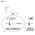
- the wireless LAN terminal 200 When the wireless LAN terminal 200 is disposed in the inside 10 of a communication area of the access point 100, the wireless LAN terminal 200 searches (scans) for the access point 100, performs a belonging process on the detected access point 100 to belong to the access point 100 (belonging state). When the wireless LAN terminal 200 is moved to the outside 12 of a communication area of the access point 100, the wireless LAN terminal 200 is then in the state of the outside service area of the access point 100 (non-belonging state).
- Two scanning methods that is, a passive scanning method and an active scanning method are used to scan for the access point 100.
- the former continuously performs a receiving operation for a predetermined amount of time and checks whether there is a desired access point 100 on the basis of the received beacon signal.
- the latter transmits a probe request signal and checks whether there is a desired access point 100 on the basis of a probe response signal from the access point 100.
- an SSID such as the identifier of the access point 100, needs to be included in the beacon signal.
- the SSID is included in the probe request signal, and the access point 100 receiving the SSID transmits a response only when its SSID is identical to the received SSID. Therefore, the SSID does not need to be included in the probe response signal from the access point 100.
- the former and the latter are different from each other in this point.
- Fig. 4 is a diagram illustrating the structure of the beacon signal that is periodically transmitted from the access point 100 according to this exemplary embodiment.
- the beacon signal includes various information items for allowing the wireless LAN terminal 200 to belong to the access point 100 and various information items for synchronization after belonging to the access point.
- the beacon signal includes, for example, a Mac header 400 and a frame body 401.
- the frame body 401 includes an SSID 403.
- the SSID is an identification information of the access point 100 and is used when the wireless LAN terminal 200 belongs to the access point 100.
- the beacon signal does not include the SSID 403 from the viewpoint of security.
- the wireless LAN terminal 200 performs a scanning operation to periodically search the access point 100 in the state without belonging to the access point 100 (outside service area state). In this case, first, the wireless LAN terminal performs a passive scanning operation at each channel to check whether there is a beacon signal periodically transmitted from the access point 100 and then performs an active scanning operation.
- the passive scanning operation When it is checked whether there is a beacon signal by the passive scanning operation, it is possible to determine only whether there is a beacon signal without sensing information items, such as the Service Set IDentifier (SSID) included in the beacon signal. In addition, when it has confirmed that there is a beacon signal by the passive scanning method, the passive scanning operation is not performed at the other channels and only the active scanning operation is then performed at these channels.
- SSID Service Set IDentifier
- the wireless LAN terminal 200 in the outside service area state performs the passive scanning operation so as to perform periodical scanning and receives the beacon signal from the access point 100.
- the wireless LAN terminal 200 that is disposed in the inside 10 of the communication area of the access point confirms the beacon signal, performs the active scanning operation, and attempts to belong to the access point 100.
- the wireless LAN terminal 200 in the outside service area state performs the passive scanning operation so as to perform periodical scanning, but cannot receive the beacon signal from the access point 100. Therefore, it is difficult for the wireless LAN terminal 200 to check whether there is a beacon signal, and the active scanning operation is not performed.
- Fig. 2 is a block diagram illustrating the configurations of the access point 100 and the wireless LAN terminal 200 according to this exemplary embodiment.
- the configurations of components that are not related to the essence of the invention are not shown.
- a speaker, a microphone, and a voice processing unit of the wireless LAN terminal 200 are not shown.
- the access point 100 includes a wired communication unit 101, a control unit 103, a storage unit 105, a wireless LAN wireless communication unit 107, and an antenna 109.
- the wired communication unit 101 provides an interface for connection to the LAN 1.
- the control unit 103 is connected to the wired communication unit 101, the storage unit 105, and the wireless LAN wireless communication unit 107 through a bus 111, and controls all the components of the access point 100 and the overall operation of the access point 100.
- the storage unit 105 includes a storage area that stores various set values of the access point 100 and a buffer that stores communication data.
- the wireless LAN wireless communication unit 107 provides a communication interface for connection to the wireless LAN terminal 200 through the antenna 109.
- the wireless LAN terminal 200 includes a control unit 201, a storage unit 203, a wireless LAN wireless communication unit 205, an antenna 207, a display unit 209, an operating unit 211, and a power supply unit 213.
- the control unit 201 is connected to the storage unit 203, the wireless LAN wireless communication unit 205, the display unit 209, the operating unit 211, and the power supply unit 213 through a bus 215, and controls all the components of the wireless LAN terminal 200 and the overall operation of the wireless LAN terminal 200.
- the storage unit 203 includes an area that stores programs executed by the control unit 201, a work area that is used by the control unit 201 when the control unit 201 executes the programs, a storage area that stores various set values of the wireless LAN terminal 200, and a buffer that stores communication data.
- the wireless LAN wireless communication unit 205 provides a communication interface for connection to the access point 100 through the antenna 207.
- the display unit 209 is, for example, a Liquid Crystal Display (LCD) or an organic Electro-Luminescence (EL) display, and displays various screens.
- the operating unit 211 includes, for example, operating keys, a switch, a dial, a touch pen, and a touch panel, and is operated by the user to accept the user' s operations.
- the display unit 209 and the operating unit 211 form a user interface.
- the power supply unit 213 controls the power which is supplied to the wireless LAN terminal 200.
- Fig. 3 is a functional block diagram schematically illustrating the wireless LAN terminal 200 according to this exemplary embodiment.
- Each constitutional element of the wireless LAN terminal 200 is realized by any combination of hardware and software based on a CPU of any computer, a memory, a program that is loaded on the memory to implement the components shown in the drawings, a memory unit such as a hard disk that stores the program, and an interface for network connection. It will be understood by those skilled in the art that a diversity of variations of a method and device of realizing the components may be made.
- Each of drawings to be described hereinafter does not depict hardware-based constructions but function-based blocks.
- the wireless LAN terminal 200 includes a profile storage unit 305 that stores the profile information of a predetermined access point 100 ( Fig. 2 ), a unit (a scanning interval setting unit 311 and a scanning setting unit 313) that sets a channel to be scanned on the basis of a scanning period and the profile information, a passive scanning unit 315 that performs the passive scanning operation at the set channel and detects the beacon signal transmitted from the access point, and an active scanning unit 317 that performs the active scanning operation at the set channel. Before the active scanning unit 317 performs the active scanning operation at the set channel, the passive scanning unit 315 performs the passive scanning operation at the set channel for each scanning period and detects the beacon signal transmitted from the access point 100 ( Fig. 2 ). Then, the active scanning unit 317 performs the active scanning operation at the set channel and searches for the access point.
- a profile storage unit 305 that stores the profile information of a predetermined access point 100 ( Fig. 2 )
- a unit a scanning interval setting unit 311 and a scanning setting
- the passive scanning operation by the passive scanning unit 315 is interrupted, and only the active scanning operation by the active scanning unit 317 is performed.
- the wireless LAN terminal 200 includes a profile acquiring unit 301, a profile registration accepting unit 303, a profile storage unit 305, a detecting unit 307, a timer 309, a scanning interval setting unit 311, a scanning setting unit 313, a passive scanning unit 315, an active scanning unit 317, and a belonging processing unit 319.
- control unit 201 performs various processing operations according to the computer programs stored in the storage unit 203 to implement the functions of the above units 301 to 319.
- Fig. 5 is a diagram illustrating an exemplary example of the structure of the profile storage unit 305.
- the profile storage unit 305 includes a profile list 330 of the access point 100, which is an access candidate, as shown in Fig. 5 .
- a plurality of profile lists 330 may be stored in the profile storage unit 305.
- the profile list 330 includes a profile name 331 for identifying the list and an SSID 333 of the access point 100.
- the profile list 330 includes a communication channel setting field 335 and various network setting information required for the wireless LAN terminal, which will not be described since they are not related to the essence of the invention.
- the profile acquiring unit 301 searches the surroundings through the wireless LAN wireless communication unit 205 shown in Fig. 2 , acquires information from the access point 100, which is an access candidate, and automatically adds the profile list to the profile storage unit 305.
- the access point 100 shown in Fig. 2 may store the profile information in the storage unit 105 and periodically transmit the profile information through the wireless LAN wireless communication unit 107 shown in Fig. 2 .
- Wi-Fi Protected Setup (trademark) of WI-FI ALLIANCE (registered trademark) is used as a method of automatically acquiring and setting up the profile list.
- the access point 100 may include an operating unit that accepts an instruction to transmit profile information.
- the operating unit When the operating unit is operated by the user, the operating unit may accept the transmission instruction, and then the access point 100 may transmit the profile information.
- the wireless LAN terminal 200 then may receive the profile information and automatically sets the profile information.
- AirStation One-Touch Secure System (AOSS) (registered trademark) of Buffalo Inc. may be used for this automatic setting operation.
- the profile registration accepting unit 303 displays a profile list setting screen (not shown) on the display unit 209 so as to make the user perform a setting operation.
- the profile registration accepting unit 303 then may store the profile list in the profile storage unit 305.
- the detecting unit 307 detects that the wireless LAN terminal becomes the state of the outside service area of the access point 100 in case when the wireless LAN wireless communication unit 205 becomes impossible to receive the beacon signal for a predetermined time or more.
- the detecting unit 307 notifies this to the scanning interval setting unit 311, the passive scanning unit 315, and the belonging processing unit 319.
- the timer 309 is a measuring unit that measures the time when the detecting unit 307 monitors the reception of the beacon signal or the scanning interval set by the scanning interval setting unit 311.
- the scanning interval setting unit 311 sets a scanning interval at which the passive scanning unit 315 performs the passive scanning operation.
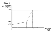
- Fig. 7 is a diagram illustrating the setting of the scanning period of the wireless LAN terminal 200 according to this exemplary embodiment, which will be described with reference to Figs. 3 and 7 .
- the wireless LAN terminal 200 further includes the belonging processing unit 319 that makes the wireless LAN terminal 200 belong to the access point 100 when the active scanning unit 317 detects the access point 100 and the detecting unit 307 which are receiving the transmitted beacon signals periodically transmitted from the access point 100 while the wireless LAN terminal belongs to the access point, and detects that the wireless LAN terminal becomes an outside service area state when the wireless LAN terminal 200 becomes impossible to receive the beacon signal for a predetermined time or more and.
- the setting unit sets the scanning period to an initial scanning interval T0 immediately after the detecting unit 307 detects that the wireless LAN terminal is in the outside service area state, and makes the scanning interval ⁇ T increase at a first increasing rate (( ⁇ T1- ⁇ T0) /t1) according to an elapsed time t.
- the setting unit makes the scanning interval ⁇ T increase at a second increasing rate (( ⁇ T2- ⁇ T1) /(t2-t1)) which is more than the first increasing rate according to the elapsed time t. In this way, the setting unit sets the scanning period.
- the wireless LAN terminal 200 when the wireless LAN terminal 200 does not belong to the access point 100 (outside service area state), the wireless LAN terminal 200 periodically performs an operation of searching (scanning) for the access point 100 for the scanning period of the scanning interval ⁇ T.
- the power supply unit 213 of the wireless LAN terminal 200 supplies power to the wireless LAN wireless communication unit 205 during scanning.
- the power supply unit 213 cuts the supply of power to the wireless LAN wireless communication unit 205 until the next scanning operation.
- the scanning interval setting unit 311 sets the scanning interval ⁇ T such that it gradually increases with the elapsed time t.
- the scanning interval setting unit 311 makes the scanning interval ⁇ T increase at the first increasing rate (( ⁇ T1- ⁇ T0)/t1) during the period from the time when the wireless LAN terminal becomes the outside service area state to the elapsed time t1, and makes the scanning interval ⁇ T increase at the second increasing rate (( ⁇ T2- ⁇ T1)/(t2-t1)) which is more than the first increasing rate when the elapsed time becomes t1.
- the scanning interval ⁇ T thus changed is intended to make the scanning interval ⁇ T set to be short so that the belonging information can be rapidly recovered, immediately after the wireless LAN terminal becomes in the outside service area state, and to make the scanning interval ⁇ T set to be long in order to reduce power consumption when the wireless LAN terminal cannot become the belonging state for some time.
- the scanning interval ⁇ T can be set to be longer. Therefore, at the beginning of the outside service area state, the scanning is performed at a short scanning interval so that it is possible to recover as quickly as possible. In a case when a predetermined time has elapsed after the wireless LAN terminal becomes the outside service area state, it is possible to continuously perform the scanning with high efficiency while reducing power consumption.
- the scan setting unit 313 checks the profile list 330 ( Fig. 5 ) with reference to the profile storage unit 305, and sets the number of channels to be scanned and each channel. When there is a plurality of profile lists in the profile storage unit 305, the scan setting unit 313 displays the profile lists on the display unit 209 such that the user may view the profile lists. Then, the user operates the operating unit 211 to select one of the profile lists to be used for wireless communication. The instruction of the selected list may be then accepted by the operating unit 211.
- the passive scanning unit 315 performs the passive scanning operation at the scanning interval ⁇ T set by the scanning interval setting unit 311, and detects the beacon signal transmitted from the access point 100.
- the detection of the beacon signal may be performed by the passive scanning unit 315 by determining only whether there is a beacon signal or not without detecting information items such as an SSID.
- the passive scanning unit 315 performs the passive scanning operation at the channel set by the scan setting unit 313. When a plurality of channels are set, the passive scanning unit 315 repeatedly performs the passive scanning operation while sequentially changing the channels until the beacon signal is detected.
- the active scanning unit 317 performs the active scanning operation at the channel set by the scan setting unit 313 in response to the detection of the beacon signal by the passive scanning unit 315.
- the active scanning unit 317 scans all the channels while sequentially changing the channel.
- the active scanning unit 317 selects a target access point 100 according to predetermined rules. For example, the active scanning unit 317 may select an access point with a high-intensity signal or a high Signal to Noise Ratio (SNR).
- SNR Signal to Noise Ratio
- the belonging processing unit 319 performs belonging processing on the access point 100 selected by the active scanning unit 317 through the wireless LAN wireless communication unit 205. Specifically, the belonging processing unit 319 transmits an association request to the access point 100, receives an association response from the access point 100, and then moves to the belonging state. While the wireless LAN terminal belongs to the access point 100, the aforementioned detecting unit 307 receives the beacon signal from the access point 100 and is synchronized with the beacon signal. When the detecting unit 307 does not detect the beacon signal for a predetermined time or more, the wireless LAN terminal then moves the outside service area state.
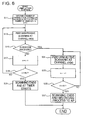
- FIG. 6 is a flowchart illustrating an exemplary example of the search operation for the access point 100 in the wireless LAN terminal 200 according to this exemplary embodiment. It will be described herein later with reference to Figs. 2 , 3 , 5 , and 6 .
- the method of searching for the access point 100 using the wireless LAN terminal 200 including the profile storage unit 305 ( Fig. 3 ) that stores profile information including the channel information of a predetermined access point 100, a setting unit (the scanning interval setting unit 311 and the scanning setting unit 313 shown in Fig. 3 ) that sets a channel to be scanned on the basis of the scanning period and the profile information, the passive scanning unit 315 ( Fig. 3 ) that performs the passive scanning operation at the set channel and detects the beacon signal, and the active scanning unit 317 that performs the active scanning operation at the set channel.
- the profile storage unit 305 Fig. 3
- a setting unit the scanning interval setting unit 311 and the scanning setting unit 313 shown in Fig. 3
- the passive scanning unit 315 that performs the passive scanning operation at the set channel and detects the beacon signal
- the active scanning unit 317 that performs the active scanning operation at the set channel.
- the passive scanning unit 315 performs the passive scanning operation at the set channel for each scanning period (S13).
- the active scanning unit 317 performs the active scanning operation at the set channel (S31) and searches for the access point.
- the scanning interval setting unit 311 shown in Fig. 3 accesses the profile storage unit 305 shown in Fig. 3 , reads the profile list 330 ( Fig. 5 ), and sets the number of channels to be scanned and each channel (S11). If necessary, the profile list 330 ( Fig. 5 ) may be displayed on the display unit 209 so as to present the profile list to the user and make the user to select one of the profile lists 330. Then, the operating unit 211 ( Fig. 2 ) may accept the selected profile list 330. When the profile list 330 shown in Fig.
- ch(0) 36ch
- ch(1) 40ch
- ch(2) 44ch
- ch(3) 48ch.
- a counter variable n is initialized at 0.
- the flow of this process is activated at the scanning time intervals ⁇ T.
- the process in the step S11 is performed when the wireless LAN terminal 200 searches for the access point 100.
- the process in the step S11 may be bypassed as long as an instruction to change the profile is not accepted from the user.
- the power supply unit 213 shown in Fig. 2 does not supply power to the wireless LAN wireless communication unit 205 shown in Fig. 2 .
- the scanning interval setting unit 311 shown in Fig. 3 detects the scanning interval ⁇ T and notifies the passive scanning unit 315 shown in Fig. 3 .
- the passive scanning unit 315 shown in Fig. 3 performs the passive scanning operation at the channel ch (n) (S13).
- the power supply unit 213 shown in Fig. 2 supplies power to the wireless LAN wireless communication unit 205 shown in Fig. 2 .
- the power supply unit 213 shown in Fig. 2 supplies power to the wireless LAN wireless communication unit 205 shown in Fig. 2 .
- the power supply unit 213 shown in Fig. 2 stops the supply of power to the wireless LAN wireless communication unit 205 shown in Fig. 2 until the next scanning period.
- the passive scanning unit 315 shown in Fig. 3 detects the beacon signal (S15: YES)
- the process proceeds to the step S31.
- the beacon signal is not detected (S15: NO)
- the counter variable n is incremented (S17), and it is checked whether all the channels are completely scanned (S19).
- the process returns to the step S13.
- the scanning interval setting unit 311 shown in Fig. 3 is instructed to start to count the scanning interval ⁇ T.
- the scanning interval setting unit 311 shown in Fig. 3 sets the scanning interval, as described above, such that scanning may be performed again after the next scanning interval ⁇ T.
- the power supply unit 213 shown in Fig. 2 stops the supply of power to the wireless LAN wireless communication unit 205 shown in Fig. 2 .
- the belonging processing unit 319 shown in Fig. 3 then makes the wireless LAN terminal belong to the detected access point 100 (S37).
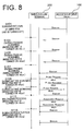
- FIG. 8 is a diagram illustrating an exemplary example of the sequence of the search operation between the wireless LAN terminal 200 and the access point 100 in the wireless LAN system according to this exemplary embodiment. It will be described hereinafter with reference to Figs. 2 , 3 , and 8 .
- the counter variable n is initialized at 0.
- the power supply unit 213 shown in Fig. 2 starts to supply power to the wireless LAN wireless communication unit 205 shown in Fig. 2 .
- the passive scanning operation by the passive scanning unit 315 shown in Fig. 3 is not performed, but only the active scanning operation by the active scanning unit 317 shown in Fig. 3 is performed.
- the belonging processing unit 319 shown in Fig. 3 performs the belonging processing on the access point 100 with the channel 44 through the wireless LAN wireless communication unit 205 ( Fig. 2 ) (S113). Then, the wireless LAN terminal 200 belongs to the access point 100 with the channel 44 (S115).
- the detecting unit 307 shown in Fig. 3 normally receives the beacon signal from the access point 100, and is synchronized with the signal. When the detecting unit 307 shown in Fig. 3 does not receive the beacon signal from the access point 100 for a predetermined time or more, the state of the belonging to the access point 100 is released to become the outside service area (not shown).
- the passive scanning operation is performed to detect the beacon signal before the active scanning operation is performed. In this way, it is possible to recognize that the terminal is indoors. After it is recognized that the terminal is indoors, it is possible to perform the active scanning operation. Therefore, it is possible to use the terminal without considering whether the terminal is indoors or outdoors.
- the beacon signal After the beacon signal is detected, only the active scanning operation is performed, and the passive scanning operation that is performed at a predetermined time interval is interrupted. Therefore, it is possible to search an access point at a high speed and thus reduce the search time.
- the interval of the scanning period may be set to become longer. Therefore, it is possible to perform scanning for a short scanning period in the initial state in which the wireless LAN terminal becomes the outside service area state, thereby recovering as quickly as possible.
- a predetermined time has elapsed in the outside service area state, it is possible to continuously perform scanning with high efficiency while reducing power consumption.
- a wireless LAN terminal may further include a determining unit (not shown) that determines whether the channels in which the profile information of the profile storage unit 305 is set include a specific channel that is allowed to be used outdoors.
- the determining unit determines that the channels include the specific channel, the passive scanning operation may not be performed by the passive scanning unit 315 shown in Fig. 3 , but only the active scanning operation may be performed by the active scanning unit 317 shown in Fig. 3 .
- the terminal In the 2.4 GHz band used in the IEEE 802.11b/g Standard, the terminal is allowed to be used outdoors. Therefore, when the channels used in the IEEE 802.11b/g Standard are included in the profile list of the profile storage unit 305, the active scanning operation may be unconditionally performed at these channels. When the active scanning operation is performed without performing the passive scanning operation, the setting of the period for which the active scanning operation is performed may be performed at each scanning interval ⁇ T set by the scanning interval setting unit 311 as described above.
Landscapes
- Engineering & Computer Science (AREA)
- Computer Security & Cryptography (AREA)
- Computer Networks & Wireless Communication (AREA)
- Signal Processing (AREA)
- Mobile Radio Communication Systems (AREA)
- Small-Scale Networks (AREA)
Applications Claiming Priority (2)
| Application Number | Priority Date | Filing Date | Title |
|---|---|---|---|
| JP2007198878 | 2007-07-31 | ||
| PCT/JP2008/001894 WO2009016800A1 (fr) | 2007-07-31 | 2008-07-15 | Terminal de réseau local sans fil et procédé de recherche de point d'accès |
Publications (3)
| Publication Number | Publication Date |
|---|---|
| EP2184892A1 true EP2184892A1 (fr) | 2010-05-12 |
| EP2184892A4 EP2184892A4 (fr) | 2013-08-28 |
| EP2184892B1 EP2184892B1 (fr) | 2016-12-21 |
Family
ID=40304044
Family Applications (1)
| Application Number | Title | Priority Date | Filing Date |
|---|---|---|---|
| EP08776853.7A Not-in-force EP2184892B1 (fr) | 2007-07-31 | 2008-07-15 | Terminal de réseau local sans fil et procédé de recherche de point d'accès |
Country Status (5)
| Country | Link |
|---|---|
| US (1) | US8570942B2 (fr) |
| EP (1) | EP2184892B1 (fr) |
| JP (1) | JP5392845B2 (fr) |
| CN (1) | CN101772980B (fr) |
| WO (1) | WO2009016800A1 (fr) |
Cited By (4)
| Publication number | Priority date | Publication date | Assignee | Title |
|---|---|---|---|---|
| GB2474111A (en) * | 2009-09-30 | 2011-04-06 | Apple Inc | Secure wireless networking using solicited access |
| US8464061B2 (en) | 2010-08-30 | 2013-06-11 | Apple Inc. | Secure wireless link between two devices using probes |
| US8830866B2 (en) | 2009-09-30 | 2014-09-09 | Apple Inc. | Methods and apparatus for solicited activation for protected wireless networking |
| WO2017052952A1 (fr) * | 2015-09-25 | 2017-03-30 | Qualcomm Incorporated | Optimisations de balayage de canal à sélection de fréquence dynamique |
Families Citing this family (48)
| Publication number | Priority date | Publication date | Assignee | Title |
|---|---|---|---|---|
| JP5200833B2 (ja) * | 2008-09-30 | 2013-06-05 | 株式会社リコー | 無線通信システム、端末局、無線通信方法、プログラム、および記録媒体 |
| JP5332840B2 (ja) * | 2009-04-08 | 2013-11-06 | ソニー株式会社 | 無線通信装置、無線通信システム、無線通信方法及びプログラム |
| US8300613B2 (en) * | 2009-06-05 | 2012-10-30 | Intel Corporation | Techniques for detecting beacons on wireless channels |
| CN101909311A (zh) * | 2009-06-08 | 2010-12-08 | 鸿富锦精密工业(深圳)有限公司 | 测试手机无线上网功能的方法 |
| US8363630B2 (en) | 2009-08-11 | 2013-01-29 | Intel Corporation | Device, system and method of scanning a wireless communication frequency band |
| AU2009352394B2 (en) | 2009-09-09 | 2013-08-15 | Lg Electronics Inc. | Method of channel scanning in wireless local area network system |
| JP5688089B2 (ja) | 2009-10-21 | 2015-03-25 | エルジー エレクトロニクス インコーポレイティド | TVWS(TVWhiteSpace)で存在するネットワークをスキャニングするための方法及び装置 |
| JP5366213B2 (ja) * | 2010-03-03 | 2013-12-11 | Necエンジニアリング株式会社 | 無線通信システム、基地局検索周期の設定方法及び無線基地局 |
| CN105530709B (zh) | 2010-03-12 | 2019-07-12 | Lg电子株式会社 | Wlan系统中的设备 |
| JP5053400B2 (ja) * | 2010-03-15 | 2012-10-17 | 株式会社バッファロー | 無線lan装置、プロトコル実行方法及びそのプログラム |
| WO2011115449A2 (fr) | 2010-03-19 | 2011-09-22 | Lg Electronics Inc. | Procédé et appareil permettant d'acquérir des informations sur le canal disponible dans un système de réseau local sans fil |
| JP5311502B2 (ja) * | 2010-03-31 | 2013-10-09 | 日本電気株式会社 | 無線通信装置およびそのアクセスポイント探索制御方法 |
| EP2556604B1 (fr) | 2010-04-07 | 2017-09-06 | LG Electronics Inc. | Procédé et système pour émettre et recevoir des informations de carte des fréquences libérées dans système de réseau local sans fil |
| AU2011262720B2 (en) | 2010-06-07 | 2013-11-21 | Lg Electronics Inc. | Method and apparatus for a station to operate within WLAN system |
| CN102378312A (zh) * | 2010-08-23 | 2012-03-14 | 国基电子(上海)有限公司 | 移动手持装置及其追踪定位方法 |
| US8548495B2 (en) * | 2010-09-08 | 2013-10-01 | Texas Instruments Incorporated | System and method for determining a position of a mobile wireless device by accessing access points alamanacs database |
| US9173139B2 (en) * | 2010-10-07 | 2015-10-27 | Lg Electronics Inc. | Method and Terminal for Quickly Searching for an Access Point |
| JP5472036B2 (ja) * | 2010-10-22 | 2014-04-16 | セイコーエプソン株式会社 | 無線通信装置、それを備えた周辺装置、及び無線通信方法 |
| TWI425856B (zh) * | 2010-10-27 | 2014-02-01 | Lanready Technologies Inc | Automatically establish a wireless network topology |
| KR20120068275A (ko) * | 2010-12-17 | 2012-06-27 | 삼성전자주식회사 | 휴대 단말기의 AP(Access Point) 접속 제어 방법 및 장치 |
| US8689123B2 (en) | 2010-12-23 | 2014-04-01 | Microsoft Corporation | Application reporting in an application-selectable user interface |
| JP2012217049A (ja) * | 2011-03-31 | 2012-11-08 | Fujitsu Ltd | プログラム、情報通信機器およびシステム |
| US9491607B2 (en) * | 2012-02-16 | 2016-11-08 | Apple Inc. | Wireless scan and advertisement in electronic devices |
| US9282449B2 (en) | 2012-03-01 | 2016-03-08 | Microsoft Technology Licensing, Llc | Peer-to-peer discovery |
| WO2013146565A1 (fr) * | 2012-03-30 | 2013-10-03 | ソニー株式会社 | Dispositif de terminal, procédé de communication, programme et système de communication |
| CN102711226A (zh) * | 2012-05-23 | 2012-10-03 | 中兴通讯股份有限公司 | Wifi接入点扫描方法及装置 |
| US8805423B2 (en) * | 2012-06-19 | 2014-08-12 | Qualcomm Incorporated | Adaptive passive scanning and/or active probing techniques for mobile device positioning |
| EP2680645B1 (fr) * | 2012-06-28 | 2015-09-09 | ST-Ericsson SA | Procédé et station mobile sans fil de balayage de balise dans un réseau local sans fil |
| JP6106270B2 (ja) | 2012-06-28 | 2017-03-29 | ケイティー コーポレーションKt Corporation | 無線lanシステムでアクセスポイントの検索方法 |
| CN103533604B (zh) * | 2012-07-03 | 2016-12-28 | 华为终端有限公司 | 无线保真网络中扫描接入点、信道选择方法、设备及系统 |
| KR101561117B1 (ko) | 2012-09-20 | 2015-10-16 | 주식회사 케이티 | 무선랜 시스템에서 능동 검색 방법 |
| CN104041134B (zh) | 2012-12-26 | 2018-09-28 | 华为技术有限公司 | 搜索无线局域网接入点的方法、装置及系统 |
| US9357473B2 (en) * | 2013-03-12 | 2016-05-31 | Qualcomm Incorporated | Adaptive wireless access point discovery |
| JP2014230110A (ja) * | 2013-05-23 | 2014-12-08 | Kddi株式会社 | 無線端末がアクセスポイントを発見するシステム、プログラム及び方法 |
| JP5673876B2 (ja) * | 2014-02-05 | 2015-02-18 | セイコーエプソン株式会社 | 無線通信装置、それを備えた周辺装置、及び無線通信方法 |
| KR101749677B1 (ko) * | 2015-07-27 | 2017-06-21 | 주식회사 케이티 | 출입 관리 서비스를 제공하는 사용자 단말, 출입 판단 서버 및 컴퓨터 프로그램 |
| CN105407473B (zh) * | 2015-10-22 | 2019-07-05 | 小米科技有限责任公司 | 无线局域网发现方法及装置 |
| CN105472006A (zh) * | 2015-12-10 | 2016-04-06 | 小米科技有限责任公司 | 文件传输方法、装置和系统 |
| JP6729112B2 (ja) | 2016-07-14 | 2020-07-22 | 富士通株式会社 | 情報処理方法、情報処理プログラム、情報処理装置及び情報処理システム |
| CN106507443B (zh) * | 2016-10-10 | 2019-03-15 | 珠海市魅族科技有限公司 | 服务集标识ssid的显示方法及装置 |
| JP6651674B2 (ja) | 2017-03-10 | 2020-02-19 | アルプスアルパイン株式会社 | 通信装置、通信方法及びプログラム |
| CN107846723B (zh) * | 2017-12-13 | 2020-04-24 | Oppo广东移动通信有限公司 | 无线局域网扫描方法、装置、计算机设备及存储介质 |
| BR112021013087A2 (pt) * | 2019-01-08 | 2021-09-21 | Sony Group Corporation | Dispositivo e método de comunicação |
| CN110234152B (zh) * | 2019-06-03 | 2021-06-18 | Oppo广东移动通信有限公司 | 信道扫描方法、装置、存储介质及电子设备 |
| CN111132273B (zh) * | 2020-01-03 | 2022-03-29 | 环鸿电子(昆山)有限公司 | 无线网络的被主动扫描转换方法及系统 |
| CN113518408A (zh) * | 2021-04-19 | 2021-10-19 | Tcl通讯(宁波)有限公司 | WiFi单信道扫描方法、装置、终端设备及存储介质 |
| CN113727323B (zh) * | 2021-07-28 | 2024-03-29 | 深圳市联洲国际技术有限公司 | 双频客户端的通信方法、设备、双频客户端和通信系统 |
| EP4376462A4 (fr) * | 2021-09-15 | 2024-11-27 | Samsung Electronics Co., Ltd. | Dispositif électronique et procédé pour réaliser une communication par l'intermédiaire d'un réseau privé virtuel, et support de stockage lisible par ordinateur |
Family Cites Families (23)
| Publication number | Priority date | Publication date | Assignee | Title |
|---|---|---|---|---|
| US5794146A (en) * | 1996-08-14 | 1998-08-11 | Sharp Microelectronics Technology, Inc. | System and method for conserving battery power in a mobile station searching to select a serving cell |
| JP3005509B2 (ja) | 1997-11-04 | 2000-01-31 | 静岡日本電気株式会社 | エリア判断方法並びにエリア判断回路及びそれを備えた無線選択呼出受信機 |
| KR100419617B1 (ko) * | 2002-02-19 | 2004-02-25 | 삼성전기주식회사 | 무선랜시스템에 있어서 무선랜카드의 운영 방법 |
| US7522906B2 (en) * | 2002-08-09 | 2009-04-21 | Wavelink Corporation | Mobile unit configuration management for WLANs |
| JP2004153394A (ja) | 2002-10-29 | 2004-05-27 | Tdk Corp | 無線端末装置、無線通信用アダプタ、コンピュータプログラムおよび無線通信方法 |
| US20040137905A1 (en) | 2003-01-09 | 2004-07-15 | Docomo Communications Laboratories Usa, Inc. | System and method for channel scanning in wireless networks |
| EP1623587A4 (fr) | 2003-05-14 | 2006-06-14 | Interdigital Tech Corp | Procede et systeme de gestion de reseau utilisant des mesures periodiques d'indicateurs |
| JP2005012539A (ja) | 2003-06-19 | 2005-01-13 | Nec Corp | 無線端末装置および基地局探索方法 |
| JP5080080B2 (ja) * | 2003-07-15 | 2012-11-21 | コーニンクレッカ フィリップス エレクトロニクス エヌ ヴィ | Wlanにおける高速アクティブスキャニングを行う方法、アクセスポイント、高速アクティブスキャニングシステム及び第1局 |
| JP2006013594A (ja) | 2004-06-22 | 2006-01-12 | Nec Corp | 無線lan通信システムおよび無線lan接続方法と無線lan端末装置 |
| CN1758547A (zh) * | 2004-10-04 | 2006-04-12 | 松下电器产业株式会社 | 收信装置、半导体集成电路、收发信装置、以及收信方法 |
| KR100689554B1 (ko) * | 2004-10-07 | 2007-03-02 | 삼성전자주식회사 | 광대역 무선 접속 통신 시스템에서 옥내 및 옥외 무선접속을 제공하는 장치 및 방법 |
| US7366511B2 (en) * | 2004-12-20 | 2008-04-29 | Nokia Corporation | Apparatus, and associated method, for facilitating network scanning by a WLAN terminal operable in a multiple-network WLAN system |
| JP5002149B2 (ja) * | 2005-02-03 | 2012-08-15 | キヤノン株式会社 | 通信装置及び通信方法 |
| US20060215621A1 (en) * | 2005-03-24 | 2006-09-28 | Research In Motion Limited | Scanning for wireless local area networks |
| JP4735022B2 (ja) | 2005-04-27 | 2011-07-27 | 日本電気株式会社 | 無線lan端末、無線lan端末のスキャン動作方法およびスキャン動作プログラム |
| CN100490408C (zh) | 2005-11-24 | 2009-05-20 | 鸿富锦精密工业(深圳)有限公司 | 接入点及其建立无线分布系统连线的方法 |
| JP2007198878A (ja) | 2006-01-26 | 2007-08-09 | Hara Doki Kk | 表示装置のケースへの装着方法 |
| US8023478B2 (en) * | 2006-03-06 | 2011-09-20 | Cisco Technology, Inc. | System and method for securing mesh access points in a wireless mesh network, including rapid roaming |
| US20070223432A1 (en) * | 2006-03-21 | 2007-09-27 | Badarinath Sharma K | Wi-Fi network connection management using location specific information |
| US9319967B2 (en) * | 2006-05-15 | 2016-04-19 | Boingo Wireless, Inc. | Network access point detection and use |
| US8165101B2 (en) * | 2006-09-29 | 2012-04-24 | Microsoft Corporation | Automatic detection of hidden networks |
| US7969909B2 (en) * | 2007-01-18 | 2011-06-28 | Research In Motion Limited | System and method for seeking a wireless network for a wireless device |
-
2008
- 2008-07-15 WO PCT/JP2008/001894 patent/WO2009016800A1/fr not_active Ceased
- 2008-07-15 EP EP08776853.7A patent/EP2184892B1/fr not_active Not-in-force
- 2008-07-15 CN CN200880101501.1A patent/CN101772980B/zh not_active Expired - Fee Related
- 2008-07-15 JP JP2009525271A patent/JP5392845B2/ja not_active Expired - Fee Related
- 2008-07-15 US US12/670,336 patent/US8570942B2/en active Active
Cited By (7)
| Publication number | Priority date | Publication date | Assignee | Title |
|---|---|---|---|---|
| GB2474111A (en) * | 2009-09-30 | 2011-04-06 | Apple Inc | Secure wireless networking using solicited access |
| GB2474111B (en) * | 2009-09-30 | 2012-05-16 | Apple Inc | Methods and apparatus for solicited activation for protected wireless networking |
| US8830866B2 (en) | 2009-09-30 | 2014-09-09 | Apple Inc. | Methods and apparatus for solicited activation for protected wireless networking |
| US8873523B2 (en) | 2009-09-30 | 2014-10-28 | Apple Inc. | Methods and apparatus for solicited activation for protected wireless networking |
| US8464061B2 (en) | 2010-08-30 | 2013-06-11 | Apple Inc. | Secure wireless link between two devices using probes |
| WO2017052952A1 (fr) * | 2015-09-25 | 2017-03-30 | Qualcomm Incorporated | Optimisations de balayage de canal à sélection de fréquence dynamique |
| US9973969B2 (en) | 2015-09-25 | 2018-05-15 | Qualcomm Incorporated | Dynamic frequency selection channel scan optimizations |
Also Published As
| Publication number | Publication date |
|---|---|
| JPWO2009016800A1 (ja) | 2010-10-14 |
| WO2009016800A1 (fr) | 2009-02-05 |
| CN101772980A (zh) | 2010-07-07 |
| US8570942B2 (en) | 2013-10-29 |
| US20100195595A1 (en) | 2010-08-05 |
| EP2184892B1 (fr) | 2016-12-21 |
| CN101772980B (zh) | 2013-08-14 |
| EP2184892A4 (fr) | 2013-08-28 |
| JP5392845B2 (ja) | 2014-01-22 |
Similar Documents
| Publication | Publication Date | Title |
|---|---|---|
| EP2184892B1 (fr) | Terminal de réseau local sans fil et procédé de recherche de point d'accès | |
| EP2046091B1 (fr) | Proximité de l'équipement d'utilisateur pour un réseau local domestique | |
| EP1933502A1 (fr) | Dispositif de communication mobile | |
| KR101719365B1 (ko) | 영상 통화 방법 및 장치 | |
| CN101184332B (zh) | 无线通信转交处理方法及系统、便携式电子装置 | |
| KR102172046B1 (ko) | 무선 통신 시스템에서 접속 포인트 스캔 방법 및 장치 | |
| KR20090130981A (ko) | 듀얼 모드를 지원하는 이동통신 단말기의 동작 방법 및장치 | |
| KR101288865B1 (ko) | 통신 방법 및 무선기기 | |
| KR101724020B1 (ko) | 휴대용 단말기에서 전력 소모를 줄이기 위한 장치 및 방법 | |
| CN105722153B (zh) | 用于ce-mtc ue的小区重选方法 | |
| JP4407214B2 (ja) | 無線lanシステム | |
| JP2005012539A (ja) | 無線端末装置および基地局探索方法 | |
| EP2733992B1 (fr) | Appareil et procédé de connexion à un point d'accès dans un terminal portable | |
| JP2011114600A (ja) | 通信端末装置及びプログラム | |
| EP4224909A1 (fr) | Procédé de modification de zone de travail, terminal et dispositif côté réseau | |
| JP6075641B2 (ja) | 無線通信機器及び通信方法 | |
| KR101834091B1 (ko) | 영상 통화 방법 및 장치 | |
| KR100661181B1 (ko) | 무선통신규격 자동변경기능을 지원하는 무선단말장치 및그 방법 | |
| JP2011176539A (ja) | 携帯端末装置及び位置管理システム | |
| KR101943414B1 (ko) | 영상 통화 방법 및 장치 | |
| JP4974142B2 (ja) | 無線通信端末及び無線通信方法 | |
| EP2733993B1 (fr) | Appareil et procédé de connexion à une resource de communication de zone locale dans un terminal portable | |
| CN112367688A (zh) | 一种选网的方法、终端设备及计算机可读存储介质 | |
| KR20080042272A (ko) | 휴대용 단말기에서 유엠에이 망 수동 연결 방법 및 장치 | |
| JP2003219480A (ja) | 移動体通信機器および表示制御方法 |
Legal Events
| Date | Code | Title | Description |
|---|---|---|---|
| PUAI | Public reference made under article 153(3) epc to a published international application that has entered the european phase |
Free format text: ORIGINAL CODE: 0009012 |
|
| 17P | Request for examination filed |
Effective date: 20100129 |
|
| AK | Designated contracting states |
Kind code of ref document: A1 Designated state(s): AT BE BG CH CY CZ DE DK EE ES FI FR GB GR HR HU IE IS IT LI LT LU LV MC MT NL NO PL PT RO SE SI SK TR |
|
| AX | Request for extension of the european patent |
Extension state: AL BA MK RS |
|
| DAX | Request for extension of the european patent (deleted) | ||
| REG | Reference to a national code |
Ref country code: DE Ref legal event code: R079 Ref document number: 602008048008 Country of ref document: DE Free format text: PREVIOUS MAIN CLASS: H04L0012280000 Ipc: H04W0048160000 |
|
| RIC1 | Information provided on ipc code assigned before grant |
Ipc: H04W 48/16 20090101AFI20130709BHEP |
|
| A4 | Supplementary search report drawn up and despatched |
Effective date: 20130725 |
|
| 17Q | First examination report despatched |
Effective date: 20150923 |
|
| RAP1 | Party data changed (applicant data changed or rights of an application transferred) |
Owner name: LENOVO INNOVATIONS LIMITED (HONG KONG) |
|
| GRAP | Despatch of communication of intention to grant a patent |
Free format text: ORIGINAL CODE: EPIDOSNIGR1 |
|
| INTG | Intention to grant announced |
Effective date: 20160728 |
|
| STAA | Information on the status of an ep patent application or granted ep patent |
Free format text: STATUS: GRANT OF PATENT IS INTENDED |
|
| GRAS | Grant fee paid |
Free format text: ORIGINAL CODE: EPIDOSNIGR3 |
|
| GRAA | (expected) grant |
Free format text: ORIGINAL CODE: 0009210 |
|
| STAA | Information on the status of an ep patent application or granted ep patent |
Free format text: STATUS: THE PATENT HAS BEEN GRANTED |
|
| AK | Designated contracting states |
Kind code of ref document: B1 Designated state(s): AT BE BG CH CY CZ DE DK EE ES FI FR GB GR HR HU IE IS IT LI LT LU LV MC MT NL NO PL PT RO SE SI SK TR |
|
| REG | Reference to a national code |
Ref country code: GB Ref legal event code: FG4D |
|
| REG | Reference to a national code |
Ref country code: CH Ref legal event code: EP |
|
| REG | Reference to a national code |
Ref country code: IE Ref legal event code: FG4D |
|
| REG | Reference to a national code |
Ref country code: AT Ref legal event code: REF Ref document number: 856437 Country of ref document: AT Kind code of ref document: T Effective date: 20170115 |
|
| REG | Reference to a national code |
Ref country code: DE Ref legal event code: R096 Ref document number: 602008048008 Country of ref document: DE |
|
| PG25 | Lapsed in a contracting state [announced via postgrant information from national office to epo] |
Ref country code: LV Free format text: LAPSE BECAUSE OF FAILURE TO SUBMIT A TRANSLATION OF THE DESCRIPTION OR TO PAY THE FEE WITHIN THE PRESCRIBED TIME-LIMIT Effective date: 20161221 |
|
| REG | Reference to a national code |
Ref country code: NL Ref legal event code: FP |
|
| REG | Reference to a national code |
Ref country code: LT Ref legal event code: MG4D |
|
| PG25 | Lapsed in a contracting state [announced via postgrant information from national office to epo] |
Ref country code: NO Free format text: LAPSE BECAUSE OF FAILURE TO SUBMIT A TRANSLATION OF THE DESCRIPTION OR TO PAY THE FEE WITHIN THE PRESCRIBED TIME-LIMIT Effective date: 20170321 Ref country code: SE Free format text: LAPSE BECAUSE OF FAILURE TO SUBMIT A TRANSLATION OF THE DESCRIPTION OR TO PAY THE FEE WITHIN THE PRESCRIBED TIME-LIMIT Effective date: 20161221 Ref country code: LT Free format text: LAPSE BECAUSE OF FAILURE TO SUBMIT A TRANSLATION OF THE DESCRIPTION OR TO PAY THE FEE WITHIN THE PRESCRIBED TIME-LIMIT Effective date: 20161221 Ref country code: GR Free format text: LAPSE BECAUSE OF FAILURE TO SUBMIT A TRANSLATION OF THE DESCRIPTION OR TO PAY THE FEE WITHIN THE PRESCRIBED TIME-LIMIT Effective date: 20170322 |
|
| REG | Reference to a national code |
Ref country code: AT Ref legal event code: MK05 Ref document number: 856437 Country of ref document: AT Kind code of ref document: T Effective date: 20161221 |
|
| PG25 | Lapsed in a contracting state [announced via postgrant information from national office to epo] |
Ref country code: FI Free format text: LAPSE BECAUSE OF FAILURE TO SUBMIT A TRANSLATION OF THE DESCRIPTION OR TO PAY THE FEE WITHIN THE PRESCRIBED TIME-LIMIT Effective date: 20161221 Ref country code: HR Free format text: LAPSE BECAUSE OF FAILURE TO SUBMIT A TRANSLATION OF THE DESCRIPTION OR TO PAY THE FEE WITHIN THE PRESCRIBED TIME-LIMIT Effective date: 20161221 |
|
| PG25 | Lapsed in a contracting state [announced via postgrant information from national office to epo] |
Ref country code: EE Free format text: LAPSE BECAUSE OF FAILURE TO SUBMIT A TRANSLATION OF THE DESCRIPTION OR TO PAY THE FEE WITHIN THE PRESCRIBED TIME-LIMIT Effective date: 20161221 Ref country code: SK Free format text: LAPSE BECAUSE OF FAILURE TO SUBMIT A TRANSLATION OF THE DESCRIPTION OR TO PAY THE FEE WITHIN THE PRESCRIBED TIME-LIMIT Effective date: 20161221 Ref country code: RO Free format text: LAPSE BECAUSE OF FAILURE TO SUBMIT A TRANSLATION OF THE DESCRIPTION OR TO PAY THE FEE WITHIN THE PRESCRIBED TIME-LIMIT Effective date: 20161221 Ref country code: CZ Free format text: LAPSE BECAUSE OF FAILURE TO SUBMIT A TRANSLATION OF THE DESCRIPTION OR TO PAY THE FEE WITHIN THE PRESCRIBED TIME-LIMIT Effective date: 20161221 Ref country code: IS Free format text: LAPSE BECAUSE OF FAILURE TO SUBMIT A TRANSLATION OF THE DESCRIPTION OR TO PAY THE FEE WITHIN THE PRESCRIBED TIME-LIMIT Effective date: 20170421 |
|
| PG25 | Lapsed in a contracting state [announced via postgrant information from national office to epo] |
Ref country code: AT Free format text: LAPSE BECAUSE OF FAILURE TO SUBMIT A TRANSLATION OF THE DESCRIPTION OR TO PAY THE FEE WITHIN THE PRESCRIBED TIME-LIMIT Effective date: 20161221 Ref country code: BG Free format text: LAPSE BECAUSE OF FAILURE TO SUBMIT A TRANSLATION OF THE DESCRIPTION OR TO PAY THE FEE WITHIN THE PRESCRIBED TIME-LIMIT Effective date: 20170321 Ref country code: IT Free format text: LAPSE BECAUSE OF FAILURE TO SUBMIT A TRANSLATION OF THE DESCRIPTION OR TO PAY THE FEE WITHIN THE PRESCRIBED TIME-LIMIT Effective date: 20161221 Ref country code: PT Free format text: LAPSE BECAUSE OF FAILURE TO SUBMIT A TRANSLATION OF THE DESCRIPTION OR TO PAY THE FEE WITHIN THE PRESCRIBED TIME-LIMIT Effective date: 20170421 Ref country code: ES Free format text: LAPSE BECAUSE OF FAILURE TO SUBMIT A TRANSLATION OF THE DESCRIPTION OR TO PAY THE FEE WITHIN THE PRESCRIBED TIME-LIMIT Effective date: 20161221 Ref country code: PL Free format text: LAPSE BECAUSE OF FAILURE TO SUBMIT A TRANSLATION OF THE DESCRIPTION OR TO PAY THE FEE WITHIN THE PRESCRIBED TIME-LIMIT Effective date: 20161221 |
|
| REG | Reference to a national code |
Ref country code: DE Ref legal event code: R097 Ref document number: 602008048008 Country of ref document: DE |
|
| PLBE | No opposition filed within time limit |
Free format text: ORIGINAL CODE: 0009261 |
|
| STAA | Information on the status of an ep patent application or granted ep patent |
Free format text: STATUS: NO OPPOSITION FILED WITHIN TIME LIMIT |
|
| 26N | No opposition filed |
Effective date: 20170922 |
|
| PG25 | Lapsed in a contracting state [announced via postgrant information from national office to epo] |
Ref country code: DK Free format text: LAPSE BECAUSE OF FAILURE TO SUBMIT A TRANSLATION OF THE DESCRIPTION OR TO PAY THE FEE WITHIN THE PRESCRIBED TIME-LIMIT Effective date: 20161221 |
|
| PG25 | Lapsed in a contracting state [announced via postgrant information from national office to epo] |
Ref country code: SI Free format text: LAPSE BECAUSE OF FAILURE TO SUBMIT A TRANSLATION OF THE DESCRIPTION OR TO PAY THE FEE WITHIN THE PRESCRIBED TIME-LIMIT Effective date: 20161221 |
|
| REG | Reference to a national code |
Ref country code: CH Ref legal event code: PL |
|
| REG | Reference to a national code |
Ref country code: IE Ref legal event code: MM4A |
|
| REG | Reference to a national code |
Ref country code: FR Ref legal event code: ST Effective date: 20180330 |
|
| PG25 | Lapsed in a contracting state [announced via postgrant information from national office to epo] |
Ref country code: IE Free format text: LAPSE BECAUSE OF NON-PAYMENT OF DUE FEES Effective date: 20170715 Ref country code: CH Free format text: LAPSE BECAUSE OF NON-PAYMENT OF DUE FEES Effective date: 20170731 Ref country code: LI Free format text: LAPSE BECAUSE OF NON-PAYMENT OF DUE FEES Effective date: 20170731 |
|
| PG25 | Lapsed in a contracting state [announced via postgrant information from national office to epo] |
Ref country code: FR Free format text: LAPSE BECAUSE OF NON-PAYMENT OF DUE FEES Effective date: 20170731 |
|
| PG25 | Lapsed in a contracting state [announced via postgrant information from national office to epo] |
Ref country code: LU Free format text: LAPSE BECAUSE OF NON-PAYMENT OF DUE FEES Effective date: 20170715 |
|
| PG25 | Lapsed in a contracting state [announced via postgrant information from national office to epo] |
Ref country code: MT Free format text: LAPSE BECAUSE OF NON-PAYMENT OF DUE FEES Effective date: 20170715 |
|
| PG25 | Lapsed in a contracting state [announced via postgrant information from national office to epo] |
Ref country code: HU Free format text: LAPSE BECAUSE OF FAILURE TO SUBMIT A TRANSLATION OF THE DESCRIPTION OR TO PAY THE FEE WITHIN THE PRESCRIBED TIME-LIMIT; INVALID AB INITIO Effective date: 20080715 Ref country code: MC Free format text: LAPSE BECAUSE OF FAILURE TO SUBMIT A TRANSLATION OF THE DESCRIPTION OR TO PAY THE FEE WITHIN THE PRESCRIBED TIME-LIMIT Effective date: 20161221 |
|
| PGFP | Annual fee paid to national office [announced via postgrant information from national office to epo] |
Ref country code: NL Payment date: 20190729 Year of fee payment: 12 |
|
| PG25 | Lapsed in a contracting state [announced via postgrant information from national office to epo] |
Ref country code: CY Free format text: LAPSE BECAUSE OF NON-PAYMENT OF DUE FEES Effective date: 20161221 |
|
| PGFP | Annual fee paid to national office [announced via postgrant information from national office to epo] |
Ref country code: DE Payment date: 20190731 Year of fee payment: 12 |
|
| PGFP | Annual fee paid to national office [announced via postgrant information from national office to epo] |
Ref country code: BE Payment date: 20190729 Year of fee payment: 12 |
|
| PGFP | Annual fee paid to national office [announced via postgrant information from national office to epo] |
Ref country code: GB Payment date: 20190729 Year of fee payment: 12 |
|
| PG25 | Lapsed in a contracting state [announced via postgrant information from national office to epo] |
Ref country code: TR Free format text: LAPSE BECAUSE OF FAILURE TO SUBMIT A TRANSLATION OF THE DESCRIPTION OR TO PAY THE FEE WITHIN THE PRESCRIBED TIME-LIMIT Effective date: 20161221 |
|
| REG | Reference to a national code |
Ref country code: DE Ref legal event code: R119 Ref document number: 602008048008 Country of ref document: DE |
|
| REG | Reference to a national code |
Ref country code: NL Ref legal event code: MM Effective date: 20200801 |
|
| GBPC | Gb: european patent ceased through non-payment of renewal fee |
Effective date: 20200715 |
|
| REG | Reference to a national code |
Ref country code: BE Ref legal event code: MM Effective date: 20200731 |
|
| PG25 | Lapsed in a contracting state [announced via postgrant information from national office to epo] |
Ref country code: GB Free format text: LAPSE BECAUSE OF NON-PAYMENT OF DUE FEES Effective date: 20200715 Ref country code: NL Free format text: LAPSE BECAUSE OF NON-PAYMENT OF DUE FEES Effective date: 20200801 |
|
| PG25 | Lapsed in a contracting state [announced via postgrant information from national office to epo] |
Ref country code: DE Free format text: LAPSE BECAUSE OF NON-PAYMENT OF DUE FEES Effective date: 20210202 Ref country code: BE Free format text: LAPSE BECAUSE OF NON-PAYMENT OF DUE FEES Effective date: 20200731 |