EP2185259B1 - Virtueller omnimover - Google Patents
Virtueller omnimover Download PDFInfo
- Publication number
- EP2185259B1 EP2185259B1 EP08770852.5A EP08770852A EP2185259B1 EP 2185259 B1 EP2185259 B1 EP 2185259B1 EP 08770852 A EP08770852 A EP 08770852A EP 2185259 B1 EP2185259 B1 EP 2185259B1
- Authority
- EP
- European Patent Office
- Prior art keywords
- vehicle
- path
- processor
- vehicles
- track
- Prior art date
- Legal status (The legal status is an assumption and is not a legal conclusion. Google has not performed a legal analysis and makes no representation as to the accuracy of the status listed.)
- Active
Links
Images


Classifications
-
- B—PERFORMING OPERATIONS; TRANSPORTING
- B61—RAILWAYS
- B61L—GUIDING RAILWAY TRAFFIC; ENSURING THE SAFETY OF RAILWAY TRAFFIC
- B61L3/00—Devices along the route for controlling devices on the vehicle or train, e.g. to release brake or to operate a warning signal
- B61L3/16—Continuous control along the route
-
- A—HUMAN NECESSITIES
- A63—SPORTS; GAMES; AMUSEMENTS
- A63G—MERRY-GO-ROUNDS; SWINGS; ROCKING-HORSES; CHUTES; SWITCHBACKS; SIMILAR DEVICES FOR PUBLIC AMUSEMENT
- A63G7/00—Up-and-down hill tracks; Switchbacks
-
- B—PERFORMING OPERATIONS; TRANSPORTING
- B61—RAILWAYS
- B61L—GUIDING RAILWAY TRAFFIC; ENSURING THE SAFETY OF RAILWAY TRAFFIC
- B61L15/00—Indicators provided on the vehicle or train for signalling purposes
- B61L15/0018—Communication with or on the vehicle or train
-
- B—PERFORMING OPERATIONS; TRANSPORTING
- B61—RAILWAYS
- B61L—GUIDING RAILWAY TRAFFIC; ENSURING THE SAFETY OF RAILWAY TRAFFIC
- B61L23/00—Control, warning or like safety means along the route or between vehicles or trains
- B61L23/08—Control, warning or like safety means along the route or between vehicles or trains for controlling traffic in one direction only
- B61L23/14—Control, warning or like safety means along the route or between vehicles or trains for controlling traffic in one direction only automatically operated
-
- B—PERFORMING OPERATIONS; TRANSPORTING
- B61—RAILWAYS
- B61L—GUIDING RAILWAY TRAFFIC; ENSURING THE SAFETY OF RAILWAY TRAFFIC
- B61L23/00—Control, warning or like safety means along the route or between vehicles or trains
- B61L23/08—Control, warning or like safety means along the route or between vehicles or trains for controlling traffic in one direction only
- B61L23/14—Control, warning or like safety means along the route or between vehicles or trains for controlling traffic in one direction only automatically operated
- B61L23/16—Track circuits specially adapted for section blocking
-
- B—PERFORMING OPERATIONS; TRANSPORTING
- B61—RAILWAYS
- B61L—GUIDING RAILWAY TRAFFIC; ENSURING THE SAFETY OF RAILWAY TRAFFIC
- B61L27/00—Central railway traffic control systems; Trackside control; Communication systems specially adapted therefor
- B61L27/50—Trackside diagnosis or maintenance, e.g. software upgrades
- B61L27/57—Trackside diagnosis or maintenance, e.g. software upgrades for vehicles or trains, e.g. trackside supervision of train conditions
-
- A—HUMAN NECESSITIES
- A63—SPORTS; GAMES; AMUSEMENTS
- A63G—MERRY-GO-ROUNDS; SWINGS; ROCKING-HORSES; CHUTES; SWITCHBACKS; SIMILAR DEVICES FOR PUBLIC AMUSEMENT
- A63G31/00—Amusement arrangements
- A63G31/16—Amusement arrangements creating illusions of travel
Definitions
- the subject matter described herein relates generally to devices and methods for monitoring motion of a vehicle and, more particularly, to monitoring vehicle motion on a path.
- a central controller or computer monitors each vehicle's position on the track and when vehicle spacing is within a predetermined minimum distance, all vehicles on the track are stopped.
- a system in addition to the computer, includes multiple sensors mounted at various locations along the track and complex wiring for connecting each sensor and the computer. Because of the necessary computer, complex wiring, and multiple sensors, the system is difficult to integrate and to costly to maintain.
- the present invention provides a ride control system for controlling a plurality of vehicles on a path according to claim 1 and a method of controlling a plurality of vehicles on a path according to claim 14.
- a ride control system for controlling a plurality of vehicles on a path, comprises a path processor, a bi-directional voting circuit in circuit with the path processor, communication between processors, and a busbar for conducting electrical signals along the path.
- Each vehicle of the plurality of vehicles may comprise a vehicle processor supported by the at least one vehicle and a voting shunt relay in circuit with the path processor and other vehicle processors.
- Each vehicle processor may be configured to close a respective shunt relay upon a predetermined condition of the vehicle whereby the bi-directional voting circuit is activated to notify all other vehicles.
- Vehicle processors may communicate with other vehicle processors or a master processor via communication to initialize or maintain positions along the path.
- a vehicle control system for a vehicle movable along a path comprises a vehicle energizing and stopping system, at least a portion of which is mounted to each vehicle, and a vehicle sensor system.
- the vehicle sensor system is mounted to each vehicle and in circuit with the vehicle energizing and stopping system.
- the vehicle sensor system is configured to determine an actual location of a particular vehicle while the vehicle is moving along the path and compare the actual location to a range of predicted locations.
- the vehicle sensor system may be further configured to signal the vehicle energizing and stopping system to stop all vehicles on the path where the actual location of the particular vehicle is outside the range of predicted locations.
- One embodiment of the present invention concerns a system and a method for energizing, stopping, and monitoring a location of vehicles on a path.
- One particular embodiment of the system includes a vehicle energizing and stopping system, at least a portion of which is mounted to each vehicle, and a vehicle sensor device that is mounted to each vehicle and in circuit with the vehicle energizing and stopping system.
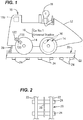
- one vehicle 10 out of a plurality of vehicles of a ride system, is shown with a body 12, wheels 14 and appropriate indicia 16 along with a guest 18 seated therein.
- the vehicle 10 is disposed on a path such as a track 20 which includes rails 22 that are supported by cross beams 24.
- a bus bar or energizing rail 26 provides electrical energy from an electrical generator (described below) to the vehicle 10 through means of an electrode 28.
- a disc brake 30 is shown mounted to a wheel 14.
- the ride control system 50 comprises a path or track processor 52 which is in circuit with the energizing rail 26 comprising a number of circuit connections (not numbered) and a plurality of vehicle control systems 100 each being located with a vehicle 10 ( Figure 1 ).
- the track processor 52 may communicate via wireless communications with each vehicle control system 100, rather than via the energizing rail 26.
- the track processor 52 may comprise a programmable logic controller and monitors track functions such as mode of the track machine, stopping and starting functions, and control of all track-switching elements via fail-safe signals.
- the track processor 52 and each vehicle control system 100 may communicate to ensure the mode of the track machine is safely controlled for the all vehicles mounted to the track. If there is disagreement of the mode of the track or if the vehicle senses itself out of range for position, velocity, or acceleration parameters or other fault conditions, the vehicle will communicate to the track processor and/or other vehicle processors to cause a stop or other reaction for each vehicle 10.
- the track processor may also be configured to determine and broadcast an ideal location of each vehicle to each vehicle on the path according to some predetermined plan such as every vehicle is spaced equally along the path. Each vehicle may then synchronize or vary its position along the path by increasing velocity or braking to correct its spacing from other vehicles.
- the track processor 52 may be connected in circuit with a bi-directional voting circuit 56 ( Figure 4 ) comprising a number of semiconductor gates arranged in a known manner, the function of which is described in more detail below and dual outputs 58 for bus bar control signals used to define the mode of the track machine, monitored by a plurality of vehicles.
- Each vehicle control system 100 comprises an output switch controller 64 for energizing a shunt relay 66 and an input 68 for analog and/or digital signals sent from the track processor 52.
- a load resistor (not shown) may also be employed to provide a known load for one vehicle to the track processor 52 so that the number of vehicles can be defined by the value of the analog input (not shown).
- the control system 100 comprises a processor 110, a memory 112, a timer 114, a distance/speed sensor 116 and a vehicle energizing and stopping system 118.
- the processor 110, memory 112, timer 114, distance/speed sensor 116 and a portion of the vehicle energizing and stopping system 118 may be located in a compartment 119 located in the vehicle 10.
- the processor 110 may be any suitable processor such as a programmable logic controller.
- the memory 112 may be any suitable type including but not limited to RAM, ROM, EPROM, and flash.
- the memory 112 may store a program for the processor 110 and store a look up table for a predicted range of locations given a duration that a vehicle 10 is traveling along the track 20.
- the timer 114 provides a timing function that may be used by the processor 110 to time an actual duration that the vehicle 10 is traveling along the track 20.
- the distance/speed sensor 116 may comprise a magnet 120 and a magnetic field or optical sensor 122 which together function in a known manner to provide electrical pulses to the processor 110 which correspond to a distance traveled by the wheel 14.
- other sensors such as a multi-turn encoder may be employed.
- the pulses may be counted or directly measured by the processor 110 to determine a distance and, therefrom, a location of the vehicle 10 along the track 20.
- the distance/speed sensor 116 may also comprise known pulse shaping circuitry.
- the processor 110 is configured, via any suitable means such as software or firmware, to receive an initial signal from a start indicator 124 that the vehicle 10 has started traveling along the track 20 and thereafter, to continuously, or at regular intervals, calculate an actual location for the vehicle along the track as described above.
- the processor 110 is further configured to look up a predicted range of locations for the vehicle 10 along the track 20 based, e.g., on the duration from the timer 114 and compare that with the actual location. Where the actual location falls outside of that range of predicted locations, the processor 110 sends a signal along line 126 to the energizing and stopping system 118 which, as described in more detail below, is configured to stop the vehicle 10 from any further progress along the track 20 along with the progress of any other vehicles traveling along the track. Further, the processor 110 may be configured to receive an ideal location from the track processor 52 and compare its location to the ideal location and either brake or not brake, as described below, to thereby increase vehicle velocity to compensate.
- the energizing and stopping system 118 comprises a processor 128 interconnected with a memory 130, a power source 132, the output switch controller 64 (see also Figure 7 ), a brake controller 136 and a vehicle track monitor 138.
- the processor 128 may be similar to the processor 110 described above in connection with Figure 3 , or, in one optional embodiment, instead of two separate processors 110 and 128, it will be appreciated that both may be combined together as one processor that performs functions described herein for both processors.
- the memory 130 may be similar to the memory 112 described above and may function to store a program for configuring the processor 128.
- the power source 132 may be any suitable power source such as a battery, generator or transformer.
- the power source 132 may omitted and/or transform power received via the electrode 28.
- the power source 132 may provide sufficient electrical energy for energizing both the output switch controller 64 and the brake controller 136 which may be mounted to the brake 30 ( Figure 1 ).
- the vehicle track monitor 138 may be any suitable device for monitoring energy output along the energizing rail 26 and, upon absence of the energy notifies processor 128.
- the vehicle track monitor may also comprise an electrical motor (not shown) for driving the vehicle 10.
- the vehicle track monitor 138 is connected via the electrode 28 to the energizing rail 26 and through wheels 14 to a rail 22.
- An electrical generator 30 is connected in circuit between the electronically controlled circuit breaker 56, connected to the energizing rail 26, and a rail 22.
- the shunt relay 66 (see also Figure 7 ) that is normally closed is in circuit between the electrode 28 and the wheel 14 and is operated remotely by the switch controller 64.
- the processor 128 may be configured, via, e.g., software or firmware, to respond to a command signal from the processor 110 to stop movement of the vehicle 10 by notifying the brake controller 136 to apply the brake 30.
- the processor 128 is further configured to notify the output switch controller 64 to close shunt relay 66 to short the generator 30 and alert the bi- directional voting circuit 56 so that other vehicles traveling on the track 20 will be notified that stopping is required via each vehicles' vehicle track monitor system 138.
- the processor 128 may also be configured to review the current speed and apply the brake 30 where necessary as described above to correct when an error in position on the track 20 is identified as described above.
- the processor 128 may then alert the bi-directional voting circuit 56 so that other vehicles traveling on the track 20 will be notified that stopping is required.
- a method of monitoring and controlling location of a plurality of vehicles movable along a path in accordance with another embodiment of the present invention is illustrated generally at 200 in Figure 5 .
- the method comprises locating at least a portion of a vehicle control system on each vehicle, and as shown at 212, mounting a vehicle sensor device to each vehicle.
- the method also includes storing a range of predicted locations along the path for a given durations that each vehicle is on the path as shown at 214 and, as shown at 216, using each vehicle sensor to determine an actual location of each vehicle while the vehicle is moving along the path.
- the method comprises comparing the actual location of each vehicle to the range of predicted locations for a number of given durations and, as shown at 220, stopping all vehicles where any actual location is outside the range of predicted locations.
- Technical effects of the herein described systems and methods include determining a location of a vehicle on a track. Other technical effects include determining whether the location is within a range of predicted locations.
Landscapes
- Engineering & Computer Science (AREA)
- Mechanical Engineering (AREA)
- Health & Medical Sciences (AREA)
- Biomedical Technology (AREA)
- General Health & Medical Sciences (AREA)
- Electric Propulsion And Braking For Vehicles (AREA)
- Train Traffic Observation, Control, And Security (AREA)
- Management, Administration, Business Operations System, And Electronic Commerce (AREA)
Claims (15)
- Fahrsteuersystem (50) zum Steuern einer Mehrzahl von Fahrzeugen (10) auf einer Bahn (20), wobei das Fahrsteuersystem Folgendes umfasst:einen Bahnprozessor (52);eine Sammelschiene (26) zum Leiten von elektrischen Signalen entlang der Bahn (20);einen Stromgenerator (30) für die Energieversorgung der Sammelschiene (26); undeinen elektronisch gesteuerten Leistungsschalter (56) in Schaltkreisverbindung mit dem Bahnprozessor (52) und dem Stromgenerator (30);wobei jedes Fahrzeug (10) aus der Mehrzahl von Fahrzeugen (10) Folgendes umfasst:einen Fahrzeugprozessor (128), der von dem mindestens einen Fahrzeug (10) getragen wird;ein Fahrzeug-Spurüberwachungssystem (138), das dazu angeordnet ist, die Energieabgabe entlang der Sammelschiene (26) zu überwachen und bei Fehlen von Energie den Fahrzeugprozessor (128) zu benachrichtigen, undein Nebenschlussrelais (66) in Schaltkreisverbindung mit dem mindestens einen Fahrzeugprozessor (128) und dem elektronisch gesteuerten Leistungsschalter (56);wobei die Sammelschiene (26) zwischen dem Bahnprozessor (52) und jedem Fahrzeugprozessor (128) in Schaltkreisverbindung ist; und jeder Fahrzeugprozessor (128) dazu konfiguriert ist, ein entsprechendes Nebenschlussrelais (66) bei einer vorgegebenen Bedingung des Fahrzeugs (10) zu schließen, wodurch der elektronisch gesteuerte Leistungsschalter (56) dazu aktiviert wird, die Sammelschiene (26) stromlos zu machen und damit alle anderen Fahrzeuge (10) aus der Mehrzahl von Fahrzeugen über deren jeweilige Fahrzeug-Spurüberwachungssysteme (138) zu benachrichtigen.
- System nach Anspruch 1, wobei die vorgegebene Bedingung des Fahrzeugs (10) ist, dass das Fahrzeug (10) nicht an einem vorherberechneten Standort entlang der Bahn (20) angeordnet ist und wobei der elektronisch gesteuerte Leistungsschalter (56) aktiviert wird, alle Fahrzeuge (10) anzuhalten.
- System nach Anspruch 2, wobei die elektrischen Signale über ein Netzwerk mittels analoger und/oder digitaler Signale übertragen werden.
- System nach Anspruch 1, wobei jedes Fahrzeug einen Belastungswiderstand umfasst, um dem Spurprozessor (52) eine bekannte Last für ein Fahrzeug (10) bereitzustellen, und der Spurprozessor dazu angeordnet ist, die Anzahl von Fahrzeugen auf der Spur durch den Wert der Gesamtlast zu bestimmen.
- System nach einem der vorstehenden Ansprüche, wobei jedes Fahrzeug (10) Folgendes umfasst:ein Fahrzeugsteuersystem (100), das an jedem Fahrzeug (10) angeordnet und dazu konfiguriert ist, einen tatsächlichen Standort von jedem speziellen Fahrzeug (10) zu bestimmen, während das Fahrzeug (10) sich entlang der Bahn (20) bewegt, und den tatsächlichen Standort mit einem Bereich von vorherberechneten Standorten zu vergleichen, und das Fahrzeugsteuersystem (100) weiterhin dazu konfiguriert ist, alle Fahrzeuge (10) auf der Bahn (20) anzuhalten, wo der tatsächliche Standort eines speziellen Fahrzeugs (10) sich außerhalb des Bereichs von vorherberechneten Standorten befindet.
- System nach Anspruch 5, wobei der Bahnprozessor (52) dazu konfiguriert ist, einen vorherberechneten Standort für jedes Fahrzeug (10) entlang der Bahn (20) jedem Fahrzeugsteuersystem (100) zu kommunizieren, und wobei das Fahrzeugsteuersystem (100) weiterhin dazu konfiguriert ist, eine Istgeschwindigkeit des Fahrzeugs (10) zu bestimmen, während das Fahrzeug (10) sich entlang der Bahn (20) bewegt, und die Istgeschwindigkeit des Fahrzeugs (10) mit einer maximalen Geschwindigkeit für einen speziellen Standort der Bahn (20) und des Fahrzeugs (10) zu vergleichen, wobei das Steuersystem (100) weiterhin dazu konfiguriert ist, die Geschwindigkeit des Fahrzeugs (10) zu vermindern oder zu erhöhen.
- System nach Anspruch 6, wobei das Fahrzeugsteuersystem (100) Folgendes umfasst:einen Abstandssensor (116) zum Erfassen eines Abstandes, in dem sich das Fahrzeug (10) entlang der Bahn (20) bewegt hat, um einen tatsächlichen Standort bereitzustellen;einen Timer (114) zum Bereitstellen der Zeitdauer, während der sich das Fahrzeug (10) auf der Bahn (20) befunden hat;einen Prozessor (110), wobei der Prozessor (110) dazu konfiguriert ist, den tatsächlichen Standort des Fahrzeugs (10) auf der Bahn (20) mit einem vorherberechneten Standortbereich zu vergleichen und ein Signal an den Bahnprozessor (52) auszugeben, alle Fahrzeuge (10) anzuhalten, wo der tatsächliche Standort nicht innerhalb des Bereichs von vorherberechneten Standorten liegt.
- System nach Anspruch 7, wobei:der Abstandssensor (116) weiterhin dazu konfiguriert ist, eine Istgeschwindigkeit zu bestimmen, mit der das Fahrzeug (10) sich entlang der Bahn (20) bewegt;das Speichergerät (112) weiterhin dazu konfiguriert ist, eine Nachschlagetabelle mit der maximalen Geschwindigkeit für jeden der Bereiche von Standorten entlang der Bahn (20) zu speichern;und der Prozessor (110) weiterhin dazu konfiguriert ist, die Istgeschwindigkeit des Fahrzeugs (10) mit der maximalen Geschwindigkeit für den Standortbereich entlang der Bahn basierend auf dem tatsächlichen Standort des Fahrzeugs (10) entlang der Bahn (20) zu vergleichen und ein Signal an den Bahnprozessor (52) auszugeben, um alle Fahrzeuge (10) anzuhalten, wenn der tatsächliche Standort nicht innerhalb des Bereichs von vorherberechneten Standorten liegt.
- System nach Anspruch 1, wobei die Sammelschiene (26) dazu angeordnet ist, jedes von einer Mehrzahl von Fahrzeugen (10) mit Energie für die Bewegung zu versorgen, wobei das Fahrzeugsteuersystem (100) ferner eine Bremse (30) zum Anhalten jedes Fahrzeugs (10) nach dem Öffnen des elektronisch gesteuerten Leistungsschalters (56) umfasst.
- System nach Anspruch 9, wobei jedes Fahrzeug (10) ein Vergnügungsfahrzeug und die Bahn (20) eine Spur (20) mit einem Schienenpaar (22) umfasst.
- System nach Anspruch 10, wobei jedes Fahrzeug (10) eine Mehrzahl von Rädern (14) umfasst und jeder Abstandssensor (116) einen in der Nähe des Rades (14) montierten Magnetfeldsensor (122) umfasst.
- System nach Anspruch 1, wobei das Fahrzeug-Spurüberwachungssystem (138) einen Elektromotor zum Antreiben des Fahrzeugs (10) umfasst.
- System nach Anspruch 1, wobei die Fahrzeug-Spurüberwachung mit der Sammelschiene (26) über eine Elektrode (28) und durch Räder (14) des Fahrzeugs (10) mit einer Schiene (22) der Bahn (20) verbunden ist.
- Verfahren zum Steuern einer Mehrzahl von Fahrzeugen (10) auf einer Bahn (20), wobei das Verfahren Folgendes umfasst:Bereitstellen eines Bahnprozessors (52);Führen von elektrischen Signalen entlang der Bahn (20) mittels einer Sammelschiene (26);Versorgen der Sammelschiene (26) mit Energie mittels eines Stromgenerators (30); undBereitstellen eines elektronisch gesteuerten Leistungsschalters (56) in Schaltkreisverbindung mit dem Bahnprozessor (52) und dem Stromgenerator (30);Bereitstellen jedes Fahrzeugs (10) aus der Mehrzahl von Fahrzeugen (10) mit Folgendem:einem Fahrzeugprozessor (128), der von dem mindestens einen Fahrzeug (10) getragen wird;einem Fahrzeug-Spurüberwachungssystem (138), das dazu angeordnet ist, die Energieabgabe entlang der Sammelschiene (26) zu überwachen und bei Fehlen von Energie den Fahrzeugprozessor (128) zu benachrichtigen, undeinem Nebenschlussrelais (66) in Schaltkreisverbindung mit dem mindestens einen Fahrzeugprozessor (128) und dem elektronisch gesteuerten Leistungsschalter (56);wobei das Verfahren weiterhin Folgendes umfasst: Bereitstellen der Sammelschiene (26) in Schaltkreisverbindung zwischen dem Bahnprozessor (52) und jedem Fahrzeugprozessor (128); Konfigurieren jedes Fahrzeugprozessors (128) dazu , ein entsprechendes Nebenschlussrelais (66) bei einer vorgegebenen Bedingung des Fahrzeugs (10) zu schließen; Aktivieren des elektronisch gesteuerten Leistungsschalters (56) dazu , die Sammelschiene (26) stromlos zu machen und damit alle anderen Fahrzeuge (10) über deren jeweilige Fahrzeug-Spurüberwachungssysteme (138) zu benachrichtigen.
- Verfahren von Anspruch 14, weiterhin umfassend das Kommunizieren von erwarteten Positionsdaten zwischen den Fahrzeugen (10) und dem Bahnprozessor (52).
Priority Applications (1)
| Application Number | Priority Date | Filing Date | Title |
|---|---|---|---|
| EP18168855.7A EP3470125B1 (de) | 2007-08-30 | 2008-06-12 | Virtueller omnimover |
Applications Claiming Priority (2)
| Application Number | Priority Date | Filing Date | Title |
|---|---|---|---|
| US11/847,612 US9014965B2 (en) | 2007-08-30 | 2007-08-30 | Virtual omnimover |
| PCT/US2008/066722 WO2009032382A2 (en) | 2007-08-30 | 2008-06-12 | Virtual omnimover |
Related Child Applications (1)
| Application Number | Title | Priority Date | Filing Date |
|---|---|---|---|
| EP18168855.7A Division EP3470125B1 (de) | 2007-08-30 | 2008-06-12 | Virtueller omnimover |
Publications (2)
| Publication Number | Publication Date |
|---|---|
| EP2185259A2 EP2185259A2 (de) | 2010-05-19 |
| EP2185259B1 true EP2185259B1 (de) | 2018-04-25 |
Family
ID=39942795
Family Applications (2)
| Application Number | Title | Priority Date | Filing Date |
|---|---|---|---|
| EP18168855.7A Active EP3470125B1 (de) | 2007-08-30 | 2008-06-12 | Virtueller omnimover |
| EP08770852.5A Active EP2185259B1 (de) | 2007-08-30 | 2008-06-12 | Virtueller omnimover |
Family Applications Before (1)
| Application Number | Title | Priority Date | Filing Date |
|---|---|---|---|
| EP18168855.7A Active EP3470125B1 (de) | 2007-08-30 | 2008-06-12 | Virtueller omnimover |
Country Status (8)
| Country | Link |
|---|---|
| US (3) | US9014965B2 (de) |
| EP (2) | EP3470125B1 (de) |
| JP (1) | JP5314023B2 (de) |
| KR (1) | KR101208268B1 (de) |
| CN (1) | CN101868285B (de) |
| ES (2) | ES2914713T3 (de) |
| SG (1) | SG183766A1 (de) |
| WO (1) | WO2009032382A2 (de) |
Families Citing this family (16)
| Publication number | Priority date | Publication date | Assignee | Title |
|---|---|---|---|---|
| US8660794B2 (en) * | 2007-07-13 | 2014-02-25 | Dash Navigation, Inc. | System and method for providing shared information about traveled road segments |
| US9308926B2 (en) * | 2008-12-29 | 2016-04-12 | Universal City Studios Llc | Position control system |
| DE102009032314A1 (de) * | 2009-07-09 | 2011-01-13 | Wabco Gmbh | Verfahren zur korrekten Durchführung von autonomen Notbremsungen bei einem Straßenfahrzeug |
| US9457282B2 (en) * | 2014-05-21 | 2016-10-04 | Universal City Studios Llc | Virtual attraction controller |
| US10086299B2 (en) * | 2014-08-15 | 2018-10-02 | Universal City Studios Llc | System and method for modular ride vehicles |
| KR102504687B1 (ko) * | 2015-03-06 | 2023-02-28 | 오셔니어링 인터내셔날, 인코포레이티드 | 탑승 차량 제어를 위한 버블 로직 |
| US10556511B2 (en) | 2015-05-04 | 2020-02-11 | Vekoma Rides Engineering B.V. | Amusement ride with speed trim system |
| US10099149B2 (en) | 2015-10-02 | 2018-10-16 | Universal City Studios Llc | Amusement park ride tunnel |
| US10279823B2 (en) * | 2016-08-08 | 2019-05-07 | General Electric Company | System for controlling or monitoring a vehicle system along a route |
| JP6443418B2 (ja) * | 2016-10-03 | 2018-12-26 | トヨタ自動車株式会社 | 車両運転支援装置 |
| CA3041326C (en) | 2016-10-27 | 2024-05-07 | Universal City Studios Llc | Systems and methods for ride control synchronization |
| EP3538233B1 (de) * | 2016-11-11 | 2020-09-09 | Antonio Zamperla S.p.A. | Spurloses fahrgeschäft |
| US11439921B2 (en) * | 2018-06-25 | 2022-09-13 | Universal City Studios Llc | Multi-dimensional bogie and track system |
| US11517828B2 (en) | 2019-06-19 | 2022-12-06 | Universal City Studios Llc | Choreographed ride systems and methods |
| KR102734388B1 (ko) * | 2022-08-19 | 2024-11-27 | 주식회사 에스티씨엔지니어링 | 궤도 장치를 구비한 화물 하차 자동화 머신 |
| AU2024216409A1 (en) * | 2023-08-30 | 2025-03-20 | Transportation Ip Holdings, Llc | System and method to determine a location of a designated position of a vehicle system |
Family Cites Families (16)
| Publication number | Priority date | Publication date | Assignee | Title |
|---|---|---|---|---|
| GB1604154A (en) * | 1978-05-30 | 1981-12-02 | Westinghouse Brake & Signal | Railway control systems |
| JPH03125664A (ja) * | 1989-10-06 | 1991-05-29 | Sumitomo Metal Ind Ltd | 車両自動運転装置 |
| US5403238A (en) * | 1993-08-19 | 1995-04-04 | The Walt Disney Company | Amusement park attraction |
| JPH07245814A (ja) * | 1994-03-03 | 1995-09-19 | Hitachi Ltd | 鉄道車両の自動運転制御装置 |
| US5595121A (en) * | 1994-04-15 | 1997-01-21 | The Walt Disney Company | Amusement ride and self-propelled vehicle therefor |
| US5995895A (en) * | 1997-07-15 | 1999-11-30 | Case Corporation | Control of vehicular systems in response to anticipated conditions predicted using predetermined geo-referenced maps |
| US6109568A (en) * | 1998-10-23 | 2000-08-29 | Innovative Transportation Systems International, Inc. | Control system and method for moving multiple automated vehicles along a monorail |
| US6170402B1 (en) * | 1999-04-21 | 2001-01-09 | Universal City Studios, Inc. | Roller coaster control system |
| CN2416940Y (zh) * | 2000-04-25 | 2001-01-31 | 黄培远 | 电驱动滑道车 |
| US6631873B2 (en) * | 2000-05-12 | 2003-10-14 | Glen T. Fisher | Protection device to prevent train incursions into a forbidden area |
| US6796908B2 (en) * | 2001-06-14 | 2004-09-28 | Creative Kingdoms, Llc | Interactive dark ride |
| DE50308942D1 (de) * | 2002-10-30 | 2008-02-14 | Duerr Systems Gmbh | Spurgeführtes transportsystem und verfahren zum steuern von fahrwagen eines spurgeführten transportsystems |
| AT500701A1 (de) * | 2004-03-24 | 2006-03-15 | Innova Patent Gmbh | Bahn mit durch schwerkraft angetriebenen fahrzeugen und verfahren zum steuern des betriebes dieser bahn |
| US7451029B2 (en) * | 2004-12-04 | 2008-11-11 | Cnh America Llc | Vehicle direction estimation using transmission control information |
| JP4744233B2 (ja) * | 2005-08-23 | 2011-08-10 | 泉陽興業株式会社 | 乗り物装置 |
| US8370006B2 (en) * | 2006-03-20 | 2013-02-05 | General Electric Company | Method and apparatus for optimizing a train trip using signal information |
-
2007
- 2007-08-30 US US11/847,612 patent/US9014965B2/en active Active
-
2008
- 2008-06-12 JP JP2010522984A patent/JP5314023B2/ja active Active
- 2008-06-12 EP EP18168855.7A patent/EP3470125B1/de active Active
- 2008-06-12 SG SG2012062816A patent/SG183766A1/en unknown
- 2008-06-12 ES ES18168855T patent/ES2914713T3/es active Active
- 2008-06-12 EP EP08770852.5A patent/EP2185259B1/de active Active
- 2008-06-12 ES ES08770852.5T patent/ES2673002T3/es active Active
- 2008-06-12 CN CN2008801046607A patent/CN101868285B/zh active Active
- 2008-06-12 KR KR1020107006964A patent/KR101208268B1/ko active Active
- 2008-06-12 WO PCT/US2008/066722 patent/WO2009032382A2/en not_active Ceased
-
2015
- 2015-04-02 US US14/677,737 patent/US9296400B2/en active Active
-
2016
- 2016-03-01 US US15/057,994 patent/US10183685B2/en active Active
Non-Patent Citations (1)
| Title |
|---|
| None * |
Also Published As
| Publication number | Publication date |
|---|---|
| ES2914713T3 (es) | 2022-06-15 |
| US10183685B2 (en) | 2019-01-22 |
| JP2010537879A (ja) | 2010-12-09 |
| EP3470125B1 (de) | 2022-03-16 |
| CN101868285A (zh) | 2010-10-20 |
| KR101208268B1 (ko) | 2012-12-04 |
| WO2009032382A3 (en) | 2009-07-30 |
| EP3470125A1 (de) | 2019-04-17 |
| WO2009032382A2 (en) | 2009-03-12 |
| US20090063036A1 (en) | 2009-03-05 |
| EP2185259A2 (de) | 2010-05-19 |
| US20160176421A1 (en) | 2016-06-23 |
| US20150210301A1 (en) | 2015-07-30 |
| KR20100063761A (ko) | 2010-06-11 |
| CN101868285B (zh) | 2012-12-26 |
| JP5314023B2 (ja) | 2013-10-16 |
| SG183766A1 (en) | 2012-09-27 |
| US9296400B2 (en) | 2016-03-29 |
| US9014965B2 (en) | 2015-04-21 |
| ES2673002T3 (es) | 2018-06-19 |
Similar Documents
| Publication | Publication Date | Title |
|---|---|---|
| US9296400B2 (en) | Virtual omnimover | |
| CA2748205C (en) | Position control system | |
| US9156482B2 (en) | Locator loop control system and method of using the same | |
| EP2614983A2 (de) | Zugsteuersystem | |
| JP2010228648A (ja) | 踏切制御装置 | |
| JP6765550B2 (ja) | 列車運転制御装置、運行管理装置、列車制御システム、および列車運転方法 | |
| HK40006865B (en) | Virtual omnimover | |
| HK40006865A (en) | Virtual omnimover | |
| JPH02109773A (ja) | 踏切制御装置 | |
| MXPA02003081A (es) | Instalacion y procedimiento para el ahorro de energia motriz en vehiculos del riel. | |
| KR101378357B1 (ko) | 궤도 차량의 교차 검지장치 | |
| KR200435598Y1 (ko) | 열차 정위치 정차 자동 제어시스템 | |
| KR100756186B1 (ko) | 열차 정위치 정차 자동 제어시스템 및 그 제어방법 | |
| RU2544285C1 (ru) | Устройство управления переездной сигнализацией | |
| JPH07298403A (ja) | 列車制御装置 | |
| RU191737U1 (ru) | Система управления движением электроподвижного состава | |
| KR100764007B1 (ko) | 전철보수차량의 경광등을 이용한 작업자 안전시스템 |
Legal Events
| Date | Code | Title | Description |
|---|---|---|---|
| PUAI | Public reference made under article 153(3) epc to a published international application that has entered the european phase |
Free format text: ORIGINAL CODE: 0009012 |
|
| 17P | Request for examination filed |
Effective date: 20100330 |
|
| AK | Designated contracting states |
Kind code of ref document: A2 Designated state(s): AT BE BG CH CY CZ DE DK EE ES FI FR GB GR HR HU IE IS IT LI LT LU LV MC MT NL NO PL PT RO SE SI SK TR |
|
| AX | Request for extension of the european patent |
Extension state: AL BA MK RS |
|
| RAP1 | Party data changed (applicant data changed or rights of an application transferred) |
Owner name: NBCUNIVERSAL MEDIA, LLC |
|
| DAX | Request for extension of the european patent (deleted) | ||
| 17Q | First examination report despatched |
Effective date: 20141114 |
|
| STAA | Information on the status of an ep patent application or granted ep patent |
Free format text: STATUS: EXAMINATION IS IN PROGRESS |
|
| GRAP | Despatch of communication of intention to grant a patent |
Free format text: ORIGINAL CODE: EPIDOSNIGR1 |
|
| STAA | Information on the status of an ep patent application or granted ep patent |
Free format text: STATUS: GRANT OF PATENT IS INTENDED |
|
| INTG | Intention to grant announced |
Effective date: 20170927 |
|
| RIN1 | Information on inventor provided before grant (corrected) |
Inventor name: KING, STEVEN, MORRIS Inventor name: LONG, HENRY, WILLIAM |
|
| GRAS | Grant fee paid |
Free format text: ORIGINAL CODE: EPIDOSNIGR3 |
|
| GRAJ | Information related to disapproval of communication of intention to grant by the applicant or resumption of examination proceedings by the epo deleted |
Free format text: ORIGINAL CODE: EPIDOSDIGR1 |
|
| GRAL | Information related to payment of fee for publishing/printing deleted |
Free format text: ORIGINAL CODE: EPIDOSDIGR3 |
|
| STAA | Information on the status of an ep patent application or granted ep patent |
Free format text: STATUS: EXAMINATION IS IN PROGRESS |
|
| GRAA | (expected) grant |
Free format text: ORIGINAL CODE: 0009210 |
|
| GRAR | Information related to intention to grant a patent recorded |
Free format text: ORIGINAL CODE: EPIDOSNIGR71 |
|
| STAA | Information on the status of an ep patent application or granted ep patent |
Free format text: STATUS: THE PATENT HAS BEEN GRANTED |
|
| INTC | Intention to grant announced (deleted) | ||
| AK | Designated contracting states |
Kind code of ref document: B1 Designated state(s): AT BE BG CH CY CZ DE DK EE ES FI FR GB GR HR HU IE IS IT LI LT LU LV MC MT NL NO PL PT RO SE SI SK TR |
|
| INTG | Intention to grant announced |
Effective date: 20180319 |
|
| REG | Reference to a national code |
Ref country code: GB Ref legal event code: FG4D |
|
| REG | Reference to a national code |
Ref country code: CH Ref legal event code: EP |
|
| REG | Reference to a national code |
Ref country code: AT Ref legal event code: REF Ref document number: 992269 Country of ref document: AT Kind code of ref document: T Effective date: 20180515 |
|
| REG | Reference to a national code |
Ref country code: IE Ref legal event code: FG4D |
|
| REG | Reference to a national code |
Ref country code: DE Ref legal event code: R096 Ref document number: 602008055004 Country of ref document: DE |
|
| REG | Reference to a national code |
Ref country code: ES Ref legal event code: FG2A Ref document number: 2673002 Country of ref document: ES Kind code of ref document: T3 Effective date: 20180619 |
|
| REG | Reference to a national code |
Ref country code: FR Ref legal event code: PLFP Year of fee payment: 11 |
|
| REG | Reference to a national code |
Ref country code: CH Ref legal event code: NV Representative=s name: MICHELI AND CIE SA, CH |
|
| REG | Reference to a national code |
Ref country code: NL Ref legal event code: MP Effective date: 20180425 |
|
| REG | Reference to a national code |
Ref country code: LT Ref legal event code: MG4D |
|
| PG25 | Lapsed in a contracting state [announced via postgrant information from national office to epo] |
Ref country code: NL Free format text: LAPSE BECAUSE OF FAILURE TO SUBMIT A TRANSLATION OF THE DESCRIPTION OR TO PAY THE FEE WITHIN THE PRESCRIBED TIME-LIMIT Effective date: 20180425 |
|
| PG25 | Lapsed in a contracting state [announced via postgrant information from national office to epo] |
Ref country code: LT Free format text: LAPSE BECAUSE OF FAILURE TO SUBMIT A TRANSLATION OF THE DESCRIPTION OR TO PAY THE FEE WITHIN THE PRESCRIBED TIME-LIMIT Effective date: 20180425 Ref country code: PL Free format text: LAPSE BECAUSE OF FAILURE TO SUBMIT A TRANSLATION OF THE DESCRIPTION OR TO PAY THE FEE WITHIN THE PRESCRIBED TIME-LIMIT Effective date: 20180425 Ref country code: SE Free format text: LAPSE BECAUSE OF FAILURE TO SUBMIT A TRANSLATION OF THE DESCRIPTION OR TO PAY THE FEE WITHIN THE PRESCRIBED TIME-LIMIT Effective date: 20180425 Ref country code: FI Free format text: LAPSE BECAUSE OF FAILURE TO SUBMIT A TRANSLATION OF THE DESCRIPTION OR TO PAY THE FEE WITHIN THE PRESCRIBED TIME-LIMIT Effective date: 20180425 Ref country code: BG Free format text: LAPSE BECAUSE OF FAILURE TO SUBMIT A TRANSLATION OF THE DESCRIPTION OR TO PAY THE FEE WITHIN THE PRESCRIBED TIME-LIMIT Effective date: 20180725 Ref country code: NO Free format text: LAPSE BECAUSE OF FAILURE TO SUBMIT A TRANSLATION OF THE DESCRIPTION OR TO PAY THE FEE WITHIN THE PRESCRIBED TIME-LIMIT Effective date: 20180725 |
|
| PG25 | Lapsed in a contracting state [announced via postgrant information from national office to epo] |
Ref country code: HR Free format text: LAPSE BECAUSE OF FAILURE TO SUBMIT A TRANSLATION OF THE DESCRIPTION OR TO PAY THE FEE WITHIN THE PRESCRIBED TIME-LIMIT Effective date: 20180425 Ref country code: GR Free format text: LAPSE BECAUSE OF FAILURE TO SUBMIT A TRANSLATION OF THE DESCRIPTION OR TO PAY THE FEE WITHIN THE PRESCRIBED TIME-LIMIT Effective date: 20180726 Ref country code: LV Free format text: LAPSE BECAUSE OF FAILURE TO SUBMIT A TRANSLATION OF THE DESCRIPTION OR TO PAY THE FEE WITHIN THE PRESCRIBED TIME-LIMIT Effective date: 20180425 |
|
| PG25 | Lapsed in a contracting state [announced via postgrant information from national office to epo] |
Ref country code: PT Free format text: LAPSE BECAUSE OF FAILURE TO SUBMIT A TRANSLATION OF THE DESCRIPTION OR TO PAY THE FEE WITHIN THE PRESCRIBED TIME-LIMIT Effective date: 20180827 |
|
| REG | Reference to a national code |
Ref country code: DE Ref legal event code: R097 Ref document number: 602008055004 Country of ref document: DE |
|
| PG25 | Lapsed in a contracting state [announced via postgrant information from national office to epo] |
Ref country code: SK Free format text: LAPSE BECAUSE OF FAILURE TO SUBMIT A TRANSLATION OF THE DESCRIPTION OR TO PAY THE FEE WITHIN THE PRESCRIBED TIME-LIMIT Effective date: 20180425 Ref country code: DK Free format text: LAPSE BECAUSE OF FAILURE TO SUBMIT A TRANSLATION OF THE DESCRIPTION OR TO PAY THE FEE WITHIN THE PRESCRIBED TIME-LIMIT Effective date: 20180425 Ref country code: CZ Free format text: LAPSE BECAUSE OF FAILURE TO SUBMIT A TRANSLATION OF THE DESCRIPTION OR TO PAY THE FEE WITHIN THE PRESCRIBED TIME-LIMIT Effective date: 20180425 Ref country code: EE Free format text: LAPSE BECAUSE OF FAILURE TO SUBMIT A TRANSLATION OF THE DESCRIPTION OR TO PAY THE FEE WITHIN THE PRESCRIBED TIME-LIMIT Effective date: 20180425 Ref country code: RO Free format text: LAPSE BECAUSE OF FAILURE TO SUBMIT A TRANSLATION OF THE DESCRIPTION OR TO PAY THE FEE WITHIN THE PRESCRIBED TIME-LIMIT Effective date: 20180425 |
|
| PLBE | No opposition filed within time limit |
Free format text: ORIGINAL CODE: 0009261 |
|
| STAA | Information on the status of an ep patent application or granted ep patent |
Free format text: STATUS: NO OPPOSITION FILED WITHIN TIME LIMIT |
|
| REG | Reference to a national code |
Ref country code: BE Ref legal event code: MM Effective date: 20180630 |
|
| REG | Reference to a national code |
Ref country code: IE Ref legal event code: MM4A |
|
| PG25 | Lapsed in a contracting state [announced via postgrant information from national office to epo] |
Ref country code: LU Free format text: LAPSE BECAUSE OF NON-PAYMENT OF DUE FEES Effective date: 20180612 Ref country code: MC Free format text: LAPSE BECAUSE OF FAILURE TO SUBMIT A TRANSLATION OF THE DESCRIPTION OR TO PAY THE FEE WITHIN THE PRESCRIBED TIME-LIMIT Effective date: 20180425 |
|
| 26N | No opposition filed |
Effective date: 20190128 |
|
| PG25 | Lapsed in a contracting state [announced via postgrant information from national office to epo] |
Ref country code: IE Free format text: LAPSE BECAUSE OF NON-PAYMENT OF DUE FEES Effective date: 20180612 |
|
| PG25 | Lapsed in a contracting state [announced via postgrant information from national office to epo] |
Ref country code: BE Free format text: LAPSE BECAUSE OF NON-PAYMENT OF DUE FEES Effective date: 20180630 Ref country code: SI Free format text: LAPSE BECAUSE OF FAILURE TO SUBMIT A TRANSLATION OF THE DESCRIPTION OR TO PAY THE FEE WITHIN THE PRESCRIBED TIME-LIMIT Effective date: 20180425 |
|
| PG25 | Lapsed in a contracting state [announced via postgrant information from national office to epo] |
Ref country code: MT Free format text: LAPSE BECAUSE OF NON-PAYMENT OF DUE FEES Effective date: 20180612 |
|
| PG25 | Lapsed in a contracting state [announced via postgrant information from national office to epo] |
Ref country code: TR Free format text: LAPSE BECAUSE OF FAILURE TO SUBMIT A TRANSLATION OF THE DESCRIPTION OR TO PAY THE FEE WITHIN THE PRESCRIBED TIME-LIMIT Effective date: 20180425 |
|
| PG25 | Lapsed in a contracting state [announced via postgrant information from national office to epo] |
Ref country code: HU Free format text: LAPSE BECAUSE OF FAILURE TO SUBMIT A TRANSLATION OF THE DESCRIPTION OR TO PAY THE FEE WITHIN THE PRESCRIBED TIME-LIMIT; INVALID AB INITIO Effective date: 20080612 |
|
| PG25 | Lapsed in a contracting state [announced via postgrant information from national office to epo] |
Ref country code: CY Free format text: LAPSE BECAUSE OF FAILURE TO SUBMIT A TRANSLATION OF THE DESCRIPTION OR TO PAY THE FEE WITHIN THE PRESCRIBED TIME-LIMIT Effective date: 20180425 |
|
| PG25 | Lapsed in a contracting state [announced via postgrant information from national office to epo] |
Ref country code: IS Free format text: LAPSE BECAUSE OF FAILURE TO SUBMIT A TRANSLATION OF THE DESCRIPTION OR TO PAY THE FEE WITHIN THE PRESCRIBED TIME-LIMIT Effective date: 20180825 |
|
| REG | Reference to a national code |
Ref country code: AT Ref legal event code: UEP Ref document number: 992269 Country of ref document: AT Kind code of ref document: T Effective date: 20180425 |
|
| P01 | Opt-out of the competence of the unified patent court (upc) registered |
Effective date: 20230522 |
|
| PGFP | Annual fee paid to national office [announced via postgrant information from national office to epo] |
Ref country code: DE Payment date: 20250627 Year of fee payment: 18 |
|
| PGFP | Annual fee paid to national office [announced via postgrant information from national office to epo] |
Ref country code: GB Payment date: 20250627 Year of fee payment: 18 |
|
| PGFP | Annual fee paid to national office [announced via postgrant information from national office to epo] |
Ref country code: FR Payment date: 20250625 Year of fee payment: 18 |
|
| PGFP | Annual fee paid to national office [announced via postgrant information from national office to epo] |
Ref country code: AT Payment date: 20250521 Year of fee payment: 18 |
|
| PGFP | Annual fee paid to national office [announced via postgrant information from national office to epo] |
Ref country code: ES Payment date: 20250701 Year of fee payment: 18 |
|
| PGFP | Annual fee paid to national office [announced via postgrant information from national office to epo] |
Ref country code: IT Payment date: 20250619 Year of fee payment: 18 |
|
| PGFP | Annual fee paid to national office [announced via postgrant information from national office to epo] |
Ref country code: CH Payment date: 20250701 Year of fee payment: 18 |