EP2185308B1 - Verfahren zum unterteilen und inkohärenten summieren eines kohärenten strahls - Google Patents
Verfahren zum unterteilen und inkohärenten summieren eines kohärenten strahls Download PDFInfo
- Publication number
- EP2185308B1 EP2185308B1 EP08771473.9A EP08771473A EP2185308B1 EP 2185308 B1 EP2185308 B1 EP 2185308B1 EP 08771473 A EP08771473 A EP 08771473A EP 2185308 B1 EP2185308 B1 EP 2185308B1
- Authority
- EP
- European Patent Office
- Prior art keywords
- axis
- beam splitters
- splitters
- optical
- light
- Prior art date
- Legal status (The legal status is an assumption and is not a legal conclusion. Google has not performed a legal analysis and makes no representation as to the accuracy of the status listed.)
- Active
Links
Images




Classifications
-
- B—PERFORMING OPERATIONS; TRANSPORTING
- B23—MACHINE TOOLS; METAL-WORKING NOT OTHERWISE PROVIDED FOR
- B23K—SOLDERING OR UNSOLDERING; WELDING; CLADDING OR PLATING BY SOLDERING OR WELDING; CUTTING BY APPLYING HEAT LOCALLY, e.g. FLAME CUTTING; WORKING BY LASER BEAM
- B23K26/00—Working by laser beam, e.g. welding, cutting or boring
- B23K26/02—Positioning or observing the workpiece, e.g. with respect to the point of impact; Aligning, aiming or focusing the laser beam
- B23K26/06—Shaping the laser beam, e.g. by masks or multi-focusing
- B23K26/0604—Shaping the laser beam, e.g. by masks or multi-focusing by a combination of beams
-
- G—PHYSICS
- G02—OPTICS
- G02B—OPTICAL ELEMENTS, SYSTEMS OR APPARATUS
- G02B27/00—Optical systems or apparatus not provided for by any of the groups G02B1/00 - G02B26/00, G02B30/00
- G02B27/28—Optical systems or apparatus not provided for by any of the groups G02B1/00 - G02B26/00, G02B30/00 for polarising
- G02B27/283—Optical systems or apparatus not provided for by any of the groups G02B1/00 - G02B26/00, G02B30/00 for polarising used for beam splitting or combining
-
- B—PERFORMING OPERATIONS; TRANSPORTING
- B23—MACHINE TOOLS; METAL-WORKING NOT OTHERWISE PROVIDED FOR
- B23K—SOLDERING OR UNSOLDERING; WELDING; CLADDING OR PLATING BY SOLDERING OR WELDING; CUTTING BY APPLYING HEAT LOCALLY, e.g. FLAME CUTTING; WORKING BY LASER BEAM
- B23K26/00—Working by laser beam, e.g. welding, cutting or boring
- B23K26/02—Positioning or observing the workpiece, e.g. with respect to the point of impact; Aligning, aiming or focusing the laser beam
- B23K26/06—Shaping the laser beam, e.g. by masks or multi-focusing
- B23K26/0604—Shaping the laser beam, e.g. by masks or multi-focusing by a combination of beams
- B23K26/0613—Shaping the laser beam, e.g. by masks or multi-focusing by a combination of beams having a common axis
-
- B—PERFORMING OPERATIONS; TRANSPORTING
- B23—MACHINE TOOLS; METAL-WORKING NOT OTHERWISE PROVIDED FOR
- B23K—SOLDERING OR UNSOLDERING; WELDING; CLADDING OR PLATING BY SOLDERING OR WELDING; CUTTING BY APPLYING HEAT LOCALLY, e.g. FLAME CUTTING; WORKING BY LASER BEAM
- B23K26/00—Working by laser beam, e.g. welding, cutting or boring
- B23K26/02—Positioning or observing the workpiece, e.g. with respect to the point of impact; Aligning, aiming or focusing the laser beam
- B23K26/06—Shaping the laser beam, e.g. by masks or multi-focusing
- B23K26/062—Shaping the laser beam, e.g. by masks or multi-focusing by direct control of the laser beam
- B23K26/0622—Shaping the laser beam, e.g. by masks or multi-focusing by direct control of the laser beam by shaping pulses
-
- B—PERFORMING OPERATIONS; TRANSPORTING
- B23—MACHINE TOOLS; METAL-WORKING NOT OTHERWISE PROVIDED FOR
- B23K—SOLDERING OR UNSOLDERING; WELDING; CLADDING OR PLATING BY SOLDERING OR WELDING; CUTTING BY APPLYING HEAT LOCALLY, e.g. FLAME CUTTING; WORKING BY LASER BEAM
- B23K26/00—Working by laser beam, e.g. welding, cutting or boring
- B23K26/02—Positioning or observing the workpiece, e.g. with respect to the point of impact; Aligning, aiming or focusing the laser beam
- B23K26/06—Shaping the laser beam, e.g. by masks or multi-focusing
- B23K26/067—Dividing the beam into multiple beams, e.g. multi-focusing
-
- G—PHYSICS
- G02—OPTICS
- G02B—OPTICAL ELEMENTS, SYSTEMS OR APPARATUS
- G02B27/00—Optical systems or apparatus not provided for by any of the groups G02B1/00 - G02B26/00, G02B30/00
- G02B27/10—Beam splitting or combining systems
-
- G—PHYSICS
- G02—OPTICS
- G02B—OPTICAL ELEMENTS, SYSTEMS OR APPARATUS
- G02B27/00—Optical systems or apparatus not provided for by any of the groups G02B1/00 - G02B26/00, G02B30/00
- G02B27/10—Beam splitting or combining systems
- G02B27/14—Beam splitting or combining systems operating by reflection only
- G02B27/144—Beam splitting or combining systems operating by reflection only using partially transparent surfaces without spectral selectivity
-
- G—PHYSICS
- G02—OPTICS
- G02B—OPTICAL ELEMENTS, SYSTEMS OR APPARATUS
- G02B27/00—Optical systems or apparatus not provided for by any of the groups G02B1/00 - G02B26/00, G02B30/00
- G02B27/10—Beam splitting or combining systems
- G02B27/14—Beam splitting or combining systems operating by reflection only
- G02B27/145—Beam splitting or combining systems operating by reflection only having sequential partially reflecting surfaces
-
- G—PHYSICS
- G02—OPTICS
- G02B—OPTICAL ELEMENTS, SYSTEMS OR APPARATUS
- G02B27/00—Optical systems or apparatus not provided for by any of the groups G02B1/00 - G02B26/00, G02B30/00
- G02B27/48—Laser speckle optics
-
- H—ELECTRICITY
- H10—SEMICONDUCTOR DEVICES; ELECTRIC SOLID-STATE DEVICES NOT OTHERWISE PROVIDED FOR
- H10P—GENERIC PROCESSES OR APPARATUS FOR THE MANUFACTURE OR TREATMENT OF DEVICES COVERED BY CLASS H10
- H10P72/00—Handling or holding of wafers, substrates or devices during manufacture or treatment thereof
- H10P72/04—Apparatus for manufacture or treatment
- H10P72/0431—Apparatus for thermal treatment
- H10P72/0436—Apparatus for thermal treatment mainly by radiation
-
- H—ELECTRICITY
- H01—ELECTRIC ELEMENTS
- H01S—DEVICES USING THE PROCESS OF LIGHT AMPLIFICATION BY STIMULATED EMISSION OF RADIATION [LASER] TO AMPLIFY OR GENERATE LIGHT; DEVICES USING STIMULATED EMISSION OF ELECTROMAGNETIC RADIATION IN WAVE RANGES OTHER THAN OPTICAL
- H01S3/00—Lasers, i.e. devices using stimulated emission of electromagnetic radiation in the infrared, visible or ultraviolet wave range
- H01S3/005—Optical devices external to the laser cavity, specially adapted for lasers, e.g. for homogenisation of the beam or for manipulating laser pulses, e.g. pulse shaping
-
- H—ELECTRICITY
- H10—SEMICONDUCTOR DEVICES; ELECTRIC SOLID-STATE DEVICES NOT OTHERWISE PROVIDED FOR
- H10P—GENERIC PROCESSES OR APPARATUS FOR THE MANUFACTURE OR TREATMENT OF DEVICES COVERED BY CLASS H10
- H10P34/00—Irradiation with electromagnetic or particle radiation of wafers, substrates or parts of devices
- H10P34/40—Irradiation with electromagnetic or particle radiation of wafers, substrates or parts of devices with high-energy radiation
- H10P34/42—Irradiation with electromagnetic or particle radiation of wafers, substrates or parts of devices with high-energy radiation with electromagnetic radiation, e.g. laser annealing
Definitions
- the light source 102 may be optically coupled to a decorrelator 104 for producing incoherent light in an effort to uniformly illuminate a target 106, such as a substrate undergoing semiconductor processing (e . g ., pulsed laser annealing) or two components being welded together.
- a target 106 such as a substrate undergoing semiconductor processing (e . g ., pulsed laser annealing) or two components being welded together.
- Optical coupling between the light source 102 and the decorrelator 104 and between the decorrelator 104 and the target 106 may occur via simple linear alignment of the devices, optical steering devices (e.g., mirrors, lenses, and beam splitters), optical fibers, and/or other optical waveguides depending on the application.
- optional optical conditioning devices e .
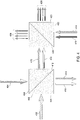
- the off-axis component light beams such as reflected component beam 214 and off-axis component light beams 414, 416, 428 in FIG. 4 , from one beam splitter may be optically steered and redirected to a subsequent beam splitter in step 308 by any optical steering device suitable for reflecting or redirecting light without significant optical loss, such as a mirror, a retroreflector, or an optical fiber.
- a retroreflector as used herein may be generally defined as a device that reflects light along a path parallel to an incident light beam regardless of the angle of incidence.
- the reflected component beam 214 from the first beam splitter 201 may be redirected by a primary retroreflector 216 to a secondary retroreflector 218.
- the secondary retroreflector 218 may redirect the reflected component beam 214 to the second beam splitter 202 for additional optical splitting.
- the maximum delay length between the primary retroreflectors 216 and secondary retroreflectors 218 is only 2 l in the simple example described herein
- the maximum delay length between the retroreflectors 501-504 in embodiments with the reduced number of optical steering devices is always twice as much ( i . e ., 41). Therefore, embodiments of the invention with the reduced number of optical steering devices as shown in FIG. 5 may suggest twice the amount of lateral spacing in the decorrelator 104 as embodiments with two optical steering devices between each beam splitter as shown in FIG. 2 .
- Each of these component light beams 212, 214 may be split into two additional component beams by the second beam splitter 202 such that the two on-axis component light beams transmitted through the second beam splitter 202 may have a zero delay and a 1 d delay length and the two-off axis component light beams reaching the third beam splitter 203 may have a 1 d delay length and a 2 d delay length.
- two of the four component light beams generated by the second beam splitter 202, the primary retroreflector 216, and the secondary retroreflector 218 have a 1 d delay length
- the other two component light beams have a zero delay and a 2 d delay length as depicted in the second row of the chart 250.
- This process may propagate down the remaining beam splitters 203-205 with each component light beam being split into two components that have zero delay added when transmitted as an on-axis component light beam and a 1 d delay added when transmitted as an off-axis component light beam.
- the generated component light beams may consist of a component light beam that was not delayed ( i .
- the separation in time due to optical travel through the off-axis optical paths including the optical steering devices should be on the order of a coherence length or more.
- the coherence length may be generally defined as the propagation distance from a coherent light source to a point where the light wave maintains a specified degree of coherence.
- Spatial decorrelation may be accomplished by an imperfect overlay of the component light beams.
- the beam splitters 201-205 and optical steering devices e . g ., the retroreflectors 216, 218, may not be perfectly aligned in an effort to cause displacements, deviations in transmission angles of the component light beams, or both.
- the separation in space should be sufficient to displace the speckle pattern by at least a speckle dot width at the image plane.
- D the diameter of the laser beam at its narrowest spot
- ⁇ 0 the vacuum wavelength of the light
- n the refractive index of the medium
- NA the numerical aperture
- the on-axis component light beams from the last beam splitter 205 may be transmitted to the beam combiner 222, while the off-axis component light beams from the last beam splitter 205 may be redirected to the beam combiner 222 using any suitable optical steering device or combination of devices, such as a retroreflector, a combination of mirrors, and an optical fiber.
- a retroreflector a combination of mirrors
- an optical fiber such as a retroreflector, a combination of mirrors, and an optical fiber.
- FIG. 2 FIG. 5
- the off-axis component beams from the last beam splitter 205 are redirected to the beam combiner 222 using a retroreflector 224 (505) and two mirrors 226, 228.
- the beam combiner 222 may comprise a polarization rotator or a half-wave plate 230 and a polarizing cube beam splitter 232 aligned with the optical axis A-A of the plurality of beam splitters 201-205.
- the half-wave plate 230 may be coupled directly to the polarizing beam splitter 232.
- the half-wave plate 230 may be positioned before the polarizing beam splitter 232 so that the polarization of the on-axis component light beams may be rotated 90°.
- the polarizing beam splitter 232 may adjust the polarization of the energy in the on-axis and off-axis component light beams received from the last beam splitter 205 or from the mirrors 226, 228, respectively, so that the composite beam may be directed in a desired direction.
- the benefit of incoherent summing may increase as the square root of the number of beams being summed ( ⁇ 2 N or 2 N/2 ).
- This improvement may be seen in high quality light sources, such as lasers with a small beam parameter product (BPP), the product of a laser beam's divergence angle (half-angle) and the radius of the beam at its narrowest point (beam waist).
- BPP beam parameter product
- M 2 The ratio of the BPP of an actual beam to that of an ideal Gaussian beam (having the lowest possible BPP of ⁇ / ⁇ ) at the same wavelength.
- the decorrelator 104 may employ ten alternating beam splitters 601-610.
- the first, seventh, and ninth beam splitters 601, 607, 609 may be cube beam splitters, while the remaining beam splitters 602-606, 608, 610 may be plate beam splitters.
- the ninth beam splitter 609 may be have a splitting ratio of 30:70, while the remaining beam splitters 601-608, 610 may possess a splitting ratio of 50:50.
- some embodiments may utilize different lateral spacing between each adjacent pair of beam splitters and the corresponding optical steering device.
- the temporal decorrelation may be further increased.
- the time delays of the component light beams from the last beam splitter may be less matched ( i . e ., more distributed), thereby leading to more uniform illumination in the incoherent light beam 220.
- some embodiments may employ a certain layout topology of optical steering devices between a pair of adjacent beam splitters (e . g ., a single off-axis retroreflector between adjacent beam splitters with a certain lateral spacing) and a different layout topology between another pair of adjacent beam splitters (e . g ., two or more optical steering devices between the pair of beam splitters most likely with a different lateral spacing) within the same decorrelator 104.
- a certain layout topology of optical steering devices between a pair of adjacent beam splitters e . g ., a single off-axis retroreflector between adjacent beam splitters with a certain lateral spacing
- another pair of adjacent beam splitters e . g ., two or more optical steering devices between the pair of beam splitters most likely with a different lateral spacing
- characteristics of the decorrelator 104 such as the number of beam splitters, the number of optical steering devices, the topology of the layout, and the dimensions of the layout (e . g ., the on-axis spacing between adjacent beam splitters, the lateral spacing between a beam splitter and one or more off-axis optical steering devices, and the spacing between the last beam splitter and the beam combiner)-may be selected and altered in an effort to adjust the amount of pulse stretching and to achieve a desired pulse profile when the incident light beam 210 is a coherent light pulse.
Landscapes
- Physics & Mathematics (AREA)
- Optics & Photonics (AREA)
- Engineering & Computer Science (AREA)
- General Physics & Mathematics (AREA)
- Plasma & Fusion (AREA)
- Mechanical Engineering (AREA)
- Spectroscopy & Molecular Physics (AREA)
- Laser Beam Processing (AREA)
- Lasers (AREA)
- Health & Medical Sciences (AREA)
- Toxicology (AREA)
Claims (15)
- Verfahren zum Dekorrelieren eines kohärenten Lichtstrahls, umfassend:Bereitstellen einer Vielzahl von Strahlteilern (201-205), die entlang einer optischen Achse (A-A) ausgerichtet sind;Empfangen des kohärenten Lichtstrahls mit einem ersten Strahlteiler (201) in der Vielzahl selbiger;für wenigstens manche der Strahlteiler, Unterteilen jedes einfallenden Lichtstrahls in einen auf der Achse liegenden Komponentenstrahl, der sich im Wesentlichen entlang der optischen Achse bewegt, und einen außerhalb der Achse liegenden Komponentenstrahl, der sich im Wesentlichen senkrecht zur optischen Achse bewegt;gekennzeichnet durch die folgenden Schritte:Kombinieren von auf der Achse und außerhalb der Achse liegenden Komponentenstrahlen, die von einem letzten Strahlteiler (205) in der Vielzahl selbiger in einem Strahlkombinierer (222) empfangen werden, der mit der optischen Achse der Strahlteiler ausgerichtet ist, um einen inkohärenten Lichtstrahl zu bilden; undoptisches Lenken jedes der außerhalb der Achse liegenden Komponentenstrahlen zu einem nachfolgenden Strahlteiler in der Vielzahl von Strahlteilern oder zum Strahlkombinierer.
- Verfahren nach Anspruch 1, wobei das Bereitstellen der Vielzahl von Strahlteilern das Bereitstellen von N Strahlteilern umfasst, die entlang der optischen Achse ausgerichtet sind, und das Kombinieren der auf der Achse und außerhalb der Achse liegenden Komponentenstrahlen das Kombinieren von 2N auf der Achse und außerhalb der Achse liegenden Komponentenstrahlen vom letzten Strahlteiler umfasst.
- Verfahren nach Anspruch 1, wobei der kohärente Lichtstrahl ein kohärenter Lichtimpuls ist und der inkohärente Lichtstrahl ein inkohärenter Lichtimpuls ist, dessen Impulsbreite länger ist als die des kohärenten Lichtimpulses.
- Verfahren nach Anspruch 1, wobei das optische Lenken der außerhalb der Achse liegenden Komponentenstrahlen zum nachfolgenden Strahlteiler oder zum Strahlkombinierer das Verwenden eines Retroreflektors, eines Spiegels, einer optischen Faser oder einer Kombination davon umfasst.
- Verfahren nach Anspruch 1, wobei das Kombinieren der auf der Achse liegenden und der außerhalb der Achse liegenden Komponentenstrahlen die Verwendung eines polarisierenden Strahlteilers (232) und einer Halbwellenplatte (230) als Strahlkombinierer umfasst.
- Verfahren zum Dekorrelieren eines kohärenten Lichtstrahls, umfassend:Bereitstellen von N Strahlteilern (201-205);gekennzeichnet durch die folgenden Schritte:Unterteilen des kohärenten Lichtstrahls in 2N-Komponentenstrahlen unter Verwendung von N Strahlteilern; undKombinieren der 2N-Komponentenstrahlen durch einen Strahlkombinierer (222), der auf die optische Achse der Strahlteiler ausgerichtet ist, um einen inkohärenten Lichtstrahl zu bilden.
- Verfahren nach Anspruch 6, wobei der kohärente Lichtstrahl ein kohärenter Lichtimpuls ist und der inkohärente Lichtstrahl ein inkohärenter Lichtimpuls ist, dessen Impulsbreite länger ist als die des kohärenten Lichtimpulses.
- Vorrichtung zum Dekorrelieren von kohärentem Licht, umfassend:eine Vielzahl von Strahlteilern (201-205), die entlang einer optischen Achse ausgerichtet sind, wobei wenigstens manche der Strahlteiler konfiguriert sind, um einen einfallenden Lichtstrahl in einen auf der Achse liegenden Komponentenstrahl, der sich im Wesentlichen entlang der optischen Achse bewegt, und einen außerhalb der Achse liegenden Komponentenstrahl, der sich im Wesentlichen senkrecht zur optischen Achse bewegt, zu teilen, wobei ein erster Strahlteiler (201) in der Vielzahl selbiger so konfiguriert ist, dass er das kohärente Licht empfängt;wobei die Vorrichtung dadurch gekennzeichnet ist, dass ein Strahlkombinierer (222) auf die optische Achse der Strahlteiler ausgerichtet und zum Kombinieren von auf der Achse und außerhalb der Achse liegenden Komponentenstrahlen, die von einem letzten Strahlteiler (205) in der Vielzahl selbiger empfangen werden, konfiguriert ist, um inkohärentes Licht zu bilden; undeine Vielzahl von optischen Lenkvorrichtungen konfiguriert ist, um außerhalb der Achse liegende Komponentenstrahlen auf einen nachfolgenden Strahlteiler in der Vielzahl von Strahlteilern oder auf den Strahlkombinierer zu lenken.
- Vorrichtung nach Anspruch 8, wobei das kohärente Licht ein kohärenter Lichtimpuls ist und das inkohärente Licht ein inkohärenter Lichtimpuls ist, der eine längere Impulsbreite als der kohärente Lichtimpuls aufweist.
- Vorrichtung nach Anspruch 8, wobei N die Anzahl der Strahlteiler in der Vielzahl selbiger ist und der Strahlkombinierer so konfiguriert ist, dass er 2N auf der Achse und außerhalb der Achse liegende Komponentenstrahlen vom letzten Strahlteiler empfängt.
- Vorrichtung nach Anspruch 8, wobei die Vielzahl der optischen Lenkvorrichtungen einen Retroreflektor, eine Kombination von Spiegeln und/oder eine optische Faser umfasst.
- Vorrichtung nach Anspruch 8, wobei die Strahlteiler nicht polarisierende Strahlteiler sind.
- Vorrichtung nach Anspruch 8, wobei die Strahlteiler Plattenstrahlteiler, Würfelstrahlteiler oder eine Kombination davon umfassen.
- Vorrichtung nach Anspruch 8, wobei die Strahlteiler 50:50-Strahlteiler, 30:70-Strahlteiler oder eine Kombination davon umfassen.
- Vorrichtung nach Anspruch 8, wobei der Strahlkombinierer einen polarisierenden Strahlteiler (232) und eine Halbwellenplatte (230) umfasst.
Applications Claiming Priority (2)
| Application Number | Priority Date | Filing Date | Title |
|---|---|---|---|
| US11/831,830 US20090034071A1 (en) | 2007-07-31 | 2007-07-31 | Method for partitioning and incoherently summing a coherent beam |
| PCT/US2008/067493 WO2009017894A1 (en) | 2007-07-31 | 2008-06-19 | Method for partitioning and incoherently summing a coherent beam |
Publications (3)
| Publication Number | Publication Date |
|---|---|
| EP2185308A1 EP2185308A1 (de) | 2010-05-19 |
| EP2185308A4 EP2185308A4 (de) | 2016-11-16 |
| EP2185308B1 true EP2185308B1 (de) | 2019-03-20 |
Family
ID=40304708
Family Applications (1)
| Application Number | Title | Priority Date | Filing Date |
|---|---|---|---|
| EP08771473.9A Active EP2185308B1 (de) | 2007-07-31 | 2008-06-19 | Verfahren zum unterteilen und inkohärenten summieren eines kohärenten strahls |
Country Status (3)
| Country | Link |
|---|---|
| US (2) | US20090034071A1 (de) |
| EP (1) | EP2185308B1 (de) |
| WO (1) | WO2009017894A1 (de) |
Families Citing this family (25)
| Publication number | Priority date | Publication date | Assignee | Title |
|---|---|---|---|---|
| US20090034072A1 (en) | 2007-07-31 | 2009-02-05 | Dean Jennings | Method and apparatus for decorrelation of spatially and temporally coherent light |
| US8148663B2 (en) * | 2007-07-31 | 2012-04-03 | Applied Materials, Inc. | Apparatus and method of improving beam shaping and beam homogenization |
| US8736026B2 (en) * | 2009-02-27 | 2014-05-27 | Picodrill Sa | Method of generating a hole or recess or well in a substrate |
| WO2011052248A1 (en) * | 2009-11-02 | 2011-05-05 | Olympus Corporation | Beam splitter apparatus, light source apparatus, and scanning observation apparatus |
| JP5605097B2 (ja) * | 2010-09-03 | 2014-10-15 | ソニー株式会社 | 電子素子の製造方法 |
| US8399808B2 (en) | 2010-10-22 | 2013-03-19 | Ultratech, Inc. | Systems and methods for forming a time-averaged line image |
| US8026519B1 (en) * | 2010-10-22 | 2011-09-27 | Ultratech, Inc. | Systems and methods for forming a time-averaged line image |
| KR101781711B1 (ko) * | 2010-11-04 | 2017-09-25 | 바이오레이즈, 인크. | 의료용 레이저를 활성화 시키는 방법 |
| US8309474B1 (en) | 2011-06-07 | 2012-11-13 | Ultratech, Inc. | Ultrafast laser annealing with reduced pattern density effects in integrated circuit fabrication |
| US9302348B2 (en) | 2011-06-07 | 2016-04-05 | Ultratech Inc. | Ultrafast laser annealing with reduced pattern density effects in integrated circuit fabrication |
| US9298161B2 (en) * | 2011-09-12 | 2016-03-29 | Jeffrey Max Belicofski | Arrayed coherent wavefront expansion device for pulsed reflection holography |
| US20130289546A1 (en) * | 2011-10-04 | 2013-10-31 | Richard Stoltz | Producing higher optical ablative power using multiple pulses having controllable temporal relationships |
| US8546805B2 (en) | 2012-01-27 | 2013-10-01 | Ultratech, Inc. | Two-beam laser annealing with improved temperature performance |
| JP2015514594A (ja) * | 2012-02-10 | 2015-05-21 | 旭硝子株式会社 | 複数のdc電圧出力部を用いて基板を穿孔する装置及びこのような装置を用いて基板を穿孔する方法 |
| US8501638B1 (en) * | 2012-04-27 | 2013-08-06 | Ultratech, Inc. | Laser annealing scanning methods with reduced annealing non-uniformities |
| SG195515A1 (en) | 2012-06-11 | 2013-12-30 | Ultratech Inc | Laser annealing systems and methods with ultra-short dwell times |
| US9558973B2 (en) | 2012-06-11 | 2017-01-31 | Ultratech, Inc. | Laser annealing systems and methods with ultra-short dwell times |
| US9490128B2 (en) | 2012-08-27 | 2016-11-08 | Ultratech, Inc. | Non-melt thin-wafer laser thermal annealing methods |
| US9343307B2 (en) | 2013-12-24 | 2016-05-17 | Ultratech, Inc. | Laser spike annealing using fiber lasers |
| US10083843B2 (en) | 2014-12-17 | 2018-09-25 | Ultratech, Inc. | Laser annealing systems and methods with ultra-short dwell times |
| CN104766813B (zh) * | 2015-03-31 | 2017-09-26 | 京东方科技集团股份有限公司 | 准分子激光退火装置 |
| CN112859540B (zh) * | 2015-05-19 | 2024-10-18 | 科磊股份有限公司 | 成像计量目标及方法 |
| US10481408B2 (en) * | 2016-09-30 | 2019-11-19 | Christie Digital Systems (Usa), Inc. | Apparatus for reducing coherence of a laser beam |
| EP4590174A1 (de) * | 2022-09-21 | 2025-07-30 | Alcon Inc. | Optische systeme mit niedrigem profil für chirurgische eingriffe |
| EP4474885A1 (de) * | 2023-06-08 | 2024-12-11 | Université de Genève | Strahlteilungs-/mischmodul für ein optisches system und zugehöriges optisches system |
Family Cites Families (14)
| Publication number | Priority date | Publication date | Assignee | Title |
|---|---|---|---|---|
| US3447856A (en) * | 1966-10-07 | 1969-06-03 | Bell Telephone Labor Inc | Optical pulse multiplier |
| US5148318A (en) * | 1987-05-29 | 1992-09-15 | Mitsubishi Denki K.K. | Optical pulse waveform shaper |
| JP2536023B2 (ja) * | 1988-02-29 | 1996-09-18 | 株式会社ニコン | 露光装置、及び露光方法 |
| DE4433763A1 (de) * | 1994-09-22 | 1996-05-23 | Hell Ag Linotype | Vorrichtung zur Strahlteilung |
| US5875030A (en) * | 1997-05-30 | 1999-02-23 | The Regents Of The University Of California | Method and apparatus for coherent electromagnetic field imaging through fourier transform heterodyne |
| US6191887B1 (en) * | 1999-01-20 | 2001-02-20 | Tropel Corporation | Laser illumination with speckle reduction |
| US6956878B1 (en) * | 2000-02-07 | 2005-10-18 | Silicon Light Machines Corporation | Method and apparatus for reducing laser speckle using polarization averaging |
| US6376806B2 (en) * | 2000-05-09 | 2002-04-23 | Woo Sik Yoo | Flash anneal |
| AU2001297843A1 (en) * | 2000-10-12 | 2002-12-23 | Amnis Corporation | Imaging and analyzing parameters of small moving objects such as cells |
| US6693930B1 (en) * | 2000-12-12 | 2004-02-17 | Kla-Tencor Technologies Corporation | Peak power and speckle contrast reduction for a single laser pulse |
| US7109435B2 (en) * | 2001-12-07 | 2006-09-19 | Sony Corporation | Beam irradiator and laser anneal device |
| US7035012B2 (en) * | 2004-03-01 | 2006-04-25 | Coherent, Inc. | Optical pulse duration extender |
| US7221444B1 (en) * | 2005-10-14 | 2007-05-22 | 3I Systems Inc. | Method and system for improved defect sensitivity for inspecting surfaces |
| US7262918B1 (en) * | 2006-09-06 | 2007-08-28 | Wafermasters Incorporated | Light beam conditioner |
-
2007
- 2007-07-31 US US11/831,830 patent/US20090034071A1/en not_active Abandoned
-
2008
- 2008-06-19 WO PCT/US2008/067493 patent/WO2009017894A1/en not_active Ceased
- 2008-06-19 EP EP08771473.9A patent/EP2185308B1/de active Active
-
2013
- 2013-09-13 US US14/026,681 patent/US20140009829A1/en not_active Abandoned
Non-Patent Citations (1)
| Title |
|---|
| None * |
Also Published As
| Publication number | Publication date |
|---|---|
| WO2009017894A1 (en) | 2009-02-05 |
| US20140009829A1 (en) | 2014-01-09 |
| EP2185308A1 (de) | 2010-05-19 |
| EP2185308A4 (de) | 2016-11-16 |
| US20090034071A1 (en) | 2009-02-05 |
Similar Documents
| Publication | Publication Date | Title |
|---|---|---|
| EP2185308B1 (de) | Verfahren zum unterteilen und inkohärenten summieren eines kohärenten strahls | |
| US8569187B2 (en) | Thermal processing apparatus | |
| US9742155B2 (en) | Modular laser apparatus | |
| US6693930B1 (en) | Peak power and speckle contrast reduction for a single laser pulse | |
| TWI582466B (zh) | 用於改良同調光的能源的均勻性的裝置及用於產生均勻照明場的裝置 | |
| JP6153010B2 (ja) | 製造中の太陽電池から材料を除去する方法およびレーザシステム | |
| CN105710530B (zh) | 脉冲宽度控制器 | |
| US8693095B2 (en) | Method and apparatus for decorrelation of spatially and temporally coherent light | |
| KR20170032944A (ko) | 레이저 장치 | |
| KR20140048188A (ko) | 펄스 써큘레이터 | |
| KR20230024468A (ko) | 레이저 어닐링 장치 및 그것의 동작 방법 | |
| US9455143B2 (en) | Atomic layer epitaxy for semiconductor gate stack layer for advanced channel devices | |
| KR102933257B1 (ko) | 레이저 조사 장치와 그에 사용되는 편광 제어 모듈 및 방법 | |
| US9146337B2 (en) | Apparatus for speckle reduction, pulse stretching, and beam homogenization |
Legal Events
| Date | Code | Title | Description |
|---|---|---|---|
| PUAI | Public reference made under article 153(3) epc to a published international application that has entered the european phase |
Free format text: ORIGINAL CODE: 0009012 |
|
| 17P | Request for examination filed |
Effective date: 20100219 |
|
| AK | Designated contracting states |
Kind code of ref document: A1 Designated state(s): AT BE BG CH CY CZ DE DK EE ES FI FR GB GR HR HU IE IS IT LI LT LU LV MC MT NL NO PL PT RO SE SI SK TR |
|
| AX | Request for extension of the european patent |
Extension state: AL BA MK RS |
|
| DAX | Request for extension of the european patent (deleted) | ||
| RA4 | Supplementary search report drawn up and despatched (corrected) |
Effective date: 20161017 |
|
| RIC1 | Information provided on ipc code assigned before grant |
Ipc: B23K 26/067 20060101AFI20161011BHEP Ipc: H01L 21/268 20060101ALI20161011BHEP |
|
| GRAP | Despatch of communication of intention to grant a patent |
Free format text: ORIGINAL CODE: EPIDOSNIGR1 |
|
| STAA | Information on the status of an ep patent application or granted ep patent |
Free format text: STATUS: GRANT OF PATENT IS INTENDED |
|
| INTG | Intention to grant announced |
Effective date: 20180927 |
|
| GRAS | Grant fee paid |
Free format text: ORIGINAL CODE: EPIDOSNIGR3 |
|
| GRAA | (expected) grant |
Free format text: ORIGINAL CODE: 0009210 |
|
| STAA | Information on the status of an ep patent application or granted ep patent |
Free format text: STATUS: THE PATENT HAS BEEN GRANTED |
|
| AK | Designated contracting states |
Kind code of ref document: B1 Designated state(s): AT BE BG CH CY CZ DE DK EE ES FI FR GB GR HR HU IE IS IT LI LT LU LV MC MT NL NO PL PT RO SE SI SK TR |
|
| REG | Reference to a national code |
Ref country code: GB Ref legal event code: FG4D |
|
| REG | Reference to a national code |
Ref country code: CH Ref legal event code: EP |
|
| REG | Reference to a national code |
Ref country code: DE Ref legal event code: R096 Ref document number: 602008059428 Country of ref document: DE |
|
| REG | Reference to a national code |
Ref country code: AT Ref legal event code: REF Ref document number: 1110046 Country of ref document: AT Kind code of ref document: T Effective date: 20190415 |
|
| REG | Reference to a national code |
Ref country code: IE Ref legal event code: FG4D |
|
| REG | Reference to a national code |
Ref country code: NL Ref legal event code: MP Effective date: 20190320 |
|
| PG25 | Lapsed in a contracting state [announced via postgrant information from national office to epo] |
Ref country code: SE Free format text: LAPSE BECAUSE OF FAILURE TO SUBMIT A TRANSLATION OF THE DESCRIPTION OR TO PAY THE FEE WITHIN THE PRESCRIBED TIME-LIMIT Effective date: 20190320 Ref country code: NO Free format text: LAPSE BECAUSE OF FAILURE TO SUBMIT A TRANSLATION OF THE DESCRIPTION OR TO PAY THE FEE WITHIN THE PRESCRIBED TIME-LIMIT Effective date: 20190620 Ref country code: LT Free format text: LAPSE BECAUSE OF FAILURE TO SUBMIT A TRANSLATION OF THE DESCRIPTION OR TO PAY THE FEE WITHIN THE PRESCRIBED TIME-LIMIT Effective date: 20190320 Ref country code: FI Free format text: LAPSE BECAUSE OF FAILURE TO SUBMIT A TRANSLATION OF THE DESCRIPTION OR TO PAY THE FEE WITHIN THE PRESCRIBED TIME-LIMIT Effective date: 20190320 |
|
| REG | Reference to a national code |
Ref country code: LT Ref legal event code: MG4D |
|
| PG25 | Lapsed in a contracting state [announced via postgrant information from national office to epo] |
Ref country code: GR Free format text: LAPSE BECAUSE OF FAILURE TO SUBMIT A TRANSLATION OF THE DESCRIPTION OR TO PAY THE FEE WITHIN THE PRESCRIBED TIME-LIMIT Effective date: 20190621 Ref country code: BG Free format text: LAPSE BECAUSE OF FAILURE TO SUBMIT A TRANSLATION OF THE DESCRIPTION OR TO PAY THE FEE WITHIN THE PRESCRIBED TIME-LIMIT Effective date: 20190620 Ref country code: NL Free format text: LAPSE BECAUSE OF FAILURE TO SUBMIT A TRANSLATION OF THE DESCRIPTION OR TO PAY THE FEE WITHIN THE PRESCRIBED TIME-LIMIT Effective date: 20190320 Ref country code: HR Free format text: LAPSE BECAUSE OF FAILURE TO SUBMIT A TRANSLATION OF THE DESCRIPTION OR TO PAY THE FEE WITHIN THE PRESCRIBED TIME-LIMIT Effective date: 20190320 Ref country code: LV Free format text: LAPSE BECAUSE OF FAILURE TO SUBMIT A TRANSLATION OF THE DESCRIPTION OR TO PAY THE FEE WITHIN THE PRESCRIBED TIME-LIMIT Effective date: 20190320 |
|
| REG | Reference to a national code |
Ref country code: AT Ref legal event code: MK05 Ref document number: 1110046 Country of ref document: AT Kind code of ref document: T Effective date: 20190320 |
|
| PG25 | Lapsed in a contracting state [announced via postgrant information from national office to epo] |
Ref country code: SK Free format text: LAPSE BECAUSE OF FAILURE TO SUBMIT A TRANSLATION OF THE DESCRIPTION OR TO PAY THE FEE WITHIN THE PRESCRIBED TIME-LIMIT Effective date: 20190320 Ref country code: RO Free format text: LAPSE BECAUSE OF FAILURE TO SUBMIT A TRANSLATION OF THE DESCRIPTION OR TO PAY THE FEE WITHIN THE PRESCRIBED TIME-LIMIT Effective date: 20190320 Ref country code: IT Free format text: LAPSE BECAUSE OF FAILURE TO SUBMIT A TRANSLATION OF THE DESCRIPTION OR TO PAY THE FEE WITHIN THE PRESCRIBED TIME-LIMIT Effective date: 20190320 Ref country code: EE Free format text: LAPSE BECAUSE OF FAILURE TO SUBMIT A TRANSLATION OF THE DESCRIPTION OR TO PAY THE FEE WITHIN THE PRESCRIBED TIME-LIMIT Effective date: 20190320 Ref country code: PT Free format text: LAPSE BECAUSE OF FAILURE TO SUBMIT A TRANSLATION OF THE DESCRIPTION OR TO PAY THE FEE WITHIN THE PRESCRIBED TIME-LIMIT Effective date: 20190720 Ref country code: CZ Free format text: LAPSE BECAUSE OF FAILURE TO SUBMIT A TRANSLATION OF THE DESCRIPTION OR TO PAY THE FEE WITHIN THE PRESCRIBED TIME-LIMIT Effective date: 20190320 Ref country code: ES Free format text: LAPSE BECAUSE OF FAILURE TO SUBMIT A TRANSLATION OF THE DESCRIPTION OR TO PAY THE FEE WITHIN THE PRESCRIBED TIME-LIMIT Effective date: 20190320 |
|
| PG25 | Lapsed in a contracting state [announced via postgrant information from national office to epo] |
Ref country code: PL Free format text: LAPSE BECAUSE OF FAILURE TO SUBMIT A TRANSLATION OF THE DESCRIPTION OR TO PAY THE FEE WITHIN THE PRESCRIBED TIME-LIMIT Effective date: 20190320 |
|
| PG25 | Lapsed in a contracting state [announced via postgrant information from national office to epo] |
Ref country code: AT Free format text: LAPSE BECAUSE OF FAILURE TO SUBMIT A TRANSLATION OF THE DESCRIPTION OR TO PAY THE FEE WITHIN THE PRESCRIBED TIME-LIMIT Effective date: 20190320 Ref country code: IS Free format text: LAPSE BECAUSE OF FAILURE TO SUBMIT A TRANSLATION OF THE DESCRIPTION OR TO PAY THE FEE WITHIN THE PRESCRIBED TIME-LIMIT Effective date: 20190720 |
|
| REG | Reference to a national code |
Ref country code: DE Ref legal event code: R097 Ref document number: 602008059428 Country of ref document: DE |
|
| PLBE | No opposition filed within time limit |
Free format text: ORIGINAL CODE: 0009261 |
|
| STAA | Information on the status of an ep patent application or granted ep patent |
Free format text: STATUS: NO OPPOSITION FILED WITHIN TIME LIMIT |
|
| PG25 | Lapsed in a contracting state [announced via postgrant information from national office to epo] |
Ref country code: DK Free format text: LAPSE BECAUSE OF FAILURE TO SUBMIT A TRANSLATION OF THE DESCRIPTION OR TO PAY THE FEE WITHIN THE PRESCRIBED TIME-LIMIT Effective date: 20190320 Ref country code: MC Free format text: LAPSE BECAUSE OF FAILURE TO SUBMIT A TRANSLATION OF THE DESCRIPTION OR TO PAY THE FEE WITHIN THE PRESCRIBED TIME-LIMIT Effective date: 20190320 |
|
| REG | Reference to a national code |
Ref country code: CH Ref legal event code: PL |
|
| 26N | No opposition filed |
Effective date: 20200102 |
|
| GBPC | Gb: european patent ceased through non-payment of renewal fee |
Effective date: 20190620 |
|
| PG25 | Lapsed in a contracting state [announced via postgrant information from national office to epo] |
Ref country code: SI Free format text: LAPSE BECAUSE OF FAILURE TO SUBMIT A TRANSLATION OF THE DESCRIPTION OR TO PAY THE FEE WITHIN THE PRESCRIBED TIME-LIMIT Effective date: 20190320 |
|
| REG | Reference to a national code |
Ref country code: BE Ref legal event code: MM Effective date: 20190630 |
|
| PG25 | Lapsed in a contracting state [announced via postgrant information from national office to epo] |
Ref country code: TR Free format text: LAPSE BECAUSE OF FAILURE TO SUBMIT A TRANSLATION OF THE DESCRIPTION OR TO PAY THE FEE WITHIN THE PRESCRIBED TIME-LIMIT Effective date: 20190320 |
|
| PG25 | Lapsed in a contracting state [announced via postgrant information from national office to epo] |
Ref country code: GB Free format text: LAPSE BECAUSE OF NON-PAYMENT OF DUE FEES Effective date: 20190620 Ref country code: IE Free format text: LAPSE BECAUSE OF NON-PAYMENT OF DUE FEES Effective date: 20190619 |
|
| PG25 | Lapsed in a contracting state [announced via postgrant information from national office to epo] |
Ref country code: BE Free format text: LAPSE BECAUSE OF NON-PAYMENT OF DUE FEES Effective date: 20190630 Ref country code: CH Free format text: LAPSE BECAUSE OF NON-PAYMENT OF DUE FEES Effective date: 20190630 Ref country code: LI Free format text: LAPSE BECAUSE OF NON-PAYMENT OF DUE FEES Effective date: 20190630 Ref country code: LU Free format text: LAPSE BECAUSE OF NON-PAYMENT OF DUE FEES Effective date: 20190619 |
|
| PG25 | Lapsed in a contracting state [announced via postgrant information from national office to epo] |
Ref country code: CY Free format text: LAPSE BECAUSE OF FAILURE TO SUBMIT A TRANSLATION OF THE DESCRIPTION OR TO PAY THE FEE WITHIN THE PRESCRIBED TIME-LIMIT Effective date: 20190320 |
|
| PG25 | Lapsed in a contracting state [announced via postgrant information from national office to epo] |
Ref country code: MT Free format text: LAPSE BECAUSE OF FAILURE TO SUBMIT A TRANSLATION OF THE DESCRIPTION OR TO PAY THE FEE WITHIN THE PRESCRIBED TIME-LIMIT Effective date: 20190320 Ref country code: HU Free format text: LAPSE BECAUSE OF FAILURE TO SUBMIT A TRANSLATION OF THE DESCRIPTION OR TO PAY THE FEE WITHIN THE PRESCRIBED TIME-LIMIT; INVALID AB INITIO Effective date: 20080619 |
|
| PGFP | Annual fee paid to national office [announced via postgrant information from national office to epo] |
Ref country code: DE Payment date: 20250520 Year of fee payment: 18 |
|
| PGFP | Annual fee paid to national office [announced via postgrant information from national office to epo] |
Ref country code: FR Payment date: 20251015 Year of fee payment: 19 |