EP2185388B1 - Sensormodul - Google Patents
Sensormodul Download PDFInfo
- Publication number
- EP2185388B1 EP2185388B1 EP08829017A EP08829017A EP2185388B1 EP 2185388 B1 EP2185388 B1 EP 2185388B1 EP 08829017 A EP08829017 A EP 08829017A EP 08829017 A EP08829017 A EP 08829017A EP 2185388 B1 EP2185388 B1 EP 2185388B1
- Authority
- EP
- European Patent Office
- Prior art keywords
- sensor
- sensor module
- adjusting
- module according
- windshield
- Prior art date
- Legal status (The legal status is an assumption and is not a legal conclusion. Google has not performed a legal analysis and makes no representation as to the accuracy of the status listed.)
- Not-in-force
Links
- 230000000903 blocking effect Effects 0.000 claims abstract 4
- 238000013016 damping Methods 0.000 claims description 8
- 230000000717 retained effect Effects 0.000 abstract 1
- 239000000853 adhesive Substances 0.000 description 4
- 230000001070 adhesive effect Effects 0.000 description 4
- 238000007789 sealing Methods 0.000 description 3
- 238000006073 displacement reaction Methods 0.000 description 2
- 230000006835 compression Effects 0.000 description 1
- 238000007906 compression Methods 0.000 description 1
- 239000013013 elastic material Substances 0.000 description 1
- 239000011521 glass Substances 0.000 description 1
- 238000009434 installation Methods 0.000 description 1
- 238000012423 maintenance Methods 0.000 description 1
- 229920001296 polysiloxane Polymers 0.000 description 1
- 238000009736 wetting Methods 0.000 description 1
Images


Classifications
-
- G—PHYSICS
- G01—MEASURING; TESTING
- G01K—MEASURING TEMPERATURE; MEASURING QUANTITY OF HEAT; THERMALLY-SENSITIVE ELEMENTS NOT OTHERWISE PROVIDED FOR
- G01K1/00—Details of thermometers not specially adapted for particular types of thermometer
- G01K1/14—Supports; Fastening devices; Arrangements for mounting thermometers in particular locations
- G01K1/146—Supports; Fastening devices; Arrangements for mounting thermometers in particular locations arrangements for moving thermometers to or from a measuring position
-
- B—PERFORMING OPERATIONS; TRANSPORTING
- B60—VEHICLES IN GENERAL
- B60R—VEHICLES, VEHICLE FITTINGS, OR VEHICLE PARTS, NOT OTHERWISE PROVIDED FOR
- B60R1/00—Optical viewing arrangements; Real-time viewing arrangements for drivers or passengers using optical image capturing systems, e.g. cameras or video systems specially adapted for use in or on vehicles
- B60R1/02—Rear-view mirror arrangements
- B60R1/04—Rear-view mirror arrangements mounted inside vehicle
-
- B—PERFORMING OPERATIONS; TRANSPORTING
- B60—VEHICLES IN GENERAL
- B60S—SERVICING, CLEANING, REPAIRING, SUPPORTING, LIFTING, OR MANOEUVRING OF VEHICLES, NOT OTHERWISE PROVIDED FOR
- B60S1/00—Cleaning of vehicles
- B60S1/02—Cleaning windscreens, windows or optical devices
- B60S1/04—Wipers or the like, e.g. scrapers
- B60S1/06—Wipers or the like, e.g. scrapers characterised by the drive
- B60S1/08—Wipers or the like, e.g. scrapers characterised by the drive electrically driven
- B60S1/0818—Wipers or the like, e.g. scrapers characterised by the drive electrically driven including control systems responsive to external conditions, e.g. by detection of moisture, dirt or the like
- B60S1/0822—Wipers or the like, e.g. scrapers characterised by the drive electrically driven including control systems responsive to external conditions, e.g. by detection of moisture, dirt or the like characterized by the arrangement or type of detection means
- B60S1/0874—Wipers or the like, e.g. scrapers characterised by the drive electrically driven including control systems responsive to external conditions, e.g. by detection of moisture, dirt or the like characterized by the arrangement or type of detection means characterized by the position of the sensor on the windshield
- B60S1/0885—Wipers or the like, e.g. scrapers characterised by the drive electrically driven including control systems responsive to external conditions, e.g. by detection of moisture, dirt or the like characterized by the arrangement or type of detection means characterized by the position of the sensor on the windshield the sensor being integrated in a rear-view mirror module
-
- B—PERFORMING OPERATIONS; TRANSPORTING
- B60—VEHICLES IN GENERAL
- B60R—VEHICLES, VEHICLE FITTINGS, OR VEHICLE PARTS, NOT OTHERWISE PROVIDED FOR
- B60R1/00—Optical viewing arrangements; Real-time viewing arrangements for drivers or passengers using optical image capturing systems, e.g. cameras or video systems specially adapted for use in or on vehicles
- B60R1/12—Mirror assemblies combined with other articles, e.g. clocks
- B60R2001/1223—Mirror assemblies combined with other articles, e.g. clocks with sensors or transducers
-
- B—PERFORMING OPERATIONS; TRANSPORTING
- B60—VEHICLES IN GENERAL
- B60R—VEHICLES, VEHICLE FITTINGS, OR VEHICLE PARTS, NOT OTHERWISE PROVIDED FOR
- B60R2300/00—Details of viewing arrangements using cameras and displays, specially adapted for use in a vehicle
- B60R2300/30—Details of viewing arrangements using cameras and displays, specially adapted for use in a vehicle characterised by the type of image processing
- B60R2300/302—Details of viewing arrangements using cameras and displays, specially adapted for use in a vehicle characterised by the type of image processing combining image information with GPS information or vehicle data, e.g. vehicle speed, gyro, steering angle data
Definitions
- the invention relates to a sensor module, which can be arranged in the region of a disc of a motor vehicle.
- Such sensor modules can be used for various functions, for example for sensing the rain, the fog or the light. In a sensor module also several functions can be integrated.
- Rain sensor modules are used to automatically control the windscreen wipers of motor vehicles. The rain sensor is mounted in the motor vehicle on the inside of the windshield and measures in this area the wetting of the measuring field by moisture and raindrops on the outside of the windshield.
- An integrated in the mounting base assembly is from the DE 10 2004 007 516 A1 known.
- To achieve an exact assignment of the components means for defined mutual assignment of mounting positions of the two components are provided on the disc.
- a sensor frame of the sensor module is first glued to the windshield, and then the mounting base is slipped over the sensor module and also glued to the pane. Adhesion of the sensors to the inside of the windshield of motor vehicles, however, has some disadvantages.
- a disadvantage of the bonding of the mounting base and the sensor with the windshield is in addition that the bonding of e.g. can not be solved non-destructively in case of maintenance.
- the rain sensor is integrated in the housing of the interior light module. To achieve a good investment of the rain sensor, the rain sensor is slidably received in a recess of the module housing perpendicular to the disk inner surface and is pressed by a spring element to the inner surface of the windshield.
- a gafingsdorfes sensor model is from the EP 0 803 414 A1 known.
- Object of the present invention is to develop a sensor module, which is provided for attachment in the region of a disc of a motor vehicle, in such a way that a simplified assembly is possible and in the attachment damage to the sensor can be excluded as possible.
- the delay element may further comprise a damping element or be formed as a damping element.
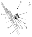
- Fig. 1 is a section of a glass pane 1, in particular a windshield of a motor vehicle, shown with adjoining sensor module 2.
- the sensor module 2 essentially comprises a module housing 3, a sensor 4, an actuating element 5, a spring element 6, a locking element 7 and a retardation element 8.
- the module housing 3 must remain in a fixed position relative to the interior windshield surface.
- the module housing 3 therefore has contact surfaces or sealing surfaces 9 on its side facing the inner surface.
- the module housing 3 has a mounting portion 10 which can be attached either directly to the headliner or body side of the window frame.
- Another way of mounting is to mount the mounting portion 10 on the frame of an overhead roof mounted on the head unit.
- a ready-to-connect roof control unit for mounting in the vehicle interior including an integrated sensor can be provided.
- the exemplary embodiment is described below on the basis of a rain sensor arranged in the sensor module 2.
- the following other sensors can also be arranged in the sensor module: light sensors, temperature sensors ....
- the module housing 3 has on one side on the inner surface of the windshield side facing an opening which opens into a receiving space 11.
- a guide member 12 is inserted, in which the sensor 4 is mounted.
- the boundary surfaces of the guide element 12 are formed as guide surfaces for the sensor 4.
- the Fig. 1 shows the sensor 4 in a first starting position, in which the measuring surface of the sensor 4 is arranged at a distance from the inner surface of the disc.
- the sensor 4 is arranged on a sensor carrier 13, which has a ball head 14 on its side facing away from the sensor 4.
- the ball head 14 is received in a corresponding arranged on an adjusting element 5 ball socket 15.
- the sensor 4 is articulated on the actuator 5.
- the adjusting element 5 is designed as a lever mounted about a rotation axis A.
- the bearing axis is defined in the region of the inside of the receiving space 11.
- a leg spring 6 is arranged below the adjusting element 5. The arrangement of the spring 6, the force required for the function of the sensor is generated.
- the Leg spring is designed as a spiral spring wire, which ends in lever-like legs. One leg is supported on the underside of the lever, the other lever is supported on the inside of the module housing 3.
- the lever is biased by the above-described arrangement in the direction of the windshield 1.
- An upward pivoting of the lever is blocked by a locking element 7.
- the locking element 7 is designed as a movable pin which engages behind a in the front region of the lever downwardly facing pawl 16.
- This lock can be repealed via a through the side wall of the module housing 3 outwardly projecting unlocking 17.
- the delay element 8 is in this case designed as a damping element and comprises, according to the illustrated embodiment, a friction brake mounted around a rotational axis B with friction surfaces of silicone.
- the friction brake is designed for this purpose as a gear that meshes in an arranged on the lever arcuate toothed segment.
- Fig. 2 the sensor module 2 with sensor 4 is shown in a second end position.
- the measuring surface of the sensor 4 is in this case with a defined and predetermined by the spring force on the inner surface of the windshield 1.
- the unlocking or locking of the sensor 4 described above can be done purely mechanically or electromechanically by means of electrical switching signal.
- this protrudes from the module housing 3 in the assembled position and is provided with a signal color. Thus, it can be visually recognized in which position the sensor 4 is located.
- the mechanical release of the previously described transmitted to the sensor 4 adjusting movement can also be done by an electrically operated locking element.
- a timer may be provided, which releases the adjusting movement of the sensor 4 from the starting position to the end position after a predetermined time. The timer thus also represents a delay element.
- the sensor 4 can be reset, for example, for assembly purposes by means of an electric motor in the starting position.
- the lock and the unlocking of the actuating element 5 can be repeated as often as desired.
- Another advantage is that the time of unlocking can be chosen freely.
- the time of contact of the sensor 4 on the windshield 1 and thus the admission of the windshield 1 can be freely selected by the contact and assembly forces during initial assembly and service. This is expediently a time that lies after the curing of the adhesive bond between the windshield 1 and the vehicle body.
- a non-inventive sensor module 20 is shown in one embodiment.
- the actuator 50 is formed here as a piston-cylinder assembly.
- piston 52 is formed here as a hollow cylinder and has in its upper end the storage of the ball head 140.
- the spring element 60 is arranged, which is designed as a conventional compression spring and on the one hand at the bottom portion of the cylinder housing 51 and on the other hand supported on a bearing member connected to the piston 52.
- the piston 52 is biased toward the windshield 1 by the arrangement described above.
- a displacement of the piston 52 in the cylinder housing 51 in the second end position of the sensor 40 is blocked by a locking element. This is not shown in the drawing.
- the locking element and a delay element in the embodiment of a timer the description of the Fig. 1 and 2 directed.
- a sealing ring made of an elastic material is inserted in the upper region of the cylinder housing 51, in which the piston 52 is guided through the cylinder housing 51 to the outside, between the cylinder housing inner surface and the piston outer surface.
- the sealing ring in this case has the function of the damping or delay element 80, so that the adjusting movement is damped from the starting position of the sensor 40 in the end position due to the friction and time-delayed.
- the sensor module can be positioned in the upper region of the windshield with low assembly risks and assembly costs and can be electrically contacted.
- the complete sensor module can be completed as a ready-to-connect roof control unit for installation in the vehicle interior.
- a pre-assembly of the roof control unit with integrated sensor outside the vehicle interior is possible.
- the vehicle assembly can be done and the Windscreen is glued in the body.
- the sensor module can be attached to the headliner and electrically connected via the attachment section.
- the triggering of the locking of the actuating element can be controlled manually or via a timer and the sensor is moved due to the biased control element and the guidance of the sensor in its end position.
- the articulated mounting of the sensor on the adjusting element allows an exact contact of the measuring surface of the sensor on the windshield.
Landscapes
- Engineering & Computer Science (AREA)
- Mechanical Engineering (AREA)
- Multimedia (AREA)
- Physics & Mathematics (AREA)
- General Physics & Mathematics (AREA)
- Automation & Control Theory (AREA)
- Measuring Fluid Pressure (AREA)
- Window Of Vehicle (AREA)
- Investigating Or Analysing Materials By Optical Means (AREA)
- Investigating Or Analyzing Materials By The Use Of Fluid Adsorption Or Reactions (AREA)
Description
- Die Erfindung betrifft ein Sensormodul, welches im Bereich einer Scheibe eines Kraftfahrzeugs angeordnet werden kann.
- Derartige Sensormodule können für verschiedene Funktionen, beispielsweise zur Sensierung des Regens, des Beschlags oder des Lichts eingesetzt werden. In einem Sensormodul können auch mehrere Funktionen integriert sein. Regensensormodule werden zur automatischen Steuerung der Scheibenwischer von Kraftfahrzeugen eingesetzt. Der Regensensor ist dabei in dem Kraftfahrzeug an der Innenseite der Windschutzscheibe angebracht und misst in diesem Bereich die Benetzung des Messfeldes durch Feuchtigkeit und Regentropfen auf der Außenseite der Windschutzscheibe.
- Für die Befestigung der Sensoren im Bereich der Windschutzscheibe sind unterschiedliche Befestigungsstellen und Befestigungsarten bekannt. Es ist bekannt, die Sensoren im Befestigungssockel des Innenrückspiegels im oberen Bereich der Windschutzscheibe zu integrieren.
- Eine im Befestigungssockel integrierte Anordnung ist aus der
DE 10 2004 007 516 A1 bekannt. Zur Erzielung einer exakten Zuordnung der Bauteile sind Mittel zur definierten gegenseitigen Zuordnung von Montagepositionen der beiden Bauteile an der Scheibe vorgesehen. Bei der Montage der beiden Bauteile wird dabei zunächst ein Sensorrahmen des Sensormoduls auf der Windschutzscheibe verklebt, und anschließend wird der Befestigungssockel über das Sensormodul gestülpt und ebenfalls mit der Scheibe verklebt. Eine Verklebung der Sensoren mit der Innenseite der Windschutzscheibe von Kraftfahrzeugen ist allerdings mit einigen Nachteilen behaftet. - Eine derartige Befestigung der Sensoren an der Windschutzscheibe erfordert hohe Montagezeiten. Des Weiteren können Montagefehler durch eine Veränderung der beabsichtigten Klebeposition der Windschutzscheibe zur Fahrzeugkarosse auftreten.
- Ein Nachteil der Verklebung des Befestigungssockels sowie des Sensors mit der Windschutzscheibe besteht zusätzlich darin, dass die Verklebung z.B. im Wartungsfall nicht zerstörungsfrei gelöst werden kann.
- Aus der
DE 101 27 070 A1 ist eine Innenspiegelanordnung mit einem im Befestigungssockel integrierten Sensor bekannt, die eine Führungsvorrichtung aufweist, welche einerseits mit dem Sensor und andererseits mit einem Stellelement verbunden ist. Bei der Endmontage wird hier durch eine Bewegung des Stellelements der Sensor an der Innenseite der Windschutzscheibe positioniert. Eine Verklebung der Sensorfläche ist bei dieser Anordnung nicht vorgesehen. - Aus der
DE 197 11 374 A1 ist ein Innenlichtmodul mit Regensensor bekannt, wobei der Regensensor im Gehäuse des Innenlichtmoduls integriert ist. Zur Erzielung einer guten Anlage des Regensensors ist der Regensensor in einer Ausnehmung des Modulgehäuses senkrecht zur Scheibeninnenfläche verschiebbar aufgenommen und wird über ein Federelement an die Innenfläche der Windschutzscheibe gedrückt. Ein gafingsgemäßes sensormodue ist aus derEP 0 803 414 A1 bekannt. - Aufgabe der vorliegenden Erfindung ist es, ein Sensormodul, welches zur Befestigung im Bereich einer Scheibe eines Kraftfahrzeugs vorgesehen ist, derart weiterzubilden, dass eine vereinfachte Montage ermöglicht wird und bei der Befestigung eine Beschädigung des Sensors möglichst ausgeschlossen werden kann.
- Diese Aufgabe wird durch die im Anspruch 1 angegebenen Merkmale gelöst. Aufgrund der Anordnung eines Verzögerungselementes und der Arretierung des Sensors in einer ersten Ausgangsposition, kann der Zeitpunkt der Positionierung des Sensors an der Windschutzscheibe in einer zweiten Endposition variabel gewählt werden. Die Verlagerung des Sensors von seiner ersten Vormontageposition (Ausgangsposition) in eine zweite Anlageposition (Endposition) kann wieder rückgängig gemacht und beliebig oft wiederholt werden.
- Das Verzögerungselement kann weiterhin ein Dämpfungselement umfassen oder als Dämpfungselement ausgebildet sein. Hierdurch wird ein Vorschnellen des Sensors an die Windschutzscheibe verhindert und es wird somit eine behutsame Positionierung des Sensors möglich.
- Die Erfindung sowie bevorzugte Ausführungsbeispiele sind in den Zeichnungen dargestellt und werden nachfolgend anhand der Beschreibung näher erläutert.
- Es zeigt:
- Fig.1 1
- eine schematische Darstellung eines Sensormoduls in Schnittdarstellung, wobei der Sensor in seiner Ausgangsposition gezeigt ist,
- Fig.2
- eine Schnittdarstellung des Sensormoduls nach
Fig. 1 , wobei der Sensor in seiner Endposition gezeigt ist, - Fig.3
- eine schematische Darstellung einer weiteren nich-erfindungsgemäßen Ausführungsform eines Sensormoduls in Schnittdarstellung
- In
Fig. 1 ist schematisch ein Ausschnitt einer Glasscheibe 1, insbesondere einer Windschutzscheibe eines Kraftfahrzeugs, mit daran anliegendem Sensormodul 2 dargestellt. Das Sensormodul 2 umfasst im Wesentlichen ein Modulgehäuse 3, einen Sensor 4, ein Stellelement 5, ein Federelement 6, ein Arretierelement 7 und ein Verzögerungselement 8 . Damit das Sensormodul 2 ordnungsgemäß arbeitet, muss das Modulgehäuse 3 in einer festen Position relativ zur Windschutzscheiben- Innenoberfläche verbleiben. Das Modulgehäuse 3 weist daher an seinen der Innenoberfläche zugewandten Seite Anlageflächen oder Dichtflächen 9 auf. Zwecks Anbringung des Modulgehäuses 3 vorzugsweise im Bereich naheliegend der oberen Scheibenkante, weist das Modulgehäuse 3 einen Befestigungsabschnitt 10 auf, der entweder unmittelbar an dem Dachhimmel oder karosserieseitig am Scheibenrahmen befestigt werden kann. Eine weitere Möglichkeit der Anbringung besteht darin, den Befestigungsabschnitt 10 auf dem Rahmen einer am Dachhimmel angebrachten Dachbedieneinheit zu montieren. Hierdurch kann eine anschlussfertige Dachbedieneinheit zur Montage in den Fahrzeuginnenraum einschließlich eines integrierten Sensors bereitgestellt werden. Das Ausführungsbeispiel wird nachfolgend anhand eines im Sensormodul 2 angeordneten Regensensors beschrieben. Es können allerdings auch folgende andere Sensoren im Sensormodul angeordnet sein: Lichtsensoren, Temperatursensoren .... - Das Modulgehäuse 3 weist einseitig auf der der Innenoberfläche der Windschutzscheibe zugewandten Seite eine Öffnung auf, die in einen Aufnahmeraum 11 mündet. In der Öffnung ist ein Führungselement 12 eingefügt, in dem der Sensor 4 gelagert ist. Die Begrenzungsflächen des Führungselementes 12 sind als Führungsflächen für den Sensor 4 ausgebildet. Die
Fig. 1 zeigt den Sensor 4 in einer ersten Ausgangsposition, in dieser ist die Meßfläche des Sensors 4 mit einem Abstand zu der Innenoberfläche der Scheibe angeordnet. Der Sensor 4 ist auf einem Sensorträger 13 angeordnet, der auf seiner dem Sensor 4 abgewandten Seite einen Kugelkopf 14 aufweist. Der Kugelkopf 14 ist in einer entsprechenden an einem Stellelement 5 angeordneten Kugelpfanne 15 aufgenommen. Somit ist der Sensor 4 auf dem Stellelement 5 gelenkig gelagert. Durch diese gelenkige Lagerung des Sensors 4 an dem Stellelement 5 kann in jedem Fall eine korrekte Kippstellung des Sensors d.h. vollflächige Anlage der Messfläche des Sensors 4 an der Innenoberfläche der Scheibe 1 sichergestellt werden. Das Stellelement 5 ist als um eine Drehachse A gelagerter Hebel ausgebildet. Die Lagerachse ist im Bereich der Innenseite des Aufnahmeraums 11 festgelegt. Aus der Zeichnung ist weiterhin zu ersehen, dass unterhalb des Stellelementes 5 eine Schenkelfeder 6 angeordnet ist. Durch die Anordnung der Feder 6 wird die für die Funktion des Sensors erforderliche Andrückkraft erzeugt. Die Schenkelfeder ist als spiralförmiger Federdraht, der in hebelartigen Schenkeln endet, ausgebildet. Ein Schenkel stützt sich an der Unterseite des Hebels ab, der andere Hebel stützt sich an der Innenseite des Modulgehäuses 3 ab. Der Hebel ist durch die obenstehend beschriebene Anordnung in Richtung auf die Windschutzscheibe 1 vorgespannt. Ein nach oben Verschwenken des Hebels wird durch ein Arretierelement 7 blockiert. Das Arretierelement 7 ist als bewegbarer Stift ausgebildet, der eine im vorderen Bereich des Hebels nach unten weisende Sperrklinke 16 hintergreift. - Diese Arretierung kann über ein durch die Seitenwand des Modulgehäuses 3 nach außen ragendes Entriegelungselement 17 aufgehoben werden. Nach Betätigung des Entriegelungselementes 17 wird ein Vorschnellen des durch die Federkraft vorgespannten Hebels mit gelenkig am Hebel gelagertem Sensor 4 durch ein im Modulgehäuse 3 angeordnetes Verzögerungselement 8 verhindert. Das Verzögerungselement 8 ist hierbei als Dämpfungselement ausgebildet und umfasst gemäß dem dargestellten Ausführungsbeispiel eine um eine Drehachse B gelagerte Reibbremse mit Reibflächen aus Silikon. Die Reibbremse ist hierfür als Zahnrad ausgebildet, dass in einem an dem Hebel angeordnetem bogenförmig verlaufenden Zahnsegment kämmt. Durch diese Ausbildung wird eine gedämpfte Stellbewegung des Sensors 4 in Richtung auf die Windschutzscheibe erzeugt. Die Gefahr einer Beschädigung des Sensors 4 durch Anschlagen an die Scheibe wird dadurch erheblich reduziert. Eine Führung des Sensors 4 in Richtung auf die Windschutzscheibe wird durch die Führungsflächen am Führungselement 12 erzielt.
- In
Fig. 2 ist das Sensormodul 2 mit Sensor 4 in einer zweiten Endposition gezeigt. Die Messfläche des Sensors 4 liegt hierbei mit einer definierten und durch die Feder vorgegebenen Kraft an der Innenoberfläche der Windschutzscheibe 1 an. - Die zuvor beschriebene Entriegelung bzw. Verriegelung des Sensors 4 kann hierbei rein mechanisch oder auch elektromechanisch mittels elektrischen Schaltsignals erfolgen. Bei der zuvor beschriebenen Ausführung des Entriegelungselementes 17, steht dieser in der Montagestellung aus dem Modulgehäuse 3 hervor und ist mit einer Signalfarbe versehen. Somit kann optisch erkannt werden, in welcher Position sich der Sensor 4 befindet. Die mechanische Auslösung der zuvor beschriebenen auf den Sensor 4 übertragenen Stellbewegung kann auch durch ein elektrisch betriebenes Arretierelement erfolgen. Hierbei kann ein Zeitglied vorgesehen sein, welches nach einer vorbestimmten Zeit, die Stellbewegung des Sensors 4 von der Ausgangsposition in die Endposition freigibt. Das Zeitglied stellt somit ebenfalls ein Verzögerungselement dar. In einer weiteren Ausführung kann der Sensor 4 z.B. für Montagezwecke mit Hilfe eines Elektromotors in die Ausgangsstellung zurückgestellt werden.
- Durch die oben beschriebene Anordnung kann die Arretierung sowie die Entriegelung des Stellelementes 5 beliebig oft wiederholt werden. Ein weiterer Vorteil besteht darin, dass der Zeitpunkt der Entriegelung frei gewählt werden kann. Damit kann der Zeitpunkt des Kontaktes des Sensors 4 an der Windschutzscheibe 1 und damit die Beaufschlagung der Windschutzscheibe 1 durch die Kontakt- und Montagekräfte bei Erstmontage und im Servicefall frei gewählt werden. Dies ist zweckmäßig ein Zeitpunkt, der nach dem Aushärten der Klebeverbindung zwischen Windschutzscheibe 1 und Fahrzeugkarosse liegt.
- In
Fig.3 ist ein nich-erfindungsgemäßes Sensormodul 20 in einer Ausgestaltung gezeigt. Im Unterschied zu dem in denFiguren 1 und2 dargestellten Ausführungsbeispiel ist hier das Stellelement 50 als Kolben-Zylinder-Anordnung ausgebildet. Der in einem Zylindergehäuse 51 verschieblich gelagerte Kolben 52 ist hier hohlzylindrisch ausgebildet und weist in seinem oberen Endbereich die Lagerung des Kugelkopfes 140 auf. Im Kolben 52 ist das Federelement 60 angeordnet, welches als übliche Druckfeder ausgebildet ist und sich einerseits am Bodenbereich des Zylindergehäuses 51 und andererseits an einem mit dem Kolben 52 verbundenen Lagerelement abstützt. Der Kolben 52 ist durch die obenstehend beschriebene Anordnung in Richtung auf die Windschutzscheibe 1 vorgespannt. Eine Verschiebung des Kolbens 52 in dem Zylindergehäuse 51 in die zweite Endposition des Sensors 40 wird durch ein Arretierelement blockiert. Dies ist in der Zeichnung nicht dargestellt. Zu den weiteren Ausgestaltungen des Arretierelementes sowie eines Verzögerungselementes in Ausgestaltung eines Zeitgliedes, wird auf die Beschreibung derFig. 1 und2 verwiesen. - Im oberen Bereich des Zylindergehäuses 51, in dem der Kolben 52 durch das Zylindergehäuse 51 nach außen geführt ist, ist zwischen Zylindergehäuse-Innenfläche und Kolbenaußenfläche ein Dichtungsring aus einem elastischen Material eingefügt. Der Dichtungsring hat hierbei die Funktion des Dämpfungs- bzw. Verzögerungselementes 80, so dass die Stellbewegung von der Ausgangsposition des Sensors 40 in die Endposition aufgrund der Reibung gedämpft und zeitverzögert erfolgt.
- Das Sensormodul kann wie nachfolgend beschrieben mit geringen Montagerisiken und Montagekosten im oberen Bereich der Windschutzscheibe positioniert und elektrisch kontaktiert werden.
- In einem ersten Schritt kann das komplette Sensormodul als anschlussfertige Dachbedieneinheit zur Montage in den Fahrzeuginnenraum fertig gestellt werden. Hierdurch wird eine Vormontage der Dachbedieneinheit mit integriertem Sensor außerhalb des Fahrzeuginnenraums möglich. Parallel hierzu kann die Fahrzeugmontage erfolgen und die Windschutzscheibe wird in der Karosse verklebt. Nach der Verklebung der Windschutzscheibe kann das Sensormodul über den Befestigungsabschnitt am Dachhimmel befestigt und elektrisch angeschlossen werden. Nachdem die Klebeverbindung Windschutzscheibe/Karosse ausgehärtet ist, kann die Auslösung der Verriegelung des Stellelementes manuell oder über ein Zeitglied gesteuert erfolgen und der Sensor wird aufgrund des vorgespannten Stellelementes und der Führung des Sensors in seine Endposition bewegt. Somit werden Montagefehler und eine Veränderung der Klebeposition der Windschutzscheibe in der Karosse nach der Positionierung des Sensors verhindert. Ein zusätzlich angeordnetes Dämpfungselement in Form einer Reibbremse, einer hydraulischen Dämpfung oder bspsw. eines Reibbelags zwischen den relativ zueinander bewegten Elementen bei der Stellbewegung, verhindert ein Vorschnellen des Sensors an die Windschutzscheibe. Damit wird eine Beschädigung des Sensors weitgehend vermieden. Die gelenkige Lagerung des Sensors an dem Stellelement ermöglicht eine exakte Anlage der Messfläche des Sensors an der Windschutzscheibe.
Claims (7)
- Sensormodul (2,20) zur lösbaren Anbringung eines Sensors (4,40) an einer Scheibe (1) eines Kraftfahrzeugs, wobei das Sensormodul (2,20) über ein an einem Modulgehäuse (3,30) angeordneten Befestigungsabschnitt (10) mit einem karosseriefesten oder einem mit einem karosseriefesten Teil In Verbindung stehenden Element verbindbar ist, wobei in dem Modulgehäuse (3,30) ein Sensor (4,40) aufgenommen ist, der von einer ersten Ausgangsposition in eine zweite Endposition zur Anlage an der Scheibe (1) verschwenkbar gehalten ist, und diese Stellbewegung Ober ein Stellelement (5,50) einleitbar ist,
und das Stellelement (5,50) mittels eines Federelementes (6,60) in Richtung auf die Endposition vorspannbar und in der Ausgangsposition über ein Arretierelement (7) arretierbar ist, dadurch gekennzeichnet, dass ein Dämpfungselement (8) vorgesehen ist, durch welches eine gedämpfte Stellbewegung des Sensors (4) in Richtung der Scheibe (1) erzeugbar ist,und, das Stelllelement (5) als drehbar gelagerter Hebel ausgebildet ist. - Sensormodul nach Anspruch 1 , wobei der Sensor (4,40) gelenkig mit dem Stellelement (5,50) verbunden ist.
- Sensormodul nach Anspruch 2, wobei die gelenkige Verbindung einen in einer Gelenkpfanne(1 5)elagerten Kugelkopf (14) umfasst.
- Sensormodul nach einem der vorangehenden Ansprüche, wobei das Federelement (6) eine Schenkelfeder ist, die sich einerseits mit einem Schenkel an der Unterseite des Hebels und andererseits mit einem Schenkel an dem Modulgehäuse abstützt.
- Sensormodul nach einem der vorangehenden Anspruch, wobei das Arretierelement (7) als horizontal bewegbarer Stift ausgebildet ist, der eine im vorderen Bereich des Hebels nach unten weisende Sperrklinke (16) hintergreift.
- Sensormodul nach einem der vorangehenden Ansprüche, wobei das Dämpfungselement (8) als Reibbremse ausgebildet ist und ein am Modulgehäuse mit einem Reibbelag versehenes Zahnrad umfasst, welches in einen am Stellelement (5) angeordneten Zahnkamm eingreift.
- Sensormodul nach einem der vorangehenden Ansprüche, wobei ein Zeitglied vorgesehen ist, welches nach einer vorbestimmten Zeit, die Stellbewegung des Sensors (4) von der Ausgangsposition in die Endposition freigibt.
Applications Claiming Priority (2)
| Application Number | Priority Date | Filing Date | Title |
|---|---|---|---|
| DE102007042694A DE102007042694A1 (de) | 2007-09-07 | 2007-09-07 | Sensormodul |
| PCT/DE2008/001421 WO2009030198A2 (de) | 2007-09-07 | 2008-08-28 | Sensormodul |
Publications (2)
| Publication Number | Publication Date |
|---|---|
| EP2185388A2 EP2185388A2 (de) | 2010-05-19 |
| EP2185388B1 true EP2185388B1 (de) | 2011-11-02 |
Family
ID=40340007
Family Applications (1)
| Application Number | Title | Priority Date | Filing Date |
|---|---|---|---|
| EP08829017A Not-in-force EP2185388B1 (de) | 2007-09-07 | 2008-08-28 | Sensormodul |
Country Status (6)
| Country | Link |
|---|---|
| US (1) | US8456317B2 (de) |
| EP (1) | EP2185388B1 (de) |
| AT (1) | ATE531589T1 (de) |
| CA (1) | CA2698415A1 (de) |
| DE (2) | DE102007042694A1 (de) |
| WO (1) | WO2009030198A2 (de) |
Families Citing this family (7)
| Publication number | Priority date | Publication date | Assignee | Title |
|---|---|---|---|---|
| DE102008027183B4 (de) * | 2008-06-06 | 2010-12-09 | Preh Gmbh | Anbau eines kapazitiven Sensors in ein Dachmodul |
| EP2241870B1 (de) * | 2009-04-17 | 2015-09-02 | Sensirion AG | Anordnung mit einem Substrat und einem gegen das Substrat gepressten Sensor |
| DE102011107353B4 (de) * | 2011-07-14 | 2022-03-24 | HELLA GmbH & Co. KGaA | Haltevorrichtung für einen Scheibensensor |
| JP6668151B2 (ja) | 2016-04-12 | 2020-03-18 | 日立オートモティブシステムズ株式会社 | 車載光学装置および車載光学システム |
| EP3279043B1 (de) | 2016-08-05 | 2018-12-05 | MEAS France | Sensormontagesystem |
| DE102019117843A1 (de) * | 2019-07-02 | 2021-01-07 | Valeo Systèmes d'Éssuyage | Wischermotor und Verfahren zu dessen Herstellung |
| CN110901588B (zh) * | 2019-12-10 | 2021-08-06 | 温州科丰汽车零部件有限公司 | 汽车雨量传感器 |
Family Cites Families (14)
| Publication number | Priority date | Publication date | Assignee | Title |
|---|---|---|---|---|
| US4316757A (en) | 1980-03-03 | 1982-02-23 | Monsanto Company | Method and apparatus for wax mounting of thin wafers for polishing |
| DE3734393A1 (de) * | 1987-10-10 | 1989-04-20 | Bernhard Mittelhaeuser | Rueckblickspiegel fuer kraftfahrzeuge |
| JP2534196B2 (ja) | 1993-12-21 | 1996-09-11 | 株式会社エンヤシステム | ウエ−ハ貼付方法 |
| US5556493A (en) | 1995-01-13 | 1996-09-17 | Libbey-Owens-Ford Co. | Mounting an optical moisture sensor on a windshield using a vacuum chamber device |
| DE19616073A1 (de) * | 1996-04-23 | 1997-10-30 | Teves Gmbh Alfred | Vorrichtung zum blasenfreien Fixieren von zu klebenden Komponenten |
| DE19711374A1 (de) | 1997-03-19 | 1998-09-24 | Itt Mfg Enterprises Inc | Innenlichtmodul mit Regensensor |
| US6326613B1 (en) * | 1998-01-07 | 2001-12-04 | Donnelly Corporation | Vehicle interior mirror assembly adapted for containing a rain sensor |
| DE19753879C1 (de) * | 1997-12-05 | 1998-12-03 | Kostal Leopold Gmbh & Co Kg | Dachmodul |
| US6690268B2 (en) | 2000-03-02 | 2004-02-10 | Donnelly Corporation | Video mirror systems incorporating an accessory module |
| DE10127070B4 (de) | 2001-05-23 | 2005-12-08 | Magna Reflex Holding Gmbh | Innenspiegelanordnung |
| US6824281B2 (en) | 2002-01-31 | 2004-11-30 | Donnelly Corporation | Vehicle accessory module |
| DE102004007516A1 (de) | 2004-02-17 | 2005-09-01 | Robert Bosch Gmbh | Anordnung zur Befestigung eines Rückspiegels und eines optischen Sensors |
| DE202006017362U1 (de) * | 2006-11-13 | 2008-03-20 | Trw Automotive Electronics & Components Gmbh & Co. Kg | Regensensor |
| DE102008044839A1 (de) * | 2008-08-28 | 2010-03-04 | Leopold Kostal Gmbh & Co. Kg | Sensoranordnung für ein Kraftfahrzeug |
-
2007
- 2007-09-07 DE DE102007042694A patent/DE102007042694A1/de not_active Withdrawn
-
2008
- 2008-08-28 DE DE112008003008T patent/DE112008003008A5/de not_active Withdrawn
- 2008-08-28 AT AT08829017T patent/ATE531589T1/de active
- 2008-08-28 EP EP08829017A patent/EP2185388B1/de not_active Not-in-force
- 2008-08-28 US US12/676,624 patent/US8456317B2/en not_active Expired - Fee Related
- 2008-08-28 WO PCT/DE2008/001421 patent/WO2009030198A2/de not_active Ceased
- 2008-08-28 CA CA2698415A patent/CA2698415A1/en not_active Abandoned
Also Published As
| Publication number | Publication date |
|---|---|
| WO2009030198A8 (de) | 2010-04-08 |
| DE112008003008A5 (de) | 2010-08-19 |
| EP2185388A2 (de) | 2010-05-19 |
| US8456317B2 (en) | 2013-06-04 |
| CA2698415A1 (en) | 2009-03-12 |
| WO2009030198A3 (de) | 2009-07-23 |
| US20100308094A1 (en) | 2010-12-09 |
| DE102007042694A1 (de) | 2009-03-12 |
| ATE531589T1 (de) | 2011-11-15 |
| WO2009030198A2 (de) | 2009-03-12 |
Similar Documents
| Publication | Publication Date | Title |
|---|---|---|
| EP2185388A2 (de) | Sensormodul | |
| EP1444114B1 (de) | Halterung für ein justierbares gehäuse | |
| EP2112021B1 (de) | Scheinwerfer für Fahrzeuge | |
| EP2070761A3 (de) | Getriebebaueinheit einer Verstelleinrichtung eines Kraftfahrzeugs | |
| DE10060447B4 (de) | Innenspiegelanordnung | |
| DE102023107080A1 (de) | Stellvorrichtung | |
| EP1593550A1 (de) | Innenspiegel mit Antriebseinrichtung zur Verstellung eines Keilspiegelglases | |
| EP1196308B1 (de) | Antriebsvorrichtung für einen verstellbaren kraftfahrzeugspiegel unter verwendung eines selbstkalibrierenden potentiometers | |
| DE29914042U1 (de) | Türscharnier für Kraftfahrzeugtüren mit integriertem Feststeller | |
| DE4134201C1 (en) | Covered internal trimming fixture for car bodywork - uses form-fitting snap arrangement allowing release without damage for servicing | |
| DE19528789C1 (de) | Verschlußanordnung für ein bewegliches Karosserieteil | |
| DE102016211029A1 (de) | Längseinsteller für einen Fahrzeugsitz und Fahrzeugsitz | |
| DE202005000559U1 (de) | Antriebsanordnung zur Betätigung der Klappe eines Kraftfahrzeugs | |
| DE102004017322A1 (de) | Trommelgehäuse | |
| DE102005041636B4 (de) | Verstelleinrichtung zur Einstellung eines Kraftfahrzeugteiles | |
| DE3841719C2 (de) | ||
| DE202009009459U1 (de) | Mitnehmer zur Anbindung einer Fensterscheibe an einen Fensterheber eines Kraftfahrzeugs | |
| EP2977532B1 (de) | Außengriffsystem für eine Fahrzeugtür | |
| DE102009003189A1 (de) | Scheibenwischervorrichtung | |
| EP1935729A2 (de) | Scheibenwischvorrichtung in einem Fahrzeug | |
| WO2009027321A1 (de) | Sensoranordnung | |
| DE10003917B4 (de) | Haltevorrichtung für eine Zierfigur eines Kraftfahrzeuges | |
| DE10127070A1 (de) | Innenspiegelanordnung | |
| EP1940658B1 (de) | Befestigungseinrichtung | |
| DE10325350A1 (de) | Spiegelanordnung an einer Windschutzscheibe eines Kraftfahrzeuges |
Legal Events
| Date | Code | Title | Description |
|---|---|---|---|
| PUAI | Public reference made under article 153(3) epc to a published international application that has entered the european phase |
Free format text: ORIGINAL CODE: 0009012 |
|
| 17P | Request for examination filed |
Effective date: 20100329 |
|
| AK | Designated contracting states |
Kind code of ref document: A2 Designated state(s): AT BE BG CH CY CZ DE DK EE ES FI FR GB GR HR HU IE IS IT LI LT LU LV MC MT NL NO PL PT RO SE SI SK TR |
|
| GRAP | Despatch of communication of intention to grant a patent |
Free format text: ORIGINAL CODE: EPIDOSNIGR1 |
|
| DAX | Request for extension of the european patent (deleted) | ||
| GRAS | Grant fee paid |
Free format text: ORIGINAL CODE: EPIDOSNIGR3 |
|
| GRAA | (expected) grant |
Free format text: ORIGINAL CODE: 0009210 |
|
| AK | Designated contracting states |
Kind code of ref document: B1 Designated state(s): AT BE BG CH CY CZ DE DK EE ES FI FR GB GR HR HU IE IS IT LI LT LU LV MC MT NL NO PL PT RO SE SI SK TR |
|
| REG | Reference to a national code |
Ref country code: GB Ref legal event code: FG4D Free format text: NOT ENGLISH |
|
| REG | Reference to a national code |
Ref country code: CH Ref legal event code: EP |
|
| REG | Reference to a national code |
Ref country code: IE Ref legal event code: FG4D |
|
| REG | Reference to a national code |
Ref country code: DE Ref legal event code: R096 Ref document number: 502008005477 Country of ref document: DE Effective date: 20120112 |
|
| REG | Reference to a national code |
Ref country code: NL Ref legal event code: VDEP Effective date: 20111102 |
|
| LTIE | Lt: invalidation of european patent or patent extension |
Effective date: 20111102 |
|
| PG25 | Lapsed in a contracting state [announced via postgrant information from national office to epo] |
Ref country code: IS Free format text: LAPSE BECAUSE OF FAILURE TO SUBMIT A TRANSLATION OF THE DESCRIPTION OR TO PAY THE FEE WITHIN THE PRESCRIBED TIME-LIMIT Effective date: 20120302 Ref country code: NO Free format text: LAPSE BECAUSE OF FAILURE TO SUBMIT A TRANSLATION OF THE DESCRIPTION OR TO PAY THE FEE WITHIN THE PRESCRIBED TIME-LIMIT Effective date: 20120202 Ref country code: LT Free format text: LAPSE BECAUSE OF FAILURE TO SUBMIT A TRANSLATION OF THE DESCRIPTION OR TO PAY THE FEE WITHIN THE PRESCRIBED TIME-LIMIT Effective date: 20111102 |
|
| PG25 | Lapsed in a contracting state [announced via postgrant information from national office to epo] |
Ref country code: NL Free format text: LAPSE BECAUSE OF FAILURE TO SUBMIT A TRANSLATION OF THE DESCRIPTION OR TO PAY THE FEE WITHIN THE PRESCRIBED TIME-LIMIT Effective date: 20111102 Ref country code: PT Free format text: LAPSE BECAUSE OF FAILURE TO SUBMIT A TRANSLATION OF THE DESCRIPTION OR TO PAY THE FEE WITHIN THE PRESCRIBED TIME-LIMIT Effective date: 20120302 Ref country code: LV Free format text: LAPSE BECAUSE OF FAILURE TO SUBMIT A TRANSLATION OF THE DESCRIPTION OR TO PAY THE FEE WITHIN THE PRESCRIBED TIME-LIMIT Effective date: 20111102 Ref country code: SE Free format text: LAPSE BECAUSE OF FAILURE TO SUBMIT A TRANSLATION OF THE DESCRIPTION OR TO PAY THE FEE WITHIN THE PRESCRIBED TIME-LIMIT Effective date: 20111102 Ref country code: HR Free format text: LAPSE BECAUSE OF FAILURE TO SUBMIT A TRANSLATION OF THE DESCRIPTION OR TO PAY THE FEE WITHIN THE PRESCRIBED TIME-LIMIT Effective date: 20111102 Ref country code: SI Free format text: LAPSE BECAUSE OF FAILURE TO SUBMIT A TRANSLATION OF THE DESCRIPTION OR TO PAY THE FEE WITHIN THE PRESCRIBED TIME-LIMIT Effective date: 20111102 Ref country code: PL Free format text: LAPSE BECAUSE OF FAILURE TO SUBMIT A TRANSLATION OF THE DESCRIPTION OR TO PAY THE FEE WITHIN THE PRESCRIBED TIME-LIMIT Effective date: 20111102 Ref country code: GR Free format text: LAPSE BECAUSE OF FAILURE TO SUBMIT A TRANSLATION OF THE DESCRIPTION OR TO PAY THE FEE WITHIN THE PRESCRIBED TIME-LIMIT Effective date: 20120203 |
|
| REG | Reference to a national code |
Ref country code: IE Ref legal event code: FD4D |
|
| PG25 | Lapsed in a contracting state [announced via postgrant information from national office to epo] |
Ref country code: CY Free format text: LAPSE BECAUSE OF FAILURE TO SUBMIT A TRANSLATION OF THE DESCRIPTION OR TO PAY THE FEE WITHIN THE PRESCRIBED TIME-LIMIT Effective date: 20111102 |
|
| PG25 | Lapsed in a contracting state [announced via postgrant information from national office to epo] |
Ref country code: CZ Free format text: LAPSE BECAUSE OF FAILURE TO SUBMIT A TRANSLATION OF THE DESCRIPTION OR TO PAY THE FEE WITHIN THE PRESCRIBED TIME-LIMIT Effective date: 20111102 Ref country code: DK Free format text: LAPSE BECAUSE OF FAILURE TO SUBMIT A TRANSLATION OF THE DESCRIPTION OR TO PAY THE FEE WITHIN THE PRESCRIBED TIME-LIMIT Effective date: 20111102 Ref country code: SK Free format text: LAPSE BECAUSE OF FAILURE TO SUBMIT A TRANSLATION OF THE DESCRIPTION OR TO PAY THE FEE WITHIN THE PRESCRIBED TIME-LIMIT Effective date: 20111102 Ref country code: IE Free format text: LAPSE BECAUSE OF FAILURE TO SUBMIT A TRANSLATION OF THE DESCRIPTION OR TO PAY THE FEE WITHIN THE PRESCRIBED TIME-LIMIT Effective date: 20111102 Ref country code: BG Free format text: LAPSE BECAUSE OF FAILURE TO SUBMIT A TRANSLATION OF THE DESCRIPTION OR TO PAY THE FEE WITHIN THE PRESCRIBED TIME-LIMIT Effective date: 20120202 Ref country code: EE Free format text: LAPSE BECAUSE OF FAILURE TO SUBMIT A TRANSLATION OF THE DESCRIPTION OR TO PAY THE FEE WITHIN THE PRESCRIBED TIME-LIMIT Effective date: 20111102 |
|
| PG25 | Lapsed in a contracting state [announced via postgrant information from national office to epo] |
Ref country code: RO Free format text: LAPSE BECAUSE OF FAILURE TO SUBMIT A TRANSLATION OF THE DESCRIPTION OR TO PAY THE FEE WITHIN THE PRESCRIBED TIME-LIMIT Effective date: 20111102 Ref country code: IT Free format text: LAPSE BECAUSE OF FAILURE TO SUBMIT A TRANSLATION OF THE DESCRIPTION OR TO PAY THE FEE WITHIN THE PRESCRIBED TIME-LIMIT Effective date: 20111102 |
|
| PLBE | No opposition filed within time limit |
Free format text: ORIGINAL CODE: 0009261 |
|
| STAA | Information on the status of an ep patent application or granted ep patent |
Free format text: STATUS: NO OPPOSITION FILED WITHIN TIME LIMIT |
|
| 26N | No opposition filed |
Effective date: 20120803 |
|
| REG | Reference to a national code |
Ref country code: DE Ref legal event code: R097 Ref document number: 502008005477 Country of ref document: DE Effective date: 20120803 |
|
| BERE | Be: lapsed |
Owner name: MAGNA ELECTRONICS EUROPE G.M.B.H. & CO. KG Effective date: 20120831 |
|
| REG | Reference to a national code |
Ref country code: CH Ref legal event code: PL |
|
| PG25 | Lapsed in a contracting state [announced via postgrant information from national office to epo] |
Ref country code: MC Free format text: LAPSE BECAUSE OF NON-PAYMENT OF DUE FEES Effective date: 20120831 |
|
| PG25 | Lapsed in a contracting state [announced via postgrant information from national office to epo] |
Ref country code: ES Free format text: LAPSE BECAUSE OF FAILURE TO SUBMIT A TRANSLATION OF THE DESCRIPTION OR TO PAY THE FEE WITHIN THE PRESCRIBED TIME-LIMIT Effective date: 20120213 Ref country code: LI Free format text: LAPSE BECAUSE OF NON-PAYMENT OF DUE FEES Effective date: 20120831 Ref country code: CH Free format text: LAPSE BECAUSE OF NON-PAYMENT OF DUE FEES Effective date: 20120831 |
|
| PG25 | Lapsed in a contracting state [announced via postgrant information from national office to epo] |
Ref country code: BE Free format text: LAPSE BECAUSE OF NON-PAYMENT OF DUE FEES Effective date: 20120831 |
|
| PG25 | Lapsed in a contracting state [announced via postgrant information from national office to epo] |
Ref country code: FI Free format text: LAPSE BECAUSE OF FAILURE TO SUBMIT A TRANSLATION OF THE DESCRIPTION OR TO PAY THE FEE WITHIN THE PRESCRIBED TIME-LIMIT Effective date: 20111102 |
|
| PGFP | Annual fee paid to national office [announced via postgrant information from national office to epo] |
Ref country code: DE Payment date: 20130821 Year of fee payment: 6 |
|
| PG25 | Lapsed in a contracting state [announced via postgrant information from national office to epo] |
Ref country code: MT Free format text: LAPSE BECAUSE OF FAILURE TO SUBMIT A TRANSLATION OF THE DESCRIPTION OR TO PAY THE FEE WITHIN THE PRESCRIBED TIME-LIMIT Effective date: 20111102 |
|
| PGFP | Annual fee paid to national office [announced via postgrant information from national office to epo] |
Ref country code: GB Payment date: 20130821 Year of fee payment: 6 Ref country code: FR Payment date: 20130823 Year of fee payment: 6 |
|
| PG25 | Lapsed in a contracting state [announced via postgrant information from national office to epo] |
Ref country code: TR Free format text: LAPSE BECAUSE OF FAILURE TO SUBMIT A TRANSLATION OF THE DESCRIPTION OR TO PAY THE FEE WITHIN THE PRESCRIBED TIME-LIMIT Effective date: 20111102 |
|
| PG25 | Lapsed in a contracting state [announced via postgrant information from national office to epo] |
Ref country code: LU Free format text: LAPSE BECAUSE OF NON-PAYMENT OF DUE FEES Effective date: 20120828 |
|
| PG25 | Lapsed in a contracting state [announced via postgrant information from national office to epo] |
Ref country code: HU Free format text: LAPSE BECAUSE OF FAILURE TO SUBMIT A TRANSLATION OF THE DESCRIPTION OR TO PAY THE FEE WITHIN THE PRESCRIBED TIME-LIMIT Effective date: 20080828 |
|
| REG | Reference to a national code |
Ref country code: AT Ref legal event code: MM01 Ref document number: 531589 Country of ref document: AT Kind code of ref document: T Effective date: 20130828 |
|
| PG25 | Lapsed in a contracting state [announced via postgrant information from national office to epo] |
Ref country code: AT Free format text: LAPSE BECAUSE OF NON-PAYMENT OF DUE FEES Effective date: 20130828 |
|
| REG | Reference to a national code |
Ref country code: DE Ref legal event code: R119 Ref document number: 502008005477 Country of ref document: DE |
|
| GBPC | Gb: european patent ceased through non-payment of renewal fee |
Effective date: 20140828 |
|
| REG | Reference to a national code |
Ref country code: FR Ref legal event code: ST Effective date: 20150430 |
|
| REG | Reference to a national code |
Ref country code: DE Ref legal event code: R119 Ref document number: 502008005477 Country of ref document: DE Effective date: 20150303 |
|
| PG25 | Lapsed in a contracting state [announced via postgrant information from national office to epo] |
Ref country code: DE Free format text: LAPSE BECAUSE OF NON-PAYMENT OF DUE FEES Effective date: 20150303 Ref country code: GB Free format text: LAPSE BECAUSE OF NON-PAYMENT OF DUE FEES Effective date: 20140828 |
|
| PG25 | Lapsed in a contracting state [announced via postgrant information from national office to epo] |
Ref country code: FR Free format text: LAPSE BECAUSE OF NON-PAYMENT OF DUE FEES Effective date: 20140901 |