EP2185846B1 - Soupape à gaz à vitesse d'ouverture et d'écoulement des gaz élevée - Google Patents
Soupape à gaz à vitesse d'ouverture et d'écoulement des gaz élevée Download PDFInfo
- Publication number
- EP2185846B1 EP2185846B1 EP08800265.4A EP08800265A EP2185846B1 EP 2185846 B1 EP2185846 B1 EP 2185846B1 EP 08800265 A EP08800265 A EP 08800265A EP 2185846 B1 EP2185846 B1 EP 2185846B1
- Authority
- EP
- European Patent Office
- Prior art keywords
- rod
- valve
- gas
- force
- outlet
- Prior art date
- Legal status (The legal status is an assumption and is not a legal conclusion. Google has not performed a legal analysis and makes no representation as to the accuracy of the status listed.)
- Active
Links
Images


Classifications
-
- F—MECHANICAL ENGINEERING; LIGHTING; HEATING; WEAPONS; BLASTING
- F16—ENGINEERING ELEMENTS AND UNITS; GENERAL MEASURES FOR PRODUCING AND MAINTAINING EFFECTIVE FUNCTIONING OF MACHINES OR INSTALLATIONS; THERMAL INSULATION IN GENERAL
- F16K—VALVES; TAPS; COCKS; ACTUATING-FLOATS; DEVICES FOR VENTING OR AERATING
- F16K31/00—Actuating devices; Operating means; Releasing devices
- F16K31/12—Actuating devices; Operating means; Releasing devices actuated by fluid
- F16K31/122—Actuating devices; Operating means; Releasing devices actuated by fluid the fluid acting on a piston
-
- F—MECHANICAL ENGINEERING; LIGHTING; HEATING; WEAPONS; BLASTING
- F16—ENGINEERING ELEMENTS AND UNITS; GENERAL MEASURES FOR PRODUCING AND MAINTAINING EFFECTIVE FUNCTIONING OF MACHINES OR INSTALLATIONS; THERMAL INSULATION IN GENERAL
- F16K—VALVES; TAPS; COCKS; ACTUATING-FLOATS; DEVICES FOR VENTING OR AERATING
- F16K31/00—Actuating devices; Operating means; Releasing devices
- F16K31/02—Actuating devices; Operating means; Releasing devices electric; magnetic
- F16K31/06—Actuating devices; Operating means; Releasing devices electric; magnetic using a magnet, e.g. diaphragm valves, cutting off by means of a liquid
- F16K31/0644—One-way valve
- F16K31/0655—Lift valves
-
- F—MECHANICAL ENGINEERING; LIGHTING; HEATING; WEAPONS; BLASTING
- F16—ENGINEERING ELEMENTS AND UNITS; GENERAL MEASURES FOR PRODUCING AND MAINTAINING EFFECTIVE FUNCTIONING OF MACHINES OR INSTALLATIONS; THERMAL INSULATION IN GENERAL
- F16K—VALVES; TAPS; COCKS; ACTUATING-FLOATS; DEVICES FOR VENTING OR AERATING
- F16K31/00—Actuating devices; Operating means; Releasing devices
- F16K31/44—Mechanical actuating means
- F16K31/56—Mechanical actuating means without stable intermediate position, e.g. with snap action
-
- B—PERFORMING OPERATIONS; TRANSPORTING
- B60—VEHICLES IN GENERAL
- B60R—VEHICLES, VEHICLE FITTINGS, OR VEHICLE PARTS, NOT OTHERWISE PROVIDED FOR
- B60R21/00—Arrangements or fittings on vehicles for protecting or preventing injuries to occupants or pedestrians in case of accidents or other traffic risks
- B60R21/01—Electrical circuits for triggering passive safety arrangements, e.g. airbags, safety belt tighteners, in case of vehicle accidents or impending vehicle accidents
- B60R21/017—Electrical circuits for triggering passive safety arrangements, e.g. airbags, safety belt tighteners, in case of vehicle accidents or impending vehicle accidents including arrangements for providing electric power to safety arrangements or their actuating means, e.g. to pyrotechnic fuses or electro-mechanic valves
Definitions
- the invention relates to gas valves with high speed opening and high speed gas flow capability.
- Airbag deployment systems basically include an airbag and an inflator.
- the inflator generates and releases the gas necessary to inflate the airbag.
- the inflator is triggered by the destruction of a rupture disc, which releases the gas to fill the airbag in a mere fraction of a second.
- a separate, re-usable valve apparatus is desired to simulate the destruction of the rupture disc and subsequent inflation of the airbag.
- a valve must perform consistently and accurately so that it does not skew data being collected or introduce error into the tests.
- These valves must also deploy extremely quickly to properly simulate actual airbag deployment.
- a typical simulation gas valve inflator may need to consistently open a one inch diameter valve in 2ms.
- suitable gas valves for this purpose do not appear to be commercially available which can properly simulate actual airbag deployment in a nondestructive manner.
- United States Patent No. 4,635,855 (Kuyel et al. ) teaches a method and apparatus for rapidly controlling a flow of gas which utilizes a conductive disc to seal an orifice of a plenum holding the gas, and an electrode located proximate to the plate. By applying a current through the electrode, an eddy current is induced in the disc, which creates a repulsion force that repels the disc away from the electrode for opening the orifice.
- the repulsion force must overcome a force due to pressure of the gas stored in the plenum, and therefore, is too slow and inconsistent to be used in an airbag deployment simulation.
- the apparatus taught in this reference would open even slower, or perhaps not at all, when used with gases having significantly high pressures, as the repulsion force would have to be incredibly high to overcome the force due to pressure.
- Japanese Patent Publication No. JP58191380 (Kazuo ) teaches a gas valve which utilizes induced eddy currents in a plate coupled to a rod to open or close the valve by varying the current passing through permanent magnets located proximate to the plate.
- the system taught in this reference must overcome a force on the plate due to a pressure of the gas, and therefore, is too slow and inconsistent to be used to test airbag deployment.
- the system taught in this reference would open even slower, or perhaps not at all, when used with gases having significantly high pressures, as the repulsion force would have to be incredibly high to overcome the force due to pressure.
- the US patent US 3,785,612 discloses a quick acting valve apparatus according to the preamble of claim 1.
- a piston is moveable in a casing and separating an upper chamber from a lower chamber within the casing.
- the piston contains an electromagnet.
- pressurized air from the upper chamber is allowed to escape to the atmosphere, pressurized air in the lower chamber moves the piston upwards.
- the electromagnet attracts a holding plate connected to a valve disc via a stem, thus raising the valve disc, opening the valve. For some applications the opening speed of this valve is not sufficient.
- the present invention broadly comprises a high speed gas valve apparatus including a reservoir for holding a gas having a charge port for filling the reservoir with the gas and an outlet for releasing the gas from the reservoir, a rod slidingly housed in the valve apparatus, the rod including a sealing means operatively arranged to engage with the outlet of the valve chamber for sealing the reservoir when the valve is in a closed position, a pneumatic actuator, wherein a piston of the pneumatic actuator is coupled to the rod, an electro-magnetic actuator coupled to the rod, and wherein the gas is released from the reservoir via the outlet when the apparatus is in an open position, and the valve transitions from the closed position to the open position by activating the pneumatic and electro-magnetic actuators to move the rod away from the outlet.
- the valve apparatus further includes a first chamber and a second chamber located on opposite sides of the piston of the pneumatic actuator, wherein the gas in the reservoir has a first pressure that exerts a first force on the rod in a first direction for maintaining the valve in the closed position by forcing the sealing means of the rod to remain engaged with the outlet, wherein a second pressure in the first chamber exerts a second force on the piston in the first direction for forcing the sealing means of the rod to engage with the outlet, wherein a third pressure in the second chamber exerts a third force on the piston in a second direction, wherein the second direction is opposite from the first direction, and wherein subsequent to an activation of the pneumatic actuator, but preceding an activation of the electro-magnetic actuator, a sum of the first and second forces is greater than the third force.
- the third force is slightly less than the sum of the first and second forces for substantially reducing a net force required by the electro-magnetic actuator to transition the valve from the closed position into the open position.
- the electro-magnetic actuator comprises an electronic coil and an electrically conductive plate, wherein the plate is fixedly secured to the rod and located proximate to the coil when the valve is in the closed position, wherein the coil is electronically connected to a capacitor, wherein the electro-magnetic actuator is activated by discharging a current from the capacitor through the coil for creating a first magnetic field, wherein the first magnetic field induces a second magnetic field in the plate, and the second magnetic field is oppositely polarized with respect to the first magnetic field, wherein a repulsion force is created due to the first and second magnetic fields being oppositely polarized, and the repulsion force repels the plate away from the coil for transitioning the valve from the closed position to the open position by moving the rod away from the outlet.
- the current invention also broadly comprises a method of operating a gas valve compnsising the steps of: (a) pressurizing a first chamber in a pneumatic actuator, wherein a second pressure in the first chamber exerts a second force in a first direction on a piston of the pneumatic actuator, wherein the piston is coupled to a rod, for entering the valve into a closed position by forcing the rod to engage with an outlet of a reservoir of the gas valve; (b) pressurizing a reservoir of the gas valve with a gas having a first pressure; (c) depressurizing the first chamber in the pneumatic actuator for reducing the second pressure and the second force, wherein the gas in the reservoir exerts a first force due to the first pressure in the first direction on the piston for maintaining the valve in the closed position by forcing the rod to stay engaged with the outlet; (d) pressurizing a second chamber in the pneumatic actuator located on an opposite side of the piston from the first chamber, wherein a third pressure in the second chamber exerts a third force on the piston in a second direction
- step (e) activating the electro-magnetic actuator in step (e) further comprises discharging a current through an electronic coil for creating a first magnetic field, wherein the electronic coil is located proximate to a plate which is fixedly secured to the rod, wherein the first magnetic field induces a second magnetic field in the plate, and the second magnetic field is polarized oppositely with respect to the first magnetic field, wherein a repulsion force is created due to the first and second magnetic fields being oppositely polarized, and the repulsion force repels the plate from the coil for transitioning the valve from the closed position to the open position by forcing the rod away from the outlet.
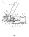
- FIG. 1 illustrates high speed gas valve 10, according to the current invention.
- Gas valve 10 includes valve body 12 that defines valve chamber or reservoir 14, which includes auxiliary inlet 16 , outlet 18 , and valve charge port 19.
- Auxiliary charge vessel 20 is detachably securable to inlet 16 and orifice bar 22 is detachably securable proximate to outlet 18 .
- auxiliary charge vessel 20 is attached to reservoir 14 so that the volume of gas that valve 10 can hold is variably changeable.
- auxiliary vessels of .5L, .75L, or 1 L could be attached via inlet 16 to increase the volume of gas in valve apparatus 10 to 1.5L, 1.75L, and 2L, respectively.
- Orifice bar 22 includes a hole that is aligned with outlet 18 for determining the flow characteristics of gas released from chamber 14 via outlet 18. For example, it may be desirable to increase or decrease the exit velocity or mass flow rate of the gas from the outlet by varying the size of the hole in the orifice bar.
- Valve sealing member 24 which includes valve sealing ring 25 is included on one end of rod 26.
- the rod is slidingly movable within the valve apparatus for selectably sealing and opening outlet 18. That is, valve closure member 24, which resembles a large bulb on the end of rod 26, is pressed into outlet 18 to create an airtight seal with the aid of sealing ring 25.
- the sealing member alone or together with the sealing ring comprises a sealing means for the valve.
- Sealing ring 25 is preferably a flexible and resilient o-ring fabricated from any number of polymers or other suitable materials.
- a second end of rod 26, opposite from valve sealing member 24, extends into housing 30, which is secured to valve body 12.
- Housing 30 is preferably fixed to an immobile object via mount 31, which may use bolts (not shown) or some other means known in the art to secure valve 10 in place.
- the second end of rod 26 is affixed to piston 32, which is slidingly mounted within cylinder 34, which in turn is mounted in housing 30.
- Piston 32 and cylinder 34 are components of pneumatic actuator 36, which may be any pneumatic actuator known in the art, including those that are commonly available commercially, but which preferably takes the general form shown in the Figures and described herein.
- Plate 40 is mounted to an intermediate portion of rod 26 between sealing member 24 and pneumatic actuator 36.
- the disc is located adjacent to electrical coil L 1 when the valve is in a closed position.
- closed position we mean that sealing means 24 on rod 26 is engaged in a sealed relation with outlet 18 so that no gas stored in reservoir 14 can escape the reservoir through the outlet.
- the coil is fixedly mounted to housing 30 so that it is immovable with respect to valve 10. Plate 40 and coil L 1 are components of electro-magnetic actuator 44.
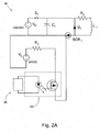
- main circuit 46 for electro-magnetic actuator 44 is shown schematically in Figure 2A .
- the circuit includes coil L 1 , high voltage power source V H , capacitor C 1 , resistors R 1 and R 2 , diode D 1 , silicon-controlled rectifier SCR 1 , switch S 1 , optocoupler OC, control circuit 48 and low voltage source V L .
- High voltage supply V H is used to charge capacitor C 1 , which stores the energy dissipated by the high voltage power source.
- Silicon-controlled rectifier SCR 1 acts as a high-speed switch for delivering the energy from capacitor C 1 to coil L 1 .
- Diode D 1 is connected across coil L 1 to protect the other components of the circuit from the back EMF generated by the rapid collapsing magnetic field in the coil.
- Optocoupler OC electronically isolates control circuit 48 and sends signals in the form of light or optics from the control circuit to operate main circuit 46.
- Control circuit 48 may send signals via the optocoupler to open and close switch S 1 or turn the SCR on and off, for example.
- Low voltage power supply V L provides a low voltage to the gate of the SCR to enable the SCR to operate.
- the resistance of resistor R 2 is chosen to regulate the voltage that is applied to gate G, as is well known to those having ordinary skill in the art of circuit design.
- Figures 2B and 2C show a schematic of the relevant portion of circuit 46 and plate 40 when switch S 1 is opened and closed, respectively.
- switch S 1 When switch S 1 is open no current passes through the coil.
- switch S 1 When switch S 1 is closed, as in Figure 2C , large currents (several hundred amperes, for example) are generated because of the high voltage and capacitance, and extremely short discharge time of the capacitor, causing the coil to produce a powerful increasing magnetic field 42a, which passes through plate 40.
- magnetic field 42a While passing through the plate, magnetic field 42a induces eddy currents 50 in the direction indicated by arrow 52, which is opposite to the direction of current through the coil, as indicated by arrow 54.
- the induced current in plate 40 generates magnetic field 40a oppositely polarized with respect to magnetic field 42a, as fields 40a and 42a act generally in the direction of arrows 58 and 56, respectively.
- the two oppositely polarized magnetic fields generate a large repulsive force between the coil and the plate.
- the coil cannot move, as it is fixedly secured to housing 30 which is immovably anchored by valve mount 31. Consequently, the repulsive force rapidly repels plate 40 from coil L 1 . Since the plate is fixedly secured to the rod, the plate and the rod are forced in direction 58 away from outlet 18, to open outlet of valve 10.
- circuit 46 The following describes the parameters of a preferred embodiment of circuit 46, as shown in Figure 2 , but it should be understood that the circuit could have other parameters readily recognizable by one skilled in the art.
- the values of the capacitance, inductance and resistance should be chosen such that they create a critically damped circuit.
- the below embodiment is designed to produce approximately a 2670 N (600 lb) force for 200 ⁇ s between plate 40 and coil L 1 , with the total energy being dissipated in about 500 ⁇ s.
- coil L 1 has an inductance of approximately 2mH
- high voltage power source V H is a 2000VDC
- 60mA power supply capacitor C has a capacitance of 150 ⁇ F
- resistor R 1 is achieved by approximately 1 ⁇ of inherent wire resistance so that an actual resistor is not used
- low voltage source V L is a 24VDC power supply.
- the overall length of the coil should be kept to a minimum and the plate should be kept as close to the coil as possible.
- ribbon wire is preferably used instead of traditional magnetic wire.
- plate 40 is made of aluminum because it is lightweight and produces a sufficient magnetic field.
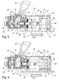
- valve is shown in an initial, open state in a cross-sectional view in Figure 3 .
- open we mean that sealing member 24 on rod 26 is not in a sealed relation with outlet 18 so that gas can freely escape the outlet from reservoir 14.
- Pneumatic actuator 36 includes chambers 60 and 62 on opposite sides of piston 32 in cylinder 34. Chamber 60 cannot be seen in Figure 3 as the piston is pushed to the far right side of the cylinder, leaving no room for chamber 60.
- Pressures P 1 , P 2 , and P 3 represent the pressures in chambers 14, 60, and 62, respectively. In the initial state as shown in this Figure, all of the pressures are substantially equal to the atmospheric pressure, and the system is therefore balanced and in equilibrium.
- atmospheric pressure we mean the pressure of the room or area in which valve 10 is housed.
- Valve 10 is shown in a closed position in Figure 4 .
- closed position we mean that sealing member 24 engages outlet 18 for making reservoir 14 airtight.
- An activation of pneumatic actuator 36 forces rod 26 into the closed position shown.
- the activation of pneumatic actuator 36 comprises pressurizing chamber 60 so that pressure P 2 is high enough to exert a force to move piston 32, and therefore rod 26 and sealing member 24, towards outlet 18.
- pressure P 2 is about 172 kPa (25 psig).
- reservoir 14 is filled with a high pressure gas having pressure P 1 via charge port 19 as indicated by arrow 64.
- pressure P 1 is about 20,7 MPa (3000 psig) but it could be other pressures, as desired.
- auxiliary vessel 20 If auxiliary vessel 20 is present, the gas from charge port 19 will also fill the charge vessel, which is initially empty. Pressures P 1 and P 2 exert first and second forces on rod 26 (indirectly through piston 32 and sealing member 24, respectively) in the direction indicated by arrow 56 toward the outlet.
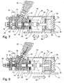
- chamber 60 is depressurized so that pressure P 2 returns to approximately atmospheric pressure, as shown in Figure 6 .
- rod 26 is held in sealed engagement with the outlet due to pressure P 1 exerting a force on sealing member 24 of the rod.
- the valve reservoir is storing the gas that is desired to be released when the outlet is opened, such as, for example, the gas necessary to fill an airbag in an airbag inflation test. It may be desirable to leave pressure P 2 at a relatively low value, such as 70 kPa (10 psig) so that it can cushion the cylinder from the piston when electro-magnetic actuator 44 is fired, as will be described later.
- chamber 62 is then pressurized so that it contains pressure P 3 .
- Pressure P 3 exerts a third force in the direction of arrow 58 on piston 32, which transfers the third force to rod 26 and sealing member 24.
- Pressure P 3 is preferably increased to a point at which outlet 18 is just about to open, but at which the outlet is still completely sealed. That is, the magnitude of the force due to pressure P 3 in direction 58 is just less than a sum of the forces due to pressures P 1 and P 2 in direction 56.
- pressure P 3 varies between approximately 172-862 kPa (25-125 psig) during this phase.
- valve 10 If pressure P 3 were increased enough, so that the force in the direction of arrow 58 were higher than force due to pressure P 1 in the direction of arrow 56, the rod would be forced to move in direction 58, thereby opening outlet 18 by breaking the sealed engagement of the sealing member and the outlet.
- an entirely pneumatic valve would open the valve too slowly, and would also result in inconsistent opening times for the valve in repeated trials.
- valve 10 were used in a testing scenario, the valve must work consistently and quickly to properly simulate the same deployment speed as a real airbag.
- pressure P 3 is held so that the forces exerted by pressure P 3 is just less than the sum of the forces exerted by pressures P 1 and P 2 . That is, the outlet requires only a small amount of force to open, but the outlet is still completely sealed by the sealing member of the rod. For example, if the third force equaled ninety percent of the sum of the first and second forces, the electro-magnetic actuator would only have to overcome ten percent of the sum of the first and second forces to open the valve. As such, P 3 could be tuned with respect to pressures P 1 and P 2 for varying the opening speed of the valve.
- electro-magnetic actuator 44 creates powerful oppositely polarized magnetic fields which repel plate 40 from coil L. Since rod 26 is slidingly housed in housing 30 and plate 40 is fixedly secured to the rod, the repulsion of the plate from coil also moves the rod away from the outlet. If circuit 45 has the parameters described in the preferred embodiment above, the rod is repelled forcefully away from outlet 18, opening a one inch diameter outlet in about 2ms.
- pressure P 1 surrounds and acts on the front of sealing member 24 to help open the outlet by pushing the rod in direction 58. Once the outlet is opened, the high pressure gas is released from reservoir 14 (and auxiliary vessel 20, if present) as indicated by arrow 66.
- valve 10 could be used to do more than just inflate airbags for testing.
- different nozzles on the end of valve 10 to produce and examine shockwaves or special gas flows, such as supersonic flows, in physiological or materials research.
- elongate rod 26 to extend out of the back of cylinder 34, for example, to use rod 26 as a ram, punch, plunger, impacting device, or launching means for a projectile, to name but a few possible applications.
Landscapes
- Engineering & Computer Science (AREA)
- General Engineering & Computer Science (AREA)
- Mechanical Engineering (AREA)
- Magnetically Actuated Valves (AREA)
Claims (12)
- Appareil à valve à gaz à action rapide (10) comprenant :un réservoir (14) pour contenir un gaz qui possède un orifice de charge (19) pour le remplissage dudit réservoir (14) avec ledit gaz et une sortie (18) pour libérer ledit gaz dudit réservoir (14) ;une tige (26) logée de façon coulissante dans ledit appareil à valve (10), laquelle tige (26) comprend un moyen d'étanchéité disposé pour se mettre en prise avec ladite sortie (18) dudit réservoir (14) pour fermer ledit réservoir (14) quand ledit appareil à valve (10) est en position fermée ;un actionneur pneumatique (36), un piston (32) dudit actionneur pneumatique (36) étant couplé à ladite tige (26) ;une première chambre (60) et une deuxième chambre (62) situées sur des côtés opposés dudit piston (32) dans ledit actionneur pneumatique (36) ;ledit gaz dans ledit réservoir (14) ayant une première pression (P1) qui exerce une première force sur ladite tige (26) par l'intermédiaire dudit moyen d'étanchéité dans une première direction (56) pour maintenir ladite valve (10) dans ladite position fermée en contraignant ledit moyen d'étanchéité de ladite tige (26) à rester en prise avec ladite sortie (18) ;une deuxième pression (P2) dans ladite première chambre (60) exerçant une deuxième force sur ledit piston (32) dans ladite première direction (56) pour contraindre ledit moyen d'étanchéité de ladite tige (26) à se mettre en prise avec ladite sortie (18) ;une troisième pression (P3) dans ladite deuxième chambre (62) exerçant une troisième force sur ledit piston (32) dans une deuxième direction (58), ladite deuxième direction (58) étant opposée à ladite première direction (56), etun actionneur électromagnétique (44) couplé à ladite tige (26), ledit gaz étant libéré dudit réservoir (14) via ladite sortie (18) quand ledit appareil à valve (10) est en position ouverte, et ladite valve (10) passant de ladite position fermée à ladite position ouverte par l'activation successive desdits actionneurs pneumatique (36) et électromagnétique (44) pour éloigner ladite tige (26) de ladite sortie (18) ;caractérisé en ce qu'après une activation dudit actionneur pneumatique (36), mais avant une activation dudit actionneur électromagnétique (44), une somme desdites première et deuxième forces est supérieure à ladite troisième force.
- Appareil à valve à gaz (10) selon la revendication 1, dans lequel ladite troisième force est légèrement inférieure à ladite somme desdites première et deuxième forces pour réduire sensiblement une force nette nécessaire audit actionneur électromagnétique (44) pour faire passer ladite valve (10) de ladite position fermée à ladite position ouverte.
- Appareil à valve à gaz (10) selon la revendication 1, dans lequel ledit actionneur électromagnétique (44) comprend :une bobine électronique (L1) couplée électriquement dans un circuit (46) à une alimentation électrique sous haute tension (VH) et à une capacité (C1) ;une plaque conductrice électrique (40) fixée à ladite tige (26) et située près de ladite bobine (L1) quand ladite valve (10) est dans ladite position fermée ; etdans lequel ledit actionneur électromagnétique (44) est activé par la décharge d'un courant de ladite capacité (C1) à travers ladite bobine (L1) pour générer un premier champ magnétique dans ladite bobine (L1), ledit premier champ magnétique induisant des courants de Foucault dans ladite plaque (40), lesdits courants de Foucault générant un deuxième champ magnétique, et ledit deuxième champ magnétique étant polarisé à l'opposé dudit premier champ magnétique, ce qui crée une force de répulsion parce que lesdits premier et deuxième champs magnétiques ont une polarité opposée, et ladite force de répulsion repousse ladite plaque (40) et l'écarte de ladite bobine (L1) pour faire passer ladite valve (10) de ladite position fermée à ladite position ouverte en éloignant ladite tige (26) de ladite sortie (18).
- Appareil à valve à gaz (10) selon la revendication 3, dans lequel ladite plaque (40) est en aluminium.
- Appareil à valve à gaz (10) selon la revendication 3, dans lequel ladite bobine (L1) est fabriquée en câble plat.
- Appareil à valve à gaz (10) selon la revendication 3, dans lequel ladite source d'énergie à haute tension (VH) applique une tension d'environ 2000 V, ladite capacité (C1) a une capacitance d'environ 150 pF, ladite bobine (L1) a une inductance d'environ 2 mH et ledit circuit (46) a une résistance totale d'environ 1 Ω.
- Appareil à valve à gaz (10) selon la revendication 3, dans lequel ladite source d'énergie à haute tension (VH), ladite capacité (C1) et ladite bobine (L1) comportent un circuit RLC à atténuation critique.
- Appareil à valve à gaz (10) selon la revendication 3, dans lequel ladite plaque (40) est pressée contre ladite bobine (L1) quand ledit appareil à valve (10) se trouve dans ladite position fermée.
- Appareil à valve à gaz (10) selon la revendication 8, dans lequel une mince couche de matériau non conducteur est intercalée entre ladite bobine (L1) et ladite plaque (40) quand ladite bobine (L1) et ladite plaque (40) sont pressées ensemble.
- Procédé pour faire fonctionner une valve à gaz (10) comprenant les étapes de :(a) pressurisation d'une première chambre (60) dans un actionneur pneumatique (36), une deuxième pression (P2) dans ladite première chambre (60) exerçant une deuxième force dans une première direction (56) sur un piston (32) dudit actionneur pneumatique (36), ledit piston (32) étant couplé à une tige (26), pour amener ladite valve (10) en position fermée en contraignant ladite tige (26) à se mettre en prise avec une sortie (18) d'un réservoir (14) de ladite valve à gaz (10) ;(b) pressurisation d'un réservoir (14) de ladite valve à gaz (10) avec un gaz ayant une première pression (P1) ;(c) dépressurisation de ladite première chambre (60) dans ledit actionneur pneumatique (36) pour réduire ladite deuxième pression (P2) et ladite deuxième force, ledit gaz dans ledit réservoir (14) exerçant une première force en raison de ladite première pression (P1) dans ladite première direction (56) sur ledit piston (32) pour maintenir ladite valve (10) dans ladite position fermée en contraignant ladite tige (26) à rester en prise avec ladite sortie (18) ;(d) pressurisation d'une deuxième chambre (62) dans ledit actionneur pneumatique (36) située d'un côté dudit piston (32) opposé à ladite première chambre (60), une troisième pression (P3) dans ladite deuxième chambre (62) exerçant une troisième force sur ledit piston (32) dans une deuxième direction (58) opposée à ladite première direction (56) desdites première et deuxième forces, ledit piston (32) transmettant ladite troisième force à ladite tige (26), et une somme desdites première et deuxième forces étant supérieure à ladite troisième force ; et(e) activation d'un actionneur électromagnétique (44) couplé à ladite tige (26) pour libérer ledit gaz dudit réservoir (14) en faisant passer ladite valve (10) de ladite position fermée à une position ouverte en éloignant ladite tige (26) de ladite sortie (18).
- Procédé pour faire fonctionner une valve à gaz (10) selon la revendication 10, dans lequel, après l'étape (d) mais avant l'étape (e), ladite troisième force est légèrement inférieure à ladite somme desdites première et deuxième forces afin de réduire sensiblement une force nette nécessaire audit actionneur électromagnétique (44) pour faire passer ladite valve (10) dans ladite position ouverte.
- Procédé pour faire fonctionner une valve à gaz (10) selon la revendication 11, dans lequel l'activation dudit actionneur électromagnétique (44) dans l'étape (e) comprend en outre la décharge d'un courant à travers une bobine électronique (L1) pour créer un premier champ magnétique, ladite bobine électronique (L1) étant située près d'une plaque (40) qui est fixée à ladite tige (26), ledit premier champ magnétique induisant des courants de Foucault dans ladite plaque (40), et lesdits courants de Foucault générant un deuxième champ magnétique, et ledit deuxième champ magnétique étant polarisé à l'opposé dudit premier champ magnétique, une force de répulsion étant créée parce que lesdits premier et deuxième champs magnétiques sont de polarité opposée, et ladite force de répulsion repoussant ladite plaque (40) de ladite bobine (L1) pour faire passer ladite valve (10) de ladite position fermée à ladite position ouverte en contraignant ladite tige (26) à s'écarter de ladite sortie (18).
Applications Claiming Priority (2)
| Application Number | Priority Date | Filing Date | Title |
|---|---|---|---|
| US93596507P | 2007-09-07 | 2007-09-07 | |
| PCT/CA2008/001556 WO2009030024A1 (fr) | 2007-09-07 | 2008-09-04 | Soupape à gaz à vitesse d'ouverture et d'écoulement des gaz élevée |
Publications (3)
| Publication Number | Publication Date |
|---|---|
| EP2185846A1 EP2185846A1 (fr) | 2010-05-19 |
| EP2185846A4 EP2185846A4 (fr) | 2012-10-10 |
| EP2185846B1 true EP2185846B1 (fr) | 2013-12-25 |
Family
ID=40428389
Family Applications (1)
| Application Number | Title | Priority Date | Filing Date |
|---|---|---|---|
| EP08800265.4A Active EP2185846B1 (fr) | 2007-09-07 | 2008-09-04 | Soupape à gaz à vitesse d'ouverture et d'écoulement des gaz élevée |
Country Status (5)
| Country | Link |
|---|---|
| US (1) | US8366026B2 (fr) |
| EP (1) | EP2185846B1 (fr) |
| JP (1) | JP2010538221A (fr) |
| CN (1) | CN101828061B (fr) |
| WO (1) | WO2009030024A1 (fr) |
Families Citing this family (6)
| Publication number | Priority date | Publication date | Assignee | Title |
|---|---|---|---|---|
| US9109715B2 (en) * | 2008-10-05 | 2015-08-18 | Alameda Applied Sciences Corp. | Resonant supersonic gas valve and nozzle |
| US8678033B2 (en) * | 2010-03-24 | 2014-03-25 | Eaton Corporation | Proportional valve employing simultaneous and hybrid actuation |
| CN103644353A (zh) * | 2013-11-17 | 2014-03-19 | 张周卫 | 低温液氮用气动控制快速自密封加注阀 |
| WO2019079426A1 (fr) | 2017-10-17 | 2019-04-25 | Automotive Technologies International, Inc. | Soupape haute vitesse |
| CH714963A1 (de) * | 2018-05-02 | 2019-11-15 | Explotechnik AG | Druckwellengenerator und Verfahren zum Betreiben eines Druckwellengenerators, sowie pneumatischer Aktuator. |
| CN108626424B (zh) * | 2018-06-25 | 2023-10-31 | 上海汉虹精密机械有限公司 | 半导体单晶炉气囊密封式异形阀 |
Family Cites Families (33)
| Publication number | Priority date | Publication date | Assignee | Title |
|---|---|---|---|---|
| US3368788A (en) * | 1965-05-12 | 1968-02-13 | Skinner Prec Ind Inc | Magnetic latch valve |
| US3523677A (en) * | 1968-12-24 | 1970-08-11 | Atomic Energy Commission | Fast acting electromagnetic gas valve |
| CH546912A (de) | 1971-10-25 | 1974-03-15 | Vat Ag | Schnellschlussventil. |
| US4344449A (en) * | 1980-05-16 | 1982-08-17 | The United States Of America As Represented By The United States Department Of Energy | Fast-acting valve and uses thereof |
| US4494043A (en) * | 1981-07-02 | 1985-01-15 | Physics International Company | Imploding plasma device |
| JPS58191380A (ja) * | 1982-04-30 | 1983-11-08 | Ishikawajima Harima Heavy Ind Co Ltd | ガスバルブ |
| US4635855A (en) * | 1985-04-26 | 1987-01-13 | At&T Technologies, Inc. | Method and apparatus for rapidly controlling the flow of gas |
| US4862043A (en) | 1987-05-27 | 1989-08-29 | Zieve Peter B | Low voltage electromagnetic pulse actuator |
| US4951697A (en) | 1989-11-27 | 1990-08-28 | Bs&B Safety Systems, Inc. | Rupture disk failure indicating apparatus |
| US5259417A (en) | 1990-03-12 | 1993-11-09 | The United States Of America As Represented By The United States Department Of Energy | Device for testing closure disks at high rates of change of pressure |
| US5081862A (en) | 1990-03-12 | 1992-01-21 | The United States Of America As Represented By The Department Of Energy | Apparatus and method for pressure testing closure disks |
| US5085402A (en) * | 1990-08-10 | 1992-02-04 | The Lee Company | High speed solenoid valve actuator |
| US5085482A (en) * | 1990-09-13 | 1992-02-04 | Ford Motor Company | Seat back mount |
| US5231747A (en) | 1990-12-21 | 1993-08-03 | The Boeing Company | Drill/rivet device |
| GB2253892A (en) * | 1991-03-21 | 1992-09-23 | Calor Engineering Limited | Valve for sudden rapid transfer of gas |
| US5355740A (en) | 1993-04-19 | 1994-10-18 | Chrysler Corporation | Vehicle air bag test apparatus |
| US5597179A (en) * | 1994-02-23 | 1997-01-28 | Kornhauser; Murray | Airbag inflation devices and methods |
| KR100248332B1 (ko) * | 1995-12-23 | 2000-04-01 | 정몽규 | 차량의 흡/배기밸브용 개폐장치 |
| DE19622474C2 (de) * | 1996-06-05 | 1998-04-09 | Deutsch Zentr Luft & Raumfahrt | Hochgeschwindigkeitsstellantrieb |
| US5850085A (en) | 1997-04-28 | 1998-12-15 | Rosenbluth; William | Test fixture for digital measurement of vehicle air bag deployment characteristics |
| US5927329A (en) * | 1997-05-30 | 1999-07-27 | Jetec Company | Apparatus for generating a high-speed pulsed fluid jet |
| DE19733186A1 (de) * | 1997-07-31 | 1999-02-04 | Fev Motorentech Gmbh & Co Kg | Elektromagnetisch betätigbares Gaswechselventil für eine Kolbenbrennkraftmaschine |
| KR100241145B1 (ko) | 1997-09-13 | 2000-03-02 | 노대성 | 스티어링휠 내장형 에어백 시스템 |
| IT248945Y1 (it) * | 1999-07-06 | 2003-03-06 | Eusebi Impianti S R L | Valvola per bombole di gas ad alta pressione |
| DE10012988A1 (de) * | 2000-03-16 | 2001-09-20 | Bayerische Motoren Werke Ag | Verfahren zum Betrieb eines elektromagnetischen Aktors |
| US20040061318A1 (en) | 2000-12-11 | 2004-04-01 | Ord Richard John | Inflation device |
| DE10103974B4 (de) | 2001-01-30 | 2006-03-09 | Key Safety Systems, Inc., Sterling Heights | Vorrichtung zur Prüfung des Fülldruckes eines Airbag-Gasspeichers |
| US6572074B2 (en) * | 2001-04-18 | 2003-06-03 | Ford Global Technologies, Llc | Electromechanical valve actuator with air piston to aid in soft landing |
| US6817592B2 (en) * | 2001-12-11 | 2004-11-16 | Visteon Global Technologies, Inc. | Electromagnetic valve actuator with soft-seating |
| JP3836070B2 (ja) | 2002-11-06 | 2006-10-18 | 三菱重工業株式会社 | エアバッグ膨張試験用ガス噴出装置 |
| US6896236B2 (en) * | 2003-06-02 | 2005-05-24 | Ford Global Technologies, Llc | Controlled leakage hydraulic damper |
| US6997433B2 (en) * | 2004-01-21 | 2006-02-14 | Ford Global Technologies, Llc | Electronic valve actuator having vibration cancellation |
| GB0408606D0 (en) * | 2004-04-17 | 2004-05-19 | Imi Norgren Ltd | Controlling fluid supply valves |
-
2008
- 2008-09-04 EP EP08800265.4A patent/EP2185846B1/fr active Active
- 2008-09-04 WO PCT/CA2008/001556 patent/WO2009030024A1/fr not_active Ceased
- 2008-09-04 CN CN2008801061170A patent/CN101828061B/zh active Active
- 2008-09-04 JP JP2010523244A patent/JP2010538221A/ja active Pending
-
2010
- 2010-03-04 US US12/717,657 patent/US8366026B2/en active Active
Also Published As
| Publication number | Publication date |
|---|---|
| EP2185846A4 (fr) | 2012-10-10 |
| US20100187455A1 (en) | 2010-07-29 |
| JP2010538221A (ja) | 2010-12-09 |
| US8366026B2 (en) | 2013-02-05 |
| WO2009030024A1 (fr) | 2009-03-12 |
| EP2185846A1 (fr) | 2010-05-19 |
| CN101828061A (zh) | 2010-09-08 |
| CN101828061B (zh) | 2012-07-04 |
Similar Documents
| Publication | Publication Date | Title |
|---|---|---|
| EP2185846B1 (fr) | Soupape à gaz à vitesse d'ouverture et d'écoulement des gaz élevée | |
| EP3360773B1 (fr) | Électrovanne pour système de gonflage | |
| US12303989B2 (en) | Actuators for power tool safety systems | |
| GB1346258A (en) | Motor vehicle occupant restraint system | |
| US8079322B2 (en) | Shock tube | |
| JPH08324375A (ja) | ガス流を調節可能なガス発生器 | |
| WO1995023081A1 (fr) | Dispositifs et procedes de gonflage de sac gonflable | |
| JP4988670B2 (ja) | お互いに分離している酸化剤と還元剤とを有している装薬を備えた燃焼式アクチュエータ | |
| DK2483025T3 (en) | ELECTRIC TOOLS INCLUDING A SAFETY ACTUATOR | |
| US5597179A (en) | Airbag inflation devices and methods | |
| US7528332B1 (en) | High speed actuating device and circuit breaker | |
| WO2007040747A1 (fr) | Appareil et procédé de récupération d’énergie | |
| US7250568B1 (en) | Underwater vehicle deceleration and positive buoyancy assembly | |
| EP3862260B1 (fr) | Actionnement de porte d'urgence | |
| JP2005233910A (ja) | 衝撃試験機 | |
| EP1908649B1 (fr) | Générateur de gaz avec production variable | |
| EP1924796B1 (fr) | Valve amelioree pour recipient, de preference un cylindre contenant un gaz haute pression | |
| WO2008033110A1 (fr) | Dispositif de sécurité à coussin gonflable et soupape assurant son fonctionnement | |
| Luntz et al. | Feasibility study of the dual-chamber SMART (SMA ReseTtable) lift device | |
| Citro et al. | SMA thick wires for fast actuation | |
| EP1834847A1 (fr) | Modules d'airbag à double profondeur | |
| Luntz et al. | Modeling and sensitivity study of the dual-chamber SMART (SMA ReseTtable) lift device | |
| KR20240172895A (ko) | 낙하시험체 완충장치 | |
| PL212619B1 (pl) | Zawór sterowany zwlaszcza do poduszki gazowej | |
| Pawłowski et al. | High performance valves for adaptive inflatable structures with flow driven control |
Legal Events
| Date | Code | Title | Description |
|---|---|---|---|
| PUAI | Public reference made under article 153(3) epc to a published international application that has entered the european phase |
Free format text: ORIGINAL CODE: 0009012 |
|
| 17P | Request for examination filed |
Effective date: 20100309 |
|
| AK | Designated contracting states |
Kind code of ref document: A1 Designated state(s): AT BE BG CH CY CZ DE DK EE ES FI FR GB GR HR HU IE IS IT LI LT LU LV MC MT NL NO PL PT RO SE SI SK TR |
|
| AX | Request for extension of the european patent |
Extension state: AL BA MK RS |
|
| DAX | Request for extension of the european patent (deleted) | ||
| A4 | Supplementary search report drawn up and despatched |
Effective date: 20120912 |
|
| RIC1 | Information provided on ipc code assigned before grant |
Ipc: F16K 31/122 20060101ALI20120906BHEP Ipc: F16K 31/72 20060101AFI20120906BHEP Ipc: F16K 31/06 20060101ALI20120906BHEP |
|
| GRAP | Despatch of communication of intention to grant a patent |
Free format text: ORIGINAL CODE: EPIDOSNIGR1 |
|
| INTG | Intention to grant announced |
Effective date: 20130717 |
|
| GRAS | Grant fee paid |
Free format text: ORIGINAL CODE: EPIDOSNIGR3 |
|
| GRAA | (expected) grant |
Free format text: ORIGINAL CODE: 0009210 |
|
| AK | Designated contracting states |
Kind code of ref document: B1 Designated state(s): AT BE BG CH CY CZ DE DK EE ES FI FR GB GR HR HU IE IS IT LI LT LU LV MC MT NL NO PL PT RO SE SI SK TR |
|
| REG | Reference to a national code |
Ref country code: GB Ref legal event code: FG4D |
|
| REG | Reference to a national code |
Ref country code: CH Ref legal event code: EP |
|
| REG | Reference to a national code |
Ref country code: AT Ref legal event code: REF Ref document number: 646825 Country of ref document: AT Kind code of ref document: T Effective date: 20140115 |
|
| REG | Reference to a national code |
Ref country code: IE Ref legal event code: FG4D |
|
| REG | Reference to a national code |
Ref country code: DE Ref legal event code: R096 Ref document number: 602008029550 Country of ref document: DE Effective date: 20140213 |
|
| PG25 | Lapsed in a contracting state [announced via postgrant information from national office to epo] |
Ref country code: FI Free format text: LAPSE BECAUSE OF FAILURE TO SUBMIT A TRANSLATION OF THE DESCRIPTION OR TO PAY THE FEE WITHIN THE PRESCRIBED TIME-LIMIT Effective date: 20131225 Ref country code: NO Free format text: LAPSE BECAUSE OF FAILURE TO SUBMIT A TRANSLATION OF THE DESCRIPTION OR TO PAY THE FEE WITHIN THE PRESCRIBED TIME-LIMIT Effective date: 20140325 Ref country code: HR Free format text: LAPSE BECAUSE OF FAILURE TO SUBMIT A TRANSLATION OF THE DESCRIPTION OR TO PAY THE FEE WITHIN THE PRESCRIBED TIME-LIMIT Effective date: 20131225 Ref country code: SE Free format text: LAPSE BECAUSE OF FAILURE TO SUBMIT A TRANSLATION OF THE DESCRIPTION OR TO PAY THE FEE WITHIN THE PRESCRIBED TIME-LIMIT Effective date: 20131225 Ref country code: LT Free format text: LAPSE BECAUSE OF FAILURE TO SUBMIT A TRANSLATION OF THE DESCRIPTION OR TO PAY THE FEE WITHIN THE PRESCRIBED TIME-LIMIT Effective date: 20131225 |
|
| REG | Reference to a national code |
Ref country code: NL Ref legal event code: VDEP Effective date: 20131225 |
|
| REG | Reference to a national code |
Ref country code: AT Ref legal event code: MK05 Ref document number: 646825 Country of ref document: AT Kind code of ref document: T Effective date: 20131225 |
|
| REG | Reference to a national code |
Ref country code: LT Ref legal event code: MG4D |
|
| PG25 | Lapsed in a contracting state [announced via postgrant information from national office to epo] |
Ref country code: LV Free format text: LAPSE BECAUSE OF FAILURE TO SUBMIT A TRANSLATION OF THE DESCRIPTION OR TO PAY THE FEE WITHIN THE PRESCRIBED TIME-LIMIT Effective date: 20131225 |
|
| PG25 | Lapsed in a contracting state [announced via postgrant information from national office to epo] |
Ref country code: IS Free format text: LAPSE BECAUSE OF FAILURE TO SUBMIT A TRANSLATION OF THE DESCRIPTION OR TO PAY THE FEE WITHIN THE PRESCRIBED TIME-LIMIT Effective date: 20140425 Ref country code: BE Free format text: LAPSE BECAUSE OF FAILURE TO SUBMIT A TRANSLATION OF THE DESCRIPTION OR TO PAY THE FEE WITHIN THE PRESCRIBED TIME-LIMIT Effective date: 20131225 Ref country code: EE Free format text: LAPSE BECAUSE OF FAILURE TO SUBMIT A TRANSLATION OF THE DESCRIPTION OR TO PAY THE FEE WITHIN THE PRESCRIBED TIME-LIMIT Effective date: 20131225 |
|
| PG25 | Lapsed in a contracting state [announced via postgrant information from national office to epo] |
Ref country code: NL Free format text: LAPSE BECAUSE OF FAILURE TO SUBMIT A TRANSLATION OF THE DESCRIPTION OR TO PAY THE FEE WITHIN THE PRESCRIBED TIME-LIMIT Effective date: 20131225 Ref country code: ES Free format text: LAPSE BECAUSE OF FAILURE TO SUBMIT A TRANSLATION OF THE DESCRIPTION OR TO PAY THE FEE WITHIN THE PRESCRIBED TIME-LIMIT Effective date: 20131225 Ref country code: PL Free format text: LAPSE BECAUSE OF FAILURE TO SUBMIT A TRANSLATION OF THE DESCRIPTION OR TO PAY THE FEE WITHIN THE PRESCRIBED TIME-LIMIT Effective date: 20131225 Ref country code: CZ Free format text: LAPSE BECAUSE OF FAILURE TO SUBMIT A TRANSLATION OF THE DESCRIPTION OR TO PAY THE FEE WITHIN THE PRESCRIBED TIME-LIMIT Effective date: 20131225 Ref country code: AT Free format text: LAPSE BECAUSE OF FAILURE TO SUBMIT A TRANSLATION OF THE DESCRIPTION OR TO PAY THE FEE WITHIN THE PRESCRIBED TIME-LIMIT Effective date: 20131225 Ref country code: CY Free format text: LAPSE BECAUSE OF FAILURE TO SUBMIT A TRANSLATION OF THE DESCRIPTION OR TO PAY THE FEE WITHIN THE PRESCRIBED TIME-LIMIT Effective date: 20131225 Ref country code: PT Free format text: LAPSE BECAUSE OF FAILURE TO SUBMIT A TRANSLATION OF THE DESCRIPTION OR TO PAY THE FEE WITHIN THE PRESCRIBED TIME-LIMIT Effective date: 20140428 Ref country code: RO Free format text: LAPSE BECAUSE OF FAILURE TO SUBMIT A TRANSLATION OF THE DESCRIPTION OR TO PAY THE FEE WITHIN THE PRESCRIBED TIME-LIMIT Effective date: 20131225 Ref country code: SK Free format text: LAPSE BECAUSE OF FAILURE TO SUBMIT A TRANSLATION OF THE DESCRIPTION OR TO PAY THE FEE WITHIN THE PRESCRIBED TIME-LIMIT Effective date: 20131225 |
|
| REG | Reference to a national code |
Ref country code: DE Ref legal event code: R097 Ref document number: 602008029550 Country of ref document: DE |
|
| PG25 | Lapsed in a contracting state [announced via postgrant information from national office to epo] |
Ref country code: DK Free format text: LAPSE BECAUSE OF FAILURE TO SUBMIT A TRANSLATION OF THE DESCRIPTION OR TO PAY THE FEE WITHIN THE PRESCRIBED TIME-LIMIT Effective date: 20131225 |
|
| PLBE | No opposition filed within time limit |
Free format text: ORIGINAL CODE: 0009261 |
|
| STAA | Information on the status of an ep patent application or granted ep patent |
Free format text: STATUS: NO OPPOSITION FILED WITHIN TIME LIMIT |
|
| 26N | No opposition filed |
Effective date: 20140926 |
|
| REG | Reference to a national code |
Ref country code: DE Ref legal event code: R097 Ref document number: 602008029550 Country of ref document: DE Effective date: 20140926 |
|
| PG25 | Lapsed in a contracting state [announced via postgrant information from national office to epo] |
Ref country code: LU Free format text: LAPSE BECAUSE OF FAILURE TO SUBMIT A TRANSLATION OF THE DESCRIPTION OR TO PAY THE FEE WITHIN THE PRESCRIBED TIME-LIMIT Effective date: 20140904 Ref country code: MC Free format text: LAPSE BECAUSE OF FAILURE TO SUBMIT A TRANSLATION OF THE DESCRIPTION OR TO PAY THE FEE WITHIN THE PRESCRIBED TIME-LIMIT Effective date: 20131225 |
|
| REG | Reference to a national code |
Ref country code: CH Ref legal event code: PL |
|
| GBPC | Gb: european patent ceased through non-payment of renewal fee |
Effective date: 20140904 |
|
| PG25 | Lapsed in a contracting state [announced via postgrant information from national office to epo] |
Ref country code: SI Free format text: LAPSE BECAUSE OF FAILURE TO SUBMIT A TRANSLATION OF THE DESCRIPTION OR TO PAY THE FEE WITHIN THE PRESCRIBED TIME-LIMIT Effective date: 20131225 |
|
| REG | Reference to a national code |
Ref country code: IE Ref legal event code: MM4A |
|
| REG | Reference to a national code |
Ref country code: FR Ref legal event code: ST Effective date: 20150529 |
|
| PG25 | Lapsed in a contracting state [announced via postgrant information from national office to epo] |
Ref country code: LI Free format text: LAPSE BECAUSE OF NON-PAYMENT OF DUE FEES Effective date: 20140930 Ref country code: CH Free format text: LAPSE BECAUSE OF NON-PAYMENT OF DUE FEES Effective date: 20140930 Ref country code: GB Free format text: LAPSE BECAUSE OF NON-PAYMENT OF DUE FEES Effective date: 20140904 |
|
| PG25 | Lapsed in a contracting state [announced via postgrant information from national office to epo] |
Ref country code: FR Free format text: LAPSE BECAUSE OF NON-PAYMENT OF DUE FEES Effective date: 20140930 Ref country code: IE Free format text: LAPSE BECAUSE OF NON-PAYMENT OF DUE FEES Effective date: 20140904 |
|
| PG25 | Lapsed in a contracting state [announced via postgrant information from national office to epo] |
Ref country code: BG Free format text: LAPSE BECAUSE OF FAILURE TO SUBMIT A TRANSLATION OF THE DESCRIPTION OR TO PAY THE FEE WITHIN THE PRESCRIBED TIME-LIMIT Effective date: 20131225 |
|
| PG25 | Lapsed in a contracting state [announced via postgrant information from national office to epo] |
Ref country code: IT Free format text: LAPSE BECAUSE OF FAILURE TO SUBMIT A TRANSLATION OF THE DESCRIPTION OR TO PAY THE FEE WITHIN THE PRESCRIBED TIME-LIMIT Effective date: 20131225 Ref country code: GR Free format text: LAPSE BECAUSE OF FAILURE TO SUBMIT A TRANSLATION OF THE DESCRIPTION OR TO PAY THE FEE WITHIN THE PRESCRIBED TIME-LIMIT Effective date: 20140326 Ref country code: MT Free format text: LAPSE BECAUSE OF FAILURE TO SUBMIT A TRANSLATION OF THE DESCRIPTION OR TO PAY THE FEE WITHIN THE PRESCRIBED TIME-LIMIT Effective date: 20131225 |
|
| PG25 | Lapsed in a contracting state [announced via postgrant information from national office to epo] |
Ref country code: HU Free format text: LAPSE BECAUSE OF FAILURE TO SUBMIT A TRANSLATION OF THE DESCRIPTION OR TO PAY THE FEE WITHIN THE PRESCRIBED TIME-LIMIT; INVALID AB INITIO Effective date: 20080904 Ref country code: TR Free format text: LAPSE BECAUSE OF FAILURE TO SUBMIT A TRANSLATION OF THE DESCRIPTION OR TO PAY THE FEE WITHIN THE PRESCRIBED TIME-LIMIT Effective date: 20131225 |
|
| PGFP | Annual fee paid to national office [announced via postgrant information from national office to epo] |
Ref country code: DE Payment date: 20250912 Year of fee payment: 18 |