EP2186064B1 - Système de gestion d'outils - Google Patents
Système de gestion d'outils Download PDFInfo
- Publication number
- EP2186064B1 EP2186064B1 EP08760121.7A EP08760121A EP2186064B1 EP 2186064 B1 EP2186064 B1 EP 2186064B1 EP 08760121 A EP08760121 A EP 08760121A EP 2186064 B1 EP2186064 B1 EP 2186064B1
- Authority
- EP
- European Patent Office
- Prior art keywords
- tool
- data
- tools
- management system
- user
- Prior art date
- Legal status (The legal status is an assumption and is not a legal conclusion. Google has not performed a legal analysis and makes no representation as to the accuracy of the status listed.)
- Active
Links
Images
Classifications
-
- B—PERFORMING OPERATIONS; TRANSPORTING
- B25—HAND TOOLS; PORTABLE POWER-DRIVEN TOOLS; MANIPULATORS
- B25F—COMBINATION OR MULTI-PURPOSE TOOLS NOT OTHERWISE PROVIDED FOR; DETAILS OR COMPONENTS OF PORTABLE POWER-DRIVEN TOOLS NOT PARTICULARLY RELATED TO THE OPERATIONS PERFORMED AND NOT OTHERWISE PROVIDED FOR
- B25F5/00—Details or components of portable power-driven tools not particularly related to the operations performed and not otherwise provided for
-
- G—PHYSICS
- G06—COMPUTING OR CALCULATING; COUNTING
- G06Q—INFORMATION AND COMMUNICATION TECHNOLOGY [ICT] SPECIALLY ADAPTED FOR ADMINISTRATIVE, COMMERCIAL, FINANCIAL, MANAGERIAL OR SUPERVISORY PURPOSES; SYSTEMS OR METHODS SPECIALLY ADAPTED FOR ADMINISTRATIVE, COMMERCIAL, FINANCIAL, MANAGERIAL OR SUPERVISORY PURPOSES, NOT OTHERWISE PROVIDED FOR
- G06Q10/00—Administration; Management
- G06Q10/06—Resources, workflows, human or project management; Enterprise or organisation planning; Enterprise or organisation modelling
-
- G—PHYSICS
- G08—SIGNALLING
- G08B—SIGNALLING SYSTEMS, e.g. PERSONAL CALLING SYSTEMS; ORDER TELEGRAPHS; ALARM SYSTEMS
- G08B13/00—Burglar, theft or intruder alarms
- G08B13/02—Mechanical actuation
- G08B13/14—Mechanical actuation by lifting or attempted removal of hand-portable articles
- G08B13/1427—Mechanical actuation by lifting or attempted removal of hand-portable articles with transmitter-receiver for distance detection
-
- G—PHYSICS
- G08—SIGNALLING
- G08B—SIGNALLING SYSTEMS, e.g. PERSONAL CALLING SYSTEMS; ORDER TELEGRAPHS; ALARM SYSTEMS
- G08B21/00—Alarms responsive to a single specified undesired or abnormal condition and not otherwise provided for
- G08B21/02—Alarms for ensuring the safety of persons
- G08B21/0202—Child monitoring systems using a transmitter-receiver system carried by the parent and the child
- G08B21/0241—Data exchange details, e.g. data protocol
- G08B21/0255—System arrangements wherein the parent unit emits, i.e. the parent unit incorporates the emitter
-
- G—PHYSICS
- G08—SIGNALLING
- G08B—SIGNALLING SYSTEMS, e.g. PERSONAL CALLING SYSTEMS; ORDER TELEGRAPHS; ALARM SYSTEMS
- G08B21/00—Alarms responsive to a single specified undesired or abnormal condition and not otherwise provided for
- G08B21/02—Alarms for ensuring the safety of persons
- G08B21/0202—Child monitoring systems using a transmitter-receiver system carried by the parent and the child
- G08B21/0261—System arrangements wherein the object is to detect trespassing over a fixed physical boundary, e.g. the end of a garden
-
- G—PHYSICS
- G08—SIGNALLING
- G08B—SIGNALLING SYSTEMS, e.g. PERSONAL CALLING SYSTEMS; ORDER TELEGRAPHS; ALARM SYSTEMS
- G08B21/00—Alarms responsive to a single specified undesired or abnormal condition and not otherwise provided for
- G08B21/02—Alarms for ensuring the safety of persons
- G08B21/0202—Child monitoring systems using a transmitter-receiver system carried by the parent and the child
- G08B21/0269—System arrangements wherein the object is to detect the exact location of child or item using a navigation satellite system, e.g. GPS
Definitions
- the present invention relates to a tool management system with a user control system for monitoring the use of at least a plurality of tools, in particular power tools.
- Such a tool management system is from, for example WO 2004/010387 A1 known.
- This tool management system comprises a user control system with user terminals for the provision of authoritative user data which identify a user who wants to use one of the tools as to whether or not he is authorized to use the tool; Data receiving units which are provided on the tools and are suitable for receiving the authoritative user data provided by the user terminals; and data processing units which are integrated in the tools and are designed such that they check authorizing user data received by a data receiving unit on the basis of authorization data stored in a storage unit and permit or block operation of the corresponding tool depending on the result of the check. In this way it can be prevented that unauthorized persons can operate the corresponding tools.
- authoritative user data according to the WO 2004/010387 A1 also provided and checked by the corresponding user terminal during the operation of a tool. Accordingly, it is not possible for an authorized person to start operating the tool and then for an unauthorized user to continue operating the tool.
- a disadvantage with the tool management system described above is that it is particularly the case with a large number of tools and / or It is very cumbersome for user terminals to change and / or update the authoritative user data provided by the user terminals and the authorization data stored in the storage unit of the individual tools as desired. If, for example, a person using a specific user terminal is to be allowed to use a specific tool for which they were not previously authorized, new authorizing data must be loaded onto the user terminal and / or new authorization data onto the storage unit of the corresponding tool. For this purpose, the user terminal and / or the tool must be brought to an appropriate facility that enables the data to be loaded. This process is very time-consuming and therefore costly, especially if it has to be carried out frequently and with a large number of devices.
- a modular, microprocessor-controlled power tool system in which the power tool has a sensor that makes it possible, for example, to record working parameters of the tool and send them digitally coded.
- the sensor also enables user identification.
- a microprocessor of the system enables information and instructions relating to the machining process to be shown on a display.
- a tool management system for coordinating and monitoring the use of at least a plurality of tools, in particular portable power tools, according to claim 1.
- the dependent claims relate to individual configurations of the present invention.
- the tool management system comprises a user control system with user terminals, data receiving units and at least one data processing unit.
- Device security devices are also provided in at least some of the tools.
- the user terminals are used to provide user data that identify a user who wants to use one of the tools.
- These user terminals can be, for example, portable storage media that are carried by the users, such as smart cards, chip cards, wireless data transmitters or the like, which are suitable for storing user data and providing them by wireless and / or wired data transmission
- the user data can be, for example, personal data, such as the name or function of a person in a company - but they can also identify the user by belonging to one of several predefined user groups with different usage rights.
- the user terminals can also be devices which are integrated in the tools and in which the users themselves enter user data in the form of codes, PIN numbers or the like, which can be done, for example, using a keyboard.
- the data receiving units are provided in the tools and are used to receive the user data provided by the user terminals.
- the at least one data processing unit of the user control system is designed in such a way that it stores the user data received from one of the data reception units in one of a plurality of predefined ones in a storage unit assigns stored user groups with different user rights to operate the corresponding tool.
- the tool management system has a central computer unit and a data transmission system and at least transmits data relating to users and / or usage rights between the central computer unit and the tools provided with the data reception units, and tool data identifying the tools via the data transmission system.
- the user who identifies himself with the aid of a user terminal is therefore given predefined user rights with which he can operate the corresponding tool after the user data has been assigned by the data processing unit.
- a master can be granted more rights than an apprentice, for example working at higher speeds or the like.
- people can also be completely excluded from using a tool.
- data exchange and corresponding data maintenance and updating are possible over greater distances between the central computer unit and the corresponding tools, which allows data to be changed within a short period of time at low cost.
- the device safety devices provided according to the invention in at least some of the tools each comprise a safety mechanism for averting dangerous operating situations when using the tool and are designed such that they generate an alarm signal in the event of an accident being detected with the aid of sensors and transmit it to the central computer unit via the data transmission system ,
- the tool management system can advantageously be set up such that such alarm signals and / or signals and / or data generated based on these are automatically sent to an emergency medical service.
- the tool management system is set up in such a way that the alarm signals are sent via the data transmission system to further tools provided with data receiving units, in particular to those which are known to be in the vicinity of the accident location.
- the users of these tools who are alerted to the accident in their environment by the alarm, can rush to help.
- the device safety devices For example, it can be a question of ensuring that a tool, such as a hand drill, is gripped by a user with both hands, the safety mechanism being implemented via appropriate sensors.
- Device safety devices can also be used which monitor a working environment of a tool, for example a circular saw or the like, to ensure that there is no person or body part of a person in a danger zone in the vicinity of the saw blade.
- tool-identifying tool data can be transmitted from the tools to the central computer unit via the data transmission system, and that the tools are uniquely assigned to the tool management system via the tool data in such a way that, depending on the user group, a user has unrestricted, in part restricted or no usage rights are granted and that an alarm signal is generated when the central computer unit receives tool data that are not assigned to the tool management system.
- the alarm signal can, for example, be automatically transmitted to the tool manufacturer, who can then take the appropriate measures.
- the tool data are preferably transmitted from the tools to the central computer unit via the transmission system at predetermined time intervals, an alarm signal advantageously being generated if tool data are not transmitted from a tool to the central computer unit at a predetermined time. You can then immediately check whether the corresponding tool has been stolen. If this is not the case, the cause of the fault can be remedied.
- the tool management system preferably includes at least some of the tools provided position determination units for determining tool position data, the position determination units are designed such that they generate position signals that can be transmitted to the central computer unit via the data transmission system.
- the position signals are transmitted, for example, with the tool data described above, in order to be able to assign the position indicated by a position signal to a tool.
- the position signals can, for example, also have their own coding for identifying the tool. Accordingly, it can always be determined where a tool is at what time. This is useful, for example, when a person is looking for a portable tool that is currently being used by another user. But even in an accident situation as described above, the rescue workers can be directed directly to the scene of the accident.
- the chronological course of the locations can also be recorded in the form of a history, which can be useful for later analyzes.
- the position signals and / or the histories of various tool management systems stored in logging devices can be automatically transmitted to a higher-level central unit at predetermined time intervals or queried by such a central unit.
- This higher-level central unit can be located at the tool manufacturer, for example.
- the data transmission can be wireless or wired via the Internet, RAS dial-in or the like. In this way, tools reported as stolen can be tracked down, for example. The legal owner can then be informed about the location of his tool, for example by email, SMS, telephone, etc.
- the tool management system advantageously also includes software update units for updating tool software and / or remote maintenance units for remote maintenance of tools and / or remote diagnosis units for diagnosing tool states, the tool management system being set up in such a way that data relating to software update and / or remote maintenance and / or remote diagnosis between the central computer unit and the corresponding tools can be transmitted via the data transmission system.
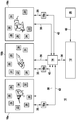
- the drawing shows a schematic view of an exemplary embodiment of a tool management system 10 according to the present invention.
- the tool management system comprises a central computer unit 12, a data transmission system 14, a plurality of user terminals 16a, 16b and 16c and a number of portable power tools 18a, 18b and 18c.
- the user terminals 16a, 16b and 16c are each smart cards carried by persons, which provide user data in the form of number codes which identify the users and are stored on them.
- the power tool 18a is a drilling machine
- 18b is a cut-off machine
- 18c is a jigsaw.
- the tool management system can have more than the tools and user terminals shown.
- Each power tool 18a, 18b, 18c comprises a data reception unit 20, a data processing unit 22, a storage unit 24, a device security device 26, a logging device 28, a position determination unit 30 and a unit 34 which realizes further functions, in particular software update, remote diagnosis and remote maintenance functions.
- the power tool 18a further comprises a battery monitoring unit 32.
- the data receiving units 20 are each designed such that they can receive the user data provided by the user terminals 16a, 16b and 16c as soon as one of the user terminals 16a, 16b and 16c is within transmission range, which is normally approximately 1 m.
- the user data are transmitted wirelessly from the user terminals 16a, 16b and 16c to the corresponding data reception unit 20, which is shown with the aid of the arrows 35, from there to the data processing unit 22 forwarded, which assigns the user data to one of a plurality of predefined user groups stored in the storage unit 24, which are characterized by different usage rights.
- the power tool can then be operated by the user within the scope of the assigned usage rights.
- a user can be granted unlimited, partially restricted or no usage rights.
- a restriction can be made, for example, with regard to the maximum power, speed, etc. of one of the power tools 18a, 18b or 18c.
- the data responsible for the assignment must be updated in the storage unit 24 of one or more of the tools 18a, 18b and 18c.
- the corresponding data sets are generated in the central computer unit 12 and sent via the data transmission system 14 to the corresponding tools 18a, 18b, 18c, which is indicated in the drawing by the arrows 36.
- the old data records are then correspondingly replaced in the storage unit (s) 24 by the new data records. In this way, the user data can be updated easily, quickly and inexpensively.
- the device securing devices 26 of each tool 18a, 18b and 18c each comprise at least one safety mechanism for averting dangerous operating situations when the corresponding tool 18a, 18b, 18c is used.
- the tool 18a comprises a safety mechanism which, via appropriate sensors, ensures that the drilling machine is gripped by the user with both hands. If this is not the case, the operation of the drill is automatically prevented.
- the tools 18b and 18c each comprise a safety mechanism that monitors the working environment in the area of the cutting tools with the aid of suitable sensors and ensures that no part of a person's body is in the working environment. If the sensors detect a part of a person's body, the corresponding tool 18b, 18c is automatically switched off.
- the device security device 26 of the jigsaw automatically generates an alarm signal which is transmitted to the central computer unit 12 via the data transmission system 14 (see arrows 36).
- the central computer unit 12 forwards the alarm signal to an ambulance service 38, which is indicated in the drawing by the arrow 40, which provides appropriate rescue workers in order to provide the injured user with medical care.
- the central computer unit 12 transmits the alarm signal to the tools 18a and 18b when they are in close proximity to the tool 18c. In this way, the users of the tools 18a and 18b are informed of the accident at the location of the tool 18c and can come to their help.
- a comprehensive accident management system is provided by the combination of the device securing devices 26, the data transmission system 14, the central computer unit 12 and the rescue service 38 described above.
- the device security devices 26 can also be updated in terms of data technology via the central computer unit 12 and the data transmission system 14.
- the position determination units 30 of each tool 18a, 18b and 18c each generate position signals at predetermined time intervals, for example via GPS, which are transmitted to the central computer unit 12 via the data transmission system 14. In this way, the respective positions of the tools 18a, 18b and 18c can always be determined, and even an unsuccessful user can be quickly located when the central computer unit 12 receives an alarm signal from one of the tools 18a, 18b or 18c.
- the tool management system 10 is set up such that an alarm signal is generated as soon as the position signals generated by a position determination unit 30 reach a position outside a predetermined position range Show.
- the predetermined position range is the company premises. Accordingly, an alarm signal is generated when one of the tools leaves the company premises, creating an anti-theft device.
- the position signals are stored in the logging device 28 together with the date and time.
- the chronological course of the tool location can be recorded in the form of a history.
- This history is then automatically transmitted at predetermined time intervals to a higher-level central unit, not shown, or is queried by such a central unit.
- This central unit which is located at the tool manufacturer, for example, collects and checks the histories of a large number of tool management systems 10 to determine whether there is a tool reported as stolen among the tools. If such a tool is found, its location can be communicated to the rightful owner.
- the battery monitoring unit 32 of the tool 18a monitors the charge status of the tool battery. If this is nearing the end, this is indicated to the user by a corresponding device provided on the tool 18a, so that the user can charge or replace the battery at an early stage. Furthermore, battery signals representing the battery charge state are transmitted to the central computer unit 12 via the data transmission system 14, which is also identified by the corresponding arrows 36. Accordingly, for example, personnel can be instructed to bring a new charged battery to the tool 18a.
- the further unit 34 represents further functions that can be integrated into the tool management system 10, such as, for example, a software update, remote maintenance or remote diagnosis function. Unit 34 can also communicate with central processing unit 14 via data transmission system 14.
- the logging device 28 is used to record a wide variety of data. For example, it can be logged which user used one of the tools 18a, 18b, 18c at which point in time, where which tool 18a, 18b, 18c was located, when and where and when one of the device security devices 26 generated an alarm signal, when one of the Device safety devices 26 has switched off the operation of one of the tools 18a, 18b, 18c, when and with which of the tools 18a, 18b, 18c data or software were changed or updated, when and which maintenance work on the tools 18a, 18b, 18c took place, etc.
- the logged data can be evaluated with the appropriate means in real time or at a later time.
Landscapes
- Business, Economics & Management (AREA)
- Physics & Mathematics (AREA)
- Engineering & Computer Science (AREA)
- General Physics & Mathematics (AREA)
- Emergency Management (AREA)
- Economics (AREA)
- General Health & Medical Sciences (AREA)
- Entrepreneurship & Innovation (AREA)
- Human Resources & Organizations (AREA)
- Strategic Management (AREA)
- Child & Adolescent Psychology (AREA)
- Health & Medical Sciences (AREA)
- Game Theory and Decision Science (AREA)
- Tourism & Hospitality (AREA)
- General Business, Economics & Management (AREA)
- Quality & Reliability (AREA)
- Theoretical Computer Science (AREA)
- Operations Research (AREA)
- Marketing (AREA)
- Educational Administration (AREA)
- Development Economics (AREA)
- Mechanical Engineering (AREA)
- Alarm Systems (AREA)
- Management, Administration, Business Operations System, And Electronic Commerce (AREA)
Claims (6)
- Système de gestion d'outils (10) destiné à coordonner et contrôler l'utilisation d'au moins une pluralité d'outils (18a, 18b, 18c), notamment d'outils électriques portables, le système de gestion d'outils (10) comportant un système de contrôle d'utilisateur comportant :• des terminaux d'utilisateur (16a, 16b, 16c) destinés à fournir des données d'utilisateur identifiant un utilisateur souhaitant utiliser un des outils (18a, 18b, 18c),• des unités de réception de données (20) prévues dans les outils (18a, 18b, 18c) et destinées à recevoir les données d'utilisateur fournies par les terminaux d'utilisateur (16a, 16b, 16c),• au moins une unité de traitement de données (22) conçue pour affecter les données d'utilisateur, reçues par l'une des unités de réception de données (20), à l'un d'une pluralité de groupes d'utilisateurs prédéfinis, qui sont enregistrés dans une unité de mémoire (24), avec des droits d'utilisation différents, et permettant la commande de l'outil (18a, 18b, 18c) correspondant, le système de gestion d'outils (10) comportant une unité centrale de calcul (12) et un système de transmission de données (14), et est conçu pour transmettre des données concernant au moins des utilisateurs et/ou des droits d'utilisation entre l'unité centrale de calcul (12) et les outils (18a, 18b, 18c) munis des unités de réception de données (20) et des données d'outils identifiant les outils (18a, 18b, 18c) par l'intermédiaire du système de transmission de données (14),caractérisé en ce que le système de gestion d'outils (10) comprend en outre :• des dispositifs de sécurisation d'appareils (26) prévus dans au moins certains des outils (18a, 18b, 18c), dans lequel les dispositifs de sécurisation d'appareils (26) comprennent respectivement un mécanisme de sécurité destiné à éviter des situations de commande dangereuses lors de l'utilisation de l'outil (18a, 18b, 18c) et sont conçus, lors d'un incident détecté à l'aide de capteurs, de manière à ce qu'ils génèrent un signal d'alarme et le transmettent à l'unité centrale de calcul (12) par l'intermédiaire du système de transmission de données (14), et le système de gestion d'outils (10) est conçu pour envoyer les signaux d'alarme par l'intermédiaire du système de transmission de données (14) à d'autres outils (18a, 18b, 18c) munis d'autres unités de réception de données (20).
- Système de gestion d'outils (10) selon la revendication 1, caractérisé en ce que des données d'outils identifiant des outils (18a, 18b, 18c) peuvent être transmises par les outils (18a, 18b, 18c) par l'intermédiaire du système de transmission de données (24) à l'unité centrale de calcul (12), et les outils (18a, 18b, 18c) sont affectés de manière univoque au système de gestion d'outils (10) par l'intermédiaire des données d'outils de manière à ce que des droits d'utilisation non restreints, partiellement restreints soient accordés ou qu'aucun droit d'utilisation ne soit accordé à un utilisateur en fonction du groupe d'utilisateurs, et en ce qu'un signal d'alarme est généré lorsque l'unité centrale de calcul (12) reçoit des données d'outils qui ne sont pas affectées au système de gestion d'outils (10).
- Système de gestion d'outils (10) selon la revendication 2, caractérisé en ce que les données d'outils sont transmises par les outils (18a, 18b, 18c) à l'unité centrale de calcul (12) par l'intermédiaire du système de transmission de données (14) à des intervalles de temps prédéterminés, et en ce qu'un signal d'alarme est généré lorsque les données d'outils d'un outil (18a, 18b, 18c) ne sont pas transmises à un instant prédéterminé.
- Système de gestion d'outils (10) selon la revendication 1, caractérisé en ce qu'il est conçu de manière à ce que les signaux d'alarme et/ou des signaux et/ou des données générés à partir de ceux-ci soient transmis à un service de secours (38).
- Système de gestion d'outils (10) selon l'une des revendications précédentes, caractérisé en ce qu'il comprend des unités de détermination de position (30) prévues sur au moins certains des outils (18a, 18b, 18c) pour déterminer des données de position des outils, dans lequel les unités de détermination de position (30) sont conçues pour générer des signaux de position qui peuvent être transmis à l'unité centrale de calcul (12) par l'intermédiaire du système de transmission de données (14) .
- Système de gestion d'outils (10) selon l'une des revendications précédentes, caractérisé en ce qu'il comporte des unités de mise à jour de logiciel pour la mise à jour du logiciel d'outil et/ou des unités de télémaintenance pour la télémaintenance d'outils et/ou des unités de diagnostic à distance pour le diagnostic d'états des outils, le système de gestion d'outils (10) étant conçu de manière à ce que des données relatives à la mise à jour du logiciel et/ou à la télémaintenance et/ou au diagnostic à distance puissent être transmises entre l'unité centrale de calcul et les outils correspondants par l'intermédiaire du système de transmission de données.
Applications Claiming Priority (2)
| Application Number | Priority Date | Filing Date | Title |
|---|---|---|---|
| DE102007035095A DE102007035095A1 (de) | 2007-07-26 | 2007-07-26 | Werkzeugmanagementsystem |
| PCT/EP2008/056525 WO2009013045A1 (fr) | 2007-07-26 | 2008-05-28 | Système de gestion d'outils |
Publications (2)
| Publication Number | Publication Date |
|---|---|
| EP2186064A1 EP2186064A1 (fr) | 2010-05-19 |
| EP2186064B1 true EP2186064B1 (fr) | 2020-01-01 |
Family
ID=39719106
Family Applications (1)
| Application Number | Title | Priority Date | Filing Date |
|---|---|---|---|
| EP08760121.7A Active EP2186064B1 (fr) | 2007-07-26 | 2008-05-28 | Système de gestion d'outils |
Country Status (3)
| Country | Link |
|---|---|
| EP (1) | EP2186064B1 (fr) |
| DE (1) | DE102007035095A1 (fr) |
| WO (1) | WO2009013045A1 (fr) |
Cited By (4)
| Publication number | Priority date | Publication date | Assignee | Title |
|---|---|---|---|---|
| WO2022033756A1 (fr) * | 2020-08-14 | 2022-02-17 | Robert Bosch Gmbh | Système et procédé d'identification de sources de danger et/ou plus particulièrement d'avertissement sélectif de sources de danger |
| US20240367303A1 (en) * | 2021-09-10 | 2024-11-07 | Milwaukee Electric Tool Corporation | Systems and Methods for Tool Location Tracking |
| US20240424655A1 (en) * | 2021-09-10 | 2024-12-26 | Milwaukee Electric Tool Corporation | Systems and Methods for Multi-Channel Power Tool Communication |
| US20250256385A1 (en) * | 2024-02-12 | 2025-08-14 | Black & Decker Inc. | Auxiliary wireless device for power tool |
Families Citing this family (27)
| Publication number | Priority date | Publication date | Assignee | Title |
|---|---|---|---|---|
| US8269612B2 (en) | 2008-07-10 | 2012-09-18 | Black & Decker Inc. | Communication protocol for remotely controlled laser devices |
| DE102011119489B4 (de) | 2010-11-30 | 2021-05-06 | Marquardt Verwaltungs-Gmbh | Elektrischer Schalter |
| US9467862B2 (en) | 2011-10-26 | 2016-10-11 | Milwaukee Electric Tool Corporation | Wireless tracking of power tools and related devices |
| DE102011089499A1 (de) * | 2011-12-21 | 2013-06-27 | Hilti Aktiengesellschaft | Kommunikationsvorrichtung und Verwendung einer Kommunikationsvorrichtung |
| DE102012200819A1 (de) * | 2012-01-20 | 2013-07-25 | Robert Bosch Gmbh | Verfahren mit einer Handwerkzeugmaschine und einem mobilen Computer |
| US9908182B2 (en) | 2012-01-30 | 2018-03-06 | Black & Decker Inc. | Remote programming of a power tool |
| WO2013134620A1 (fr) * | 2012-03-08 | 2013-09-12 | Husqvarna Ab | Système et procédé d'appariement opérateur-équipement automatisé |
| US10685299B2 (en) | 2012-03-08 | 2020-06-16 | Husqvarna Ab | Engine speed data usage system and method |
| US20130327552A1 (en) | 2012-06-08 | 2013-12-12 | Black & Decker Inc. | Power tool having multiple operating modes |
| US9256988B2 (en) | 2012-09-11 | 2016-02-09 | Black & Decker Inc. | System and method for identifying a power tool |
| US10158213B2 (en) | 2013-02-22 | 2018-12-18 | Milwaukee Electric Tool Corporation | Worksite power distribution box |
| US9466198B2 (en) | 2013-02-22 | 2016-10-11 | Milwaukee Electric Tool Corporation | Wireless tracking of power tools and related devices |
| DE102013212003A1 (de) | 2013-06-25 | 2015-01-08 | Robert Bosch Gmbh | Handwerkzeugmaschine |
| DE102014208980A1 (de) * | 2014-01-27 | 2015-07-30 | Robert Bosch Gmbh | Werkzeugmaschinenvorrichtung |
| DE102014209032A1 (de) | 2014-01-27 | 2015-07-30 | Robert Bosch Gmbh | Werkzeugmaschinenvorrichtung |
| DE102014209009A1 (de) * | 2014-01-27 | 2015-07-30 | Robert Bosch Gmbh | Werkzeugmaschinenvorrichtung |
| WO2015118900A1 (fr) * | 2014-02-04 | 2015-08-13 | 日立工機株式会社 | Système de notification de défaillance, outil électrique, et terminal de communication |
| SE1451280A1 (en) | 2014-10-24 | 2016-04-25 | Rsg Stockholm Ab | System and method for follow-up of a building or construction project |
| US9917457B2 (en) | 2015-02-02 | 2018-03-13 | Black & Decker Inc. | Power tool with USB connection |
| CN207096983U (zh) | 2015-06-16 | 2018-03-13 | 米沃奇电动工具公司 | 包括电动工具和外部设备的系统、包括外部设备和服务器的系统和服务器 |
| DE102016201497A1 (de) * | 2016-02-01 | 2017-08-03 | Robert Bosch Gmbh | Diebstahlschutzmodul für eine akkubetriebene Elektrowerkzeugmaschine und akkubetriebene Elektrowerkzeugmaschine mit einem Diebstahlschutzmodul |
| TWM555274U (zh) | 2016-06-06 | 2018-02-11 | 米沃奇電子工具公司 | 用以與動力工具裝置作連接的行動裝置 |
| US11622392B2 (en) | 2016-06-06 | 2023-04-04 | Milwaukee Electric Tool Corporation | System and method for establishing a wireless connection between power tool and mobile device |
| DE102017202286A1 (de) * | 2017-02-14 | 2018-08-16 | Robert Bosch Gmbh | Überwachung eines elektrischen Handwerkzeugs |
| DE102017206064A1 (de) * | 2017-04-10 | 2018-10-11 | Robert Bosch Gmbh | Handwerkzeugmaschine |
| DE102018203179A1 (de) * | 2018-03-02 | 2019-09-05 | Robert Bosch Gmbh | Vorrichtung, insbesondere Handwerkzeugmaschinen-Verwaltungsvorrichtung, und Verfahren zur Überwachung und/oder zur Verwaltung einer Vielzahl von Gegenständen |
| CN111080849A (zh) * | 2019-12-04 | 2020-04-28 | 珠海格力电器股份有限公司 | 刀具管理方法、刀具柜及存储介质 |
Citations (3)
| Publication number | Priority date | Publication date | Assignee | Title |
|---|---|---|---|---|
| GB2352057A (en) * | 1999-07-02 | 2001-01-17 | Addapac Ltd | Apparatus for controlling the availability of functions in a machine |
| GB2353180A (en) * | 1999-06-09 | 2001-02-14 | David George Watts | Automatic security system particularly for plant and machinery |
| WO2003038764A2 (fr) * | 2001-10-24 | 2003-05-08 | Siemens Aktiengesellschaft | Systeme de securite |
Family Cites Families (8)
| Publication number | Priority date | Publication date | Assignee | Title |
|---|---|---|---|---|
| IL93567A (en) * | 1990-02-27 | 1993-02-21 | Israel Hirshberg | Self renting car |
| US7613590B2 (en) | 1992-11-17 | 2009-11-03 | Health Hero Network, Inc. | Modular microprocessor-based power tool system |
| US6225890B1 (en) * | 1998-03-20 | 2001-05-01 | Trimble Navigation Limited | Vehicle use control |
| DE10232934A1 (de) | 2002-07-19 | 2004-01-29 | Ident Technology Ag | Handgriffeinrichtung sowie Sicherheitsschaltungsanordnung insbesondere für ein kraftbetriebenes Werkzeug |
| ES2280888T3 (es) * | 2003-11-24 | 2007-09-16 | Black & Decker Inc. | Sistema inalambrico para vigilancia y seguridad de bienes. |
| US7061366B2 (en) * | 2004-04-12 | 2006-06-13 | Microsoft Corporation | Finding location and ranging explorer |
| US7298240B2 (en) | 2004-09-24 | 2007-11-20 | David Lamar | Electronically enabling devices remotely |
| DE102005058993A1 (de) | 2004-12-09 | 2006-07-06 | Ident Technology Ag | Gerätesicherungssystem zum abgesicherten Betrieb von gefährdungsrelevanten Motorgeräten, insbesondere Gartengeräten und Werkzeugen |
-
2007
- 2007-07-26 DE DE102007035095A patent/DE102007035095A1/de not_active Withdrawn
-
2008
- 2008-05-28 WO PCT/EP2008/056525 patent/WO2009013045A1/fr not_active Ceased
- 2008-05-28 EP EP08760121.7A patent/EP2186064B1/fr active Active
Patent Citations (3)
| Publication number | Priority date | Publication date | Assignee | Title |
|---|---|---|---|---|
| GB2353180A (en) * | 1999-06-09 | 2001-02-14 | David George Watts | Automatic security system particularly for plant and machinery |
| GB2352057A (en) * | 1999-07-02 | 2001-01-17 | Addapac Ltd | Apparatus for controlling the availability of functions in a machine |
| WO2003038764A2 (fr) * | 2001-10-24 | 2003-05-08 | Siemens Aktiengesellschaft | Systeme de securite |
Cited By (4)
| Publication number | Priority date | Publication date | Assignee | Title |
|---|---|---|---|---|
| WO2022033756A1 (fr) * | 2020-08-14 | 2022-02-17 | Robert Bosch Gmbh | Système et procédé d'identification de sources de danger et/ou plus particulièrement d'avertissement sélectif de sources de danger |
| US20240367303A1 (en) * | 2021-09-10 | 2024-11-07 | Milwaukee Electric Tool Corporation | Systems and Methods for Tool Location Tracking |
| US20240424655A1 (en) * | 2021-09-10 | 2024-12-26 | Milwaukee Electric Tool Corporation | Systems and Methods for Multi-Channel Power Tool Communication |
| US20250256385A1 (en) * | 2024-02-12 | 2025-08-14 | Black & Decker Inc. | Auxiliary wireless device for power tool |
Also Published As
| Publication number | Publication date |
|---|---|
| WO2009013045A1 (fr) | 2009-01-29 |
| DE102007035095A1 (de) | 2009-01-29 |
| EP2186064A1 (fr) | 2010-05-19 |
Similar Documents
| Publication | Publication Date | Title |
|---|---|---|
| EP2186064A1 (fr) | Système de gestion d'outils | |
| EP3231198B1 (fr) | Système, notamment système de machine-outil à main | |
| WO2017108320A1 (fr) | Dispositif portable de contrôle de passage pour une zone de travail | |
| EP1866712A2 (fr) | Procedes et dispositifs permettant d'attribuer le commandement d'un operateur a un dispositif technique a commande de façon fiable, exclusive et sans confusion | |
| DE102015226198A1 (de) | Elektronische Autorisierungsvorrichtung | |
| DE102018200197A1 (de) | Elektrisch angetriebenes Werkzeug mit mindestens einem intelligenten Bremsaktuator und Verfahren zum Betreiben eines Werkzeugs | |
| EP2126525A1 (fr) | Dosimètre de vibrations pour la détermination de contraintes vibratoires | |
| EP3471922B1 (fr) | Procédé de blocage d'au moins une machine d'usinage, en particulier d'une machine-outil portative | |
| EP3878520B1 (fr) | Procédé de fonctionnement d'un système de sauvetage doté d'un appareil mobile de sauvetage | |
| AT523567B1 (de) | Mobiles Rettungsgerät, sowie computerimplementiertes Verfahren zur Diebstahlsicherung des mobilen Rettungsgerätes | |
| EP3759660B1 (fr) | Dispositif, en particulier dispositif de gestion de machines-outils portatives, et procédé de surveillance et/ou de gestion d'une pluralité d'objets | |
| EP1688899A2 (fr) | Procédé et dispositif destinés à la surveillance de personnes nécessitant une assistance | |
| WO2018149727A1 (fr) | Surveillance d'un outil à main électrique | |
| DE102019126208A1 (de) | Notfallsystem für ein Fahrzeug | |
| DE10152349B4 (de) | Sicherheitseinrichtung | |
| DE102016210766A1 (de) | Verfahren zu einer Ermittlung zumindest einer Schwingungsbelastung eines Bedieners einer Bearbeitungsmaschine | |
| EP3444790A1 (fr) | Agencement et procédé de fonctionnement à distance d'un dispositif | |
| DE102017206068A1 (de) | Handwerkzeugmaschine | |
| DE102013223577A1 (de) | Maschinenbedieneinheit | |
| WO2023094126A1 (fr) | Procédé de surveillance d'articles d'équipements au moyen d'un système de surveillance et système de surveillance | |
| DE102010012397A1 (de) | Verfahren zur Überwachung des Aufmerksamkeitszustandes eines Bedieners einer Produktionseinrichtung | |
| EP3261058B1 (fr) | Procédé de fonctionnement d'un système | |
| DE102016211097A1 (de) | Verfahren zu einem Betrieb eines Systems | |
| DE102016211351A1 (de) | Verfahren zu einer Überwachung und/oder zu einer Koordination einer Baustelle | |
| DE102012013870B4 (de) | Vorrichtung und Sicherungssystem für eine Handfeuerwaffe gegen unautorisierten Gebrauch, mit einem Waffenschloss |
Legal Events
| Date | Code | Title | Description |
|---|---|---|---|
| PUAI | Public reference made under article 153(3) epc to a published international application that has entered the european phase |
Free format text: ORIGINAL CODE: 0009012 |
|
| 17P | Request for examination filed |
Effective date: 20100226 |
|
| AK | Designated contracting states |
Kind code of ref document: A1 Designated state(s): AT BE BG CH CY CZ DE DK EE ES FI FR GB GR HR HU IE IS IT LI LT LU LV MC MT NL NO PL PT RO SE SI SK TR |
|
| AX | Request for extension of the european patent |
Extension state: AL BA MK RS |
|
| 17Q | First examination report despatched |
Effective date: 20100511 |
|
| DAX | Request for extension of the european patent (deleted) | ||
| STAA | Information on the status of an ep patent application or granted ep patent |
Free format text: STATUS: EXAMINATION IS IN PROGRESS |
|
| REG | Reference to a national code |
Ref country code: DE Ref legal event code: R079 Ref document number: 502008016998 Country of ref document: DE Free format text: PREVIOUS MAIN CLASS: G07C0009000000 Ipc: G08B0025010000 |
|
| RIC1 | Information provided on ipc code assigned before grant |
Ipc: G08B 27/00 20060101ALN20190529BHEP Ipc: G08B 25/01 20060101AFI20190529BHEP Ipc: B25F 5/00 20060101ALI20190529BHEP Ipc: G06Q 10/06 20120101ALI20190529BHEP |
|
| GRAP | Despatch of communication of intention to grant a patent |
Free format text: ORIGINAL CODE: EPIDOSNIGR1 |
|
| STAA | Information on the status of an ep patent application or granted ep patent |
Free format text: STATUS: GRANT OF PATENT IS INTENDED |
|
| RIC1 | Information provided on ipc code assigned before grant |
Ipc: B25F 5/00 20060101ALI20190702BHEP Ipc: G08B 27/00 20060101ALN20190702BHEP Ipc: G08B 25/01 20060101AFI20190702BHEP Ipc: G08B 13/14 20060101ALI20190702BHEP Ipc: G08B 21/02 20060101ALI20190702BHEP Ipc: G06Q 10/06 20120101ALI20190702BHEP |
|
| INTG | Intention to grant announced |
Effective date: 20190726 |
|
| GRAS | Grant fee paid |
Free format text: ORIGINAL CODE: EPIDOSNIGR3 |
|
| GRAA | (expected) grant |
Free format text: ORIGINAL CODE: 0009210 |
|
| STAA | Information on the status of an ep patent application or granted ep patent |
Free format text: STATUS: THE PATENT HAS BEEN GRANTED |
|
| AK | Designated contracting states |
Kind code of ref document: B1 Designated state(s): AT BE BG CH CY CZ DE DK EE ES FI FR GB GR HR HU IE IS IT LI LT LU LV MC MT NL NO PL PT RO SE SI SK TR |
|
| REG | Reference to a national code |
Ref country code: GB Ref legal event code: FG4D Free format text: NOT ENGLISH |
|
| REG | Reference to a national code |
Ref country code: AT Ref legal event code: REF Ref document number: 1220774 Country of ref document: AT Kind code of ref document: T Effective date: 20200115 Ref country code: CH Ref legal event code: EP |
|
| REG | Reference to a national code |
Ref country code: IE Ref legal event code: FG4D Free format text: LANGUAGE OF EP DOCUMENT: GERMAN |
|
| REG | Reference to a national code |
Ref country code: DE Ref legal event code: R096 Ref document number: 502008016998 Country of ref document: DE |
|
| RAP2 | Party data changed (patent owner data changed or rights of a patent transferred) |
Owner name: ROBERT BOSCH GMBH |
|
| REG | Reference to a national code |
Ref country code: NL Ref legal event code: MP Effective date: 20200101 |
|
| REG | Reference to a national code |
Ref country code: LT Ref legal event code: MG4D |
|
| PG25 | Lapsed in a contracting state [announced via postgrant information from national office to epo] |
Ref country code: LT Free format text: LAPSE BECAUSE OF FAILURE TO SUBMIT A TRANSLATION OF THE DESCRIPTION OR TO PAY THE FEE WITHIN THE PRESCRIBED TIME-LIMIT Effective date: 20200101 Ref country code: CZ Free format text: LAPSE BECAUSE OF FAILURE TO SUBMIT A TRANSLATION OF THE DESCRIPTION OR TO PAY THE FEE WITHIN THE PRESCRIBED TIME-LIMIT Effective date: 20200101 Ref country code: PT Free format text: LAPSE BECAUSE OF FAILURE TO SUBMIT A TRANSLATION OF THE DESCRIPTION OR TO PAY THE FEE WITHIN THE PRESCRIBED TIME-LIMIT Effective date: 20200527 Ref country code: FI Free format text: LAPSE BECAUSE OF FAILURE TO SUBMIT A TRANSLATION OF THE DESCRIPTION OR TO PAY THE FEE WITHIN THE PRESCRIBED TIME-LIMIT Effective date: 20200101 Ref country code: NO Free format text: LAPSE BECAUSE OF FAILURE TO SUBMIT A TRANSLATION OF THE DESCRIPTION OR TO PAY THE FEE WITHIN THE PRESCRIBED TIME-LIMIT Effective date: 20200401 Ref country code: NL Free format text: LAPSE BECAUSE OF FAILURE TO SUBMIT A TRANSLATION OF THE DESCRIPTION OR TO PAY THE FEE WITHIN THE PRESCRIBED TIME-LIMIT Effective date: 20200101 |
|
| PG25 | Lapsed in a contracting state [announced via postgrant information from national office to epo] |
Ref country code: HR Free format text: LAPSE BECAUSE OF FAILURE TO SUBMIT A TRANSLATION OF THE DESCRIPTION OR TO PAY THE FEE WITHIN THE PRESCRIBED TIME-LIMIT Effective date: 20200101 Ref country code: LV Free format text: LAPSE BECAUSE OF FAILURE TO SUBMIT A TRANSLATION OF THE DESCRIPTION OR TO PAY THE FEE WITHIN THE PRESCRIBED TIME-LIMIT Effective date: 20200101 Ref country code: IS Free format text: LAPSE BECAUSE OF FAILURE TO SUBMIT A TRANSLATION OF THE DESCRIPTION OR TO PAY THE FEE WITHIN THE PRESCRIBED TIME-LIMIT Effective date: 20200501 Ref country code: SE Free format text: LAPSE BECAUSE OF FAILURE TO SUBMIT A TRANSLATION OF THE DESCRIPTION OR TO PAY THE FEE WITHIN THE PRESCRIBED TIME-LIMIT Effective date: 20200101 Ref country code: BG Free format text: LAPSE BECAUSE OF FAILURE TO SUBMIT A TRANSLATION OF THE DESCRIPTION OR TO PAY THE FEE WITHIN THE PRESCRIBED TIME-LIMIT Effective date: 20200401 Ref country code: GR Free format text: LAPSE BECAUSE OF FAILURE TO SUBMIT A TRANSLATION OF THE DESCRIPTION OR TO PAY THE FEE WITHIN THE PRESCRIBED TIME-LIMIT Effective date: 20200402 |
|
| REG | Reference to a national code |
Ref country code: DE Ref legal event code: R097 Ref document number: 502008016998 Country of ref document: DE |
|
| PG25 | Lapsed in a contracting state [announced via postgrant information from national office to epo] |
Ref country code: ES Free format text: LAPSE BECAUSE OF FAILURE TO SUBMIT A TRANSLATION OF THE DESCRIPTION OR TO PAY THE FEE WITHIN THE PRESCRIBED TIME-LIMIT Effective date: 20200101 Ref country code: RO Free format text: LAPSE BECAUSE OF FAILURE TO SUBMIT A TRANSLATION OF THE DESCRIPTION OR TO PAY THE FEE WITHIN THE PRESCRIBED TIME-LIMIT Effective date: 20200101 Ref country code: SK Free format text: LAPSE BECAUSE OF FAILURE TO SUBMIT A TRANSLATION OF THE DESCRIPTION OR TO PAY THE FEE WITHIN THE PRESCRIBED TIME-LIMIT Effective date: 20200101 Ref country code: DK Free format text: LAPSE BECAUSE OF FAILURE TO SUBMIT A TRANSLATION OF THE DESCRIPTION OR TO PAY THE FEE WITHIN THE PRESCRIBED TIME-LIMIT Effective date: 20200101 Ref country code: EE Free format text: LAPSE BECAUSE OF FAILURE TO SUBMIT A TRANSLATION OF THE DESCRIPTION OR TO PAY THE FEE WITHIN THE PRESCRIBED TIME-LIMIT Effective date: 20200101 |
|
| PLBE | No opposition filed within time limit |
Free format text: ORIGINAL CODE: 0009261 |
|
| STAA | Information on the status of an ep patent application or granted ep patent |
Free format text: STATUS: NO OPPOSITION FILED WITHIN TIME LIMIT |
|
| 26N | No opposition filed |
Effective date: 20201002 |
|
| PG25 | Lapsed in a contracting state [announced via postgrant information from national office to epo] |
Ref country code: LI Free format text: LAPSE BECAUSE OF NON-PAYMENT OF DUE FEES Effective date: 20200531 Ref country code: CH Free format text: LAPSE BECAUSE OF NON-PAYMENT OF DUE FEES Effective date: 20200531 Ref country code: IT Free format text: LAPSE BECAUSE OF FAILURE TO SUBMIT A TRANSLATION OF THE DESCRIPTION OR TO PAY THE FEE WITHIN THE PRESCRIBED TIME-LIMIT Effective date: 20200101 Ref country code: MC Free format text: LAPSE BECAUSE OF FAILURE TO SUBMIT A TRANSLATION OF THE DESCRIPTION OR TO PAY THE FEE WITHIN THE PRESCRIBED TIME-LIMIT Effective date: 20200101 |
|
| PG25 | Lapsed in a contracting state [announced via postgrant information from national office to epo] |
Ref country code: PL Free format text: LAPSE BECAUSE OF FAILURE TO SUBMIT A TRANSLATION OF THE DESCRIPTION OR TO PAY THE FEE WITHIN THE PRESCRIBED TIME-LIMIT Effective date: 20200101 Ref country code: SI Free format text: LAPSE BECAUSE OF FAILURE TO SUBMIT A TRANSLATION OF THE DESCRIPTION OR TO PAY THE FEE WITHIN THE PRESCRIBED TIME-LIMIT Effective date: 20200101 |
|
| REG | Reference to a national code |
Ref country code: BE Ref legal event code: MM Effective date: 20200531 |
|
| PG25 | Lapsed in a contracting state [announced via postgrant information from national office to epo] |
Ref country code: LU Free format text: LAPSE BECAUSE OF NON-PAYMENT OF DUE FEES Effective date: 20200528 |
|
| PG25 | Lapsed in a contracting state [announced via postgrant information from national office to epo] |
Ref country code: IE Free format text: LAPSE BECAUSE OF NON-PAYMENT OF DUE FEES Effective date: 20200528 |
|
| PG25 | Lapsed in a contracting state [announced via postgrant information from national office to epo] |
Ref country code: BE Free format text: LAPSE BECAUSE OF NON-PAYMENT OF DUE FEES Effective date: 20200531 |
|
| REG | Reference to a national code |
Ref country code: AT Ref legal event code: MM01 Ref document number: 1220774 Country of ref document: AT Kind code of ref document: T Effective date: 20200528 |
|
| PGFP | Annual fee paid to national office [announced via postgrant information from national office to epo] |
Ref country code: FR Payment date: 20210525 Year of fee payment: 14 |
|
| PG25 | Lapsed in a contracting state [announced via postgrant information from national office to epo] |
Ref country code: AT Free format text: LAPSE BECAUSE OF NON-PAYMENT OF DUE FEES Effective date: 20200528 |
|
| PG25 | Lapsed in a contracting state [announced via postgrant information from national office to epo] |
Ref country code: TR Free format text: LAPSE BECAUSE OF FAILURE TO SUBMIT A TRANSLATION OF THE DESCRIPTION OR TO PAY THE FEE WITHIN THE PRESCRIBED TIME-LIMIT Effective date: 20200101 Ref country code: MT Free format text: LAPSE BECAUSE OF FAILURE TO SUBMIT A TRANSLATION OF THE DESCRIPTION OR TO PAY THE FEE WITHIN THE PRESCRIBED TIME-LIMIT Effective date: 20200101 Ref country code: CY Free format text: LAPSE BECAUSE OF FAILURE TO SUBMIT A TRANSLATION OF THE DESCRIPTION OR TO PAY THE FEE WITHIN THE PRESCRIBED TIME-LIMIT Effective date: 20200101 |
|
| PG25 | Lapsed in a contracting state [announced via postgrant information from national office to epo] |
Ref country code: FR Free format text: LAPSE BECAUSE OF NON-PAYMENT OF DUE FEES Effective date: 20220531 |
|
| PGFP | Annual fee paid to national office [announced via postgrant information from national office to epo] |
Ref country code: GB Payment date: 20230522 Year of fee payment: 16 |
|
| PGFP | Annual fee paid to national office [announced via postgrant information from national office to epo] |
Ref country code: DE Payment date: 20230726 Year of fee payment: 16 |
|
| REG | Reference to a national code |
Ref country code: DE Ref legal event code: R119 Ref document number: 502008016998 Country of ref document: DE |
|
| GBPC | Gb: european patent ceased through non-payment of renewal fee |
Effective date: 20240528 |
|
| PG25 | Lapsed in a contracting state [announced via postgrant information from national office to epo] |
Ref country code: DE Free format text: LAPSE BECAUSE OF NON-PAYMENT OF DUE FEES Effective date: 20241203 |
|
| PG25 | Lapsed in a contracting state [announced via postgrant information from national office to epo] |
Ref country code: GB Free format text: LAPSE BECAUSE OF NON-PAYMENT OF DUE FEES Effective date: 20240528 |