EP2186149B1 - Vliesstoff mit partikelfüllung - Google Patents
Vliesstoff mit partikelfüllung Download PDFInfo
- Publication number
- EP2186149B1 EP2186149B1 EP08784516A EP08784516A EP2186149B1 EP 2186149 B1 EP2186149 B1 EP 2186149B1 EP 08784516 A EP08784516 A EP 08784516A EP 08784516 A EP08784516 A EP 08784516A EP 2186149 B1 EP2186149 B1 EP 2186149B1
- Authority
- EP
- European Patent Office
- Prior art keywords
- particles
- pores
- ply according
- fibres
- fibers
- Prior art date
- Legal status (The legal status is an assumption and is not a legal conclusion. Google has not performed a legal analysis and makes no representation as to the accuracy of the status listed.)
- Not-in-force
Links
- 239000002245 particle Substances 0.000 title claims abstract description 78
- 239000000463 material Substances 0.000 title description 9
- 239000011148 porous material Substances 0.000 claims abstract description 66
- -1 polypropylene Polymers 0.000 claims abstract description 25
- 238000002844 melting Methods 0.000 claims abstract description 18
- 230000008018 melting Effects 0.000 claims abstract description 17
- 239000011230 binding agent Substances 0.000 claims abstract description 15
- 229920000620 organic polymer Polymers 0.000 claims abstract description 12
- 229920000036 polyvinylpyrrolidone Polymers 0.000 claims abstract description 11
- 239000001267 polyvinylpyrrolidone Substances 0.000 claims abstract description 11
- 235000013855 polyvinylpyrrolidone Nutrition 0.000 claims abstract description 11
- 239000004743 Polypropylene Substances 0.000 claims abstract description 9
- 239000011248 coating agent Substances 0.000 claims abstract description 9
- 238000000576 coating method Methods 0.000 claims abstract description 9
- 229920001155 polypropylene Polymers 0.000 claims abstract description 9
- 239000002033 PVDF binder Substances 0.000 claims abstract description 7
- 229920000058 polyacrylate Polymers 0.000 claims abstract description 7
- 229920000728 polyester Polymers 0.000 claims abstract description 7
- 229920002981 polyvinylidene fluoride Polymers 0.000 claims abstract description 7
- 229920000459 Nitrile rubber Polymers 0.000 claims abstract description 6
- 239000004793 Polystyrene Substances 0.000 claims abstract description 6
- 229920001577 copolymer Polymers 0.000 claims abstract description 6
- 229920002223 polystyrene Polymers 0.000 claims abstract description 6
- 229920003048 styrene butadiene rubber Polymers 0.000 claims abstract description 6
- 238000003490 calendering Methods 0.000 claims abstract description 5
- 229920000877 Melamine resin Polymers 0.000 claims abstract description 3
- 229930040373 Paraformaldehyde Natural products 0.000 claims abstract description 3
- 239000004696 Poly ether ether ketone Substances 0.000 claims abstract description 3
- 229920002845 Poly(methacrylic acid) Polymers 0.000 claims abstract description 3
- 239000004952 Polyamide Substances 0.000 claims abstract description 3
- 239000004642 Polyimide Substances 0.000 claims abstract description 3
- 239000004372 Polyvinyl alcohol Substances 0.000 claims abstract description 3
- 229920002125 Sokalan® Polymers 0.000 claims abstract description 3
- 229920002678 cellulose Polymers 0.000 claims abstract description 3
- 229920000126 latex Polymers 0.000 claims abstract description 3
- 239000004816 latex Substances 0.000 claims abstract description 3
- 229920001568 phenolic resin Polymers 0.000 claims abstract description 3
- 239000005011 phenolic resin Substances 0.000 claims abstract description 3
- 229920003207 poly(ethylene-2,6-naphthalate) Polymers 0.000 claims abstract description 3
- 229920002492 poly(sulfone) Polymers 0.000 claims abstract description 3
- 229920002401 polyacrylamide Polymers 0.000 claims abstract description 3
- 239000004584 polyacrylic acid Substances 0.000 claims abstract description 3
- 229920002239 polyacrylonitrile Polymers 0.000 claims abstract description 3
- 229920002647 polyamide Polymers 0.000 claims abstract description 3
- 229920000570 polyether Polymers 0.000 claims abstract description 3
- 229920002530 polyetherether ketone Polymers 0.000 claims abstract description 3
- 239000011112 polyethylene naphthalate Substances 0.000 claims abstract description 3
- 229920000139 polyethylene terephthalate Polymers 0.000 claims abstract description 3
- 239000005020 polyethylene terephthalate Substances 0.000 claims abstract description 3
- 229920001721 polyimide Polymers 0.000 claims abstract description 3
- 229920000193 polymethacrylate Polymers 0.000 claims abstract description 3
- 229920006324 polyoxymethylene Polymers 0.000 claims abstract description 3
- 229920002635 polyurethane Polymers 0.000 claims abstract description 3
- 239000004814 polyurethane Substances 0.000 claims abstract description 3
- 229920002689 polyvinyl acetate Polymers 0.000 claims abstract description 3
- 239000011118 polyvinyl acetate Substances 0.000 claims abstract description 3
- 229920002451 polyvinyl alcohol Polymers 0.000 claims abstract description 3
- 229920002587 poly(1,3-butadiene) polymer Polymers 0.000 claims abstract 3
- KXGFMDJXCMQABM-UHFFFAOYSA-N 2-methoxy-6-methylphenol Chemical compound [CH]OC1=CC=CC([CH])=C1O KXGFMDJXCMQABM-UHFFFAOYSA-N 0.000 claims abstract 2
- 239000004640 Melamine resin Substances 0.000 claims abstract 2
- 239000004744 fabric Substances 0.000 claims description 8
- 229920000642 polymer Polymers 0.000 claims description 5
- 238000009826 distribution Methods 0.000 claims description 4
- 239000000203 mixture Substances 0.000 claims description 3
- 239000001913 cellulose Substances 0.000 claims description 2
- 229920001707 polybutylene terephthalate Polymers 0.000 claims 1
- 239000000835 fiber Substances 0.000 abstract description 22
- KKEYFWRCBNTPAC-UHFFFAOYSA-L terephthalate(2-) Chemical compound [O-]C(=O)C1=CC=C(C([O-])=O)C=C1 KKEYFWRCBNTPAC-UHFFFAOYSA-L 0.000 abstract description 2
- 150000002825 nitriles Chemical class 0.000 abstract 2
- 239000004721 Polyphenylene oxide Substances 0.000 abstract 1
- 235000010980 cellulose Nutrition 0.000 abstract 1
- 239000012798 spherical particle Substances 0.000 abstract 1
- 239000004745 nonwoven fabric Substances 0.000 description 22
- 239000003990 capacitor Substances 0.000 description 9
- 238000012856 packing Methods 0.000 description 9
- 229910052751 metal Inorganic materials 0.000 description 8
- 239000002184 metal Substances 0.000 description 8
- 210000001787 dendrite Anatomy 0.000 description 7
- 238000005299 abrasion Methods 0.000 description 5
- 239000003792 electrolyte Substances 0.000 description 5
- 239000012528 membrane Substances 0.000 description 5
- 239000000919 ceramic Substances 0.000 description 4
- 230000000694 effects Effects 0.000 description 4
- 230000012010 growth Effects 0.000 description 4
- 239000010954 inorganic particle Substances 0.000 description 4
- 238000001878 scanning electron micrograph Methods 0.000 description 4
- 239000004698 Polyethylene Substances 0.000 description 3
- 230000015572 biosynthetic process Effects 0.000 description 3
- 229910001416 lithium ion Inorganic materials 0.000 description 3
- 238000004519 manufacturing process Methods 0.000 description 3
- 229920000573 polyethylene Polymers 0.000 description 3
- 229920000098 polyolefin Polymers 0.000 description 3
- XEEYBQQBJWHFJM-UHFFFAOYSA-N Iron Chemical compound [Fe] XEEYBQQBJWHFJM-UHFFFAOYSA-N 0.000 description 2
- WHXSMMKQMYFTQS-UHFFFAOYSA-N Lithium Chemical compound [Li] WHXSMMKQMYFTQS-UHFFFAOYSA-N 0.000 description 2
- HBBGRARXTFLTSG-UHFFFAOYSA-N Lithium ion Chemical compound [Li+] HBBGRARXTFLTSG-UHFFFAOYSA-N 0.000 description 2
- 210000004027 cell Anatomy 0.000 description 2
- 238000005524 ceramic coating Methods 0.000 description 2
- 238000011161 development Methods 0.000 description 2
- 230000018109 developmental process Effects 0.000 description 2
- 238000004146 energy storage Methods 0.000 description 2
- 239000000446 fuel Substances 0.000 description 2
- 239000007789 gas Substances 0.000 description 2
- 238000010438 heat treatment Methods 0.000 description 2
- 239000012535 impurity Substances 0.000 description 2
- 229910052744 lithium Inorganic materials 0.000 description 2
- 229920005989 resin Polymers 0.000 description 2
- 239000011347 resin Substances 0.000 description 2
- 239000002904 solvent Substances 0.000 description 2
- 125000006850 spacer group Chemical group 0.000 description 2
- 229920001169 thermoplastic Polymers 0.000 description 2
- 239000004416 thermosoftening plastic Substances 0.000 description 2
- PWHULOQIROXLJO-UHFFFAOYSA-N Manganese Chemical compound [Mn] PWHULOQIROXLJO-UHFFFAOYSA-N 0.000 description 1
- BPQQTUXANYXVAA-UHFFFAOYSA-N Orthosilicate Chemical compound [O-][Si]([O-])([O-])[O-] BPQQTUXANYXVAA-UHFFFAOYSA-N 0.000 description 1
- VYPSYNLAJGMNEJ-UHFFFAOYSA-N Silicium dioxide Chemical compound O=[Si]=O VYPSYNLAJGMNEJ-UHFFFAOYSA-N 0.000 description 1
- QCWXUUIWCKQGHC-UHFFFAOYSA-N Zirconium Chemical compound [Zr] QCWXUUIWCKQGHC-UHFFFAOYSA-N 0.000 description 1
- 239000002318 adhesion promoter Substances 0.000 description 1
- 229910052782 aluminium Inorganic materials 0.000 description 1
- XAGFODPZIPBFFR-UHFFFAOYSA-N aluminium Chemical compound [Al] XAGFODPZIPBFFR-UHFFFAOYSA-N 0.000 description 1
- 239000002800 charge carrier Substances 0.000 description 1
- 239000004020 conductor Substances 0.000 description 1
- 238000010276 construction Methods 0.000 description 1
- 239000011258 core-shell material Substances 0.000 description 1
- 238000005520 cutting process Methods 0.000 description 1
- 238000009792 diffusion process Methods 0.000 description 1
- 238000007599 discharging Methods 0.000 description 1
- 239000007772 electrode material Substances 0.000 description 1
- 230000002349 favourable effect Effects 0.000 description 1
- 239000000945 filler Substances 0.000 description 1
- 229920002313 fluoropolymer Polymers 0.000 description 1
- 230000004927 fusion Effects 0.000 description 1
- 239000003365 glass fiber Substances 0.000 description 1
- 150000002500 ions Chemical class 0.000 description 1
- 229910052742 iron Inorganic materials 0.000 description 1
- 239000007788 liquid Substances 0.000 description 1
- 229910052748 manganese Inorganic materials 0.000 description 1
- 239000011572 manganese Substances 0.000 description 1
- 239000000155 melt Substances 0.000 description 1
- 229910021645 metal ion Inorganic materials 0.000 description 1
- 150000002739 metals Chemical class 0.000 description 1
- 229920005594 polymer fiber Polymers 0.000 description 1
- 238000002360 preparation method Methods 0.000 description 1
- 229910052710 silicon Inorganic materials 0.000 description 1
- 239000010703 silicon Substances 0.000 description 1
- 239000002002 slurry Substances 0.000 description 1
- 238000003860 storage Methods 0.000 description 1
- 230000001629 suppression Effects 0.000 description 1
- 230000003746 surface roughness Effects 0.000 description 1
- 229920001187 thermosetting polymer Polymers 0.000 description 1
- 239000010409 thin film Substances 0.000 description 1
- 229920002554 vinyl polymer Polymers 0.000 description 1
- 239000001993 wax Substances 0.000 description 1
- 238000009736 wetting Methods 0.000 description 1
- 229910052726 zirconium Inorganic materials 0.000 description 1
Images


Classifications
-
- H—ELECTRICITY
- H01—ELECTRIC ELEMENTS
- H01M—PROCESSES OR MEANS, e.g. BATTERIES, FOR THE DIRECT CONVERSION OF CHEMICAL ENERGY INTO ELECTRICAL ENERGY
- H01M50/00—Constructional details or processes of manufacture of the non-active parts of electrochemical cells other than fuel cells, e.g. hybrid cells
- H01M50/40—Separators; Membranes; Diaphragms; Spacing elements inside cells
- H01M50/409—Separators, membranes or diaphragms characterised by the material
- H01M50/44—Fibrous material
-
- H—ELECTRICITY
- H01—ELECTRIC ELEMENTS
- H01G—CAPACITORS; CAPACITORS, RECTIFIERS, DETECTORS, SWITCHING DEVICES, LIGHT-SENSITIVE OR TEMPERATURE-SENSITIVE DEVICES OF THE ELECTROLYTIC TYPE
- H01G9/00—Electrolytic capacitors, rectifiers, detectors, switching devices, light-sensitive or temperature-sensitive devices; Processes of their manufacture
- H01G9/004—Details
- H01G9/02—Diaphragms; Separators
-
- H—ELECTRICITY
- H01—ELECTRIC ELEMENTS
- H01M—PROCESSES OR MEANS, e.g. BATTERIES, FOR THE DIRECT CONVERSION OF CHEMICAL ENERGY INTO ELECTRICAL ENERGY
- H01M50/00—Constructional details or processes of manufacture of the non-active parts of electrochemical cells other than fuel cells, e.g. hybrid cells
- H01M50/40—Separators; Membranes; Diaphragms; Spacing elements inside cells
- H01M50/409—Separators, membranes or diaphragms characterised by the material
- H01M50/411—Organic material
- H01M50/414—Synthetic resins, e.g. thermoplastics or thermosetting resins
-
- H—ELECTRICITY
- H01—ELECTRIC ELEMENTS
- H01M—PROCESSES OR MEANS, e.g. BATTERIES, FOR THE DIRECT CONVERSION OF CHEMICAL ENERGY INTO ELECTRICAL ENERGY
- H01M50/00—Constructional details or processes of manufacture of the non-active parts of electrochemical cells other than fuel cells, e.g. hybrid cells
- H01M50/40—Separators; Membranes; Diaphragms; Spacing elements inside cells
- H01M50/489—Separators, membranes, diaphragms or spacing elements inside the cells, characterised by their physical properties, e.g. swelling degree, hydrophilicity or shut down properties
- H01M50/491—Porosity
-
- H—ELECTRICITY
- H01—ELECTRIC ELEMENTS
- H01M—PROCESSES OR MEANS, e.g. BATTERIES, FOR THE DIRECT CONVERSION OF CHEMICAL ENERGY INTO ELECTRICAL ENERGY
- H01M50/00—Constructional details or processes of manufacture of the non-active parts of electrochemical cells other than fuel cells, e.g. hybrid cells
- H01M50/40—Separators; Membranes; Diaphragms; Spacing elements inside cells
- H01M50/489—Separators, membranes, diaphragms or spacing elements inside the cells, characterised by their physical properties, e.g. swelling degree, hydrophilicity or shut down properties
- H01M50/494—Tensile strength
-
- H—ELECTRICITY
- H01—ELECTRIC ELEMENTS
- H01M—PROCESSES OR MEANS, e.g. BATTERIES, FOR THE DIRECT CONVERSION OF CHEMICAL ENERGY INTO ELECTRICAL ENERGY
- H01M8/00—Fuel cells; Manufacture thereof
- H01M8/10—Fuel cells with solid electrolytes
- H01M2008/1095—Fuel cells with polymeric electrolytes
-
- Y—GENERAL TAGGING OF NEW TECHNOLOGICAL DEVELOPMENTS; GENERAL TAGGING OF CROSS-SECTIONAL TECHNOLOGIES SPANNING OVER SEVERAL SECTIONS OF THE IPC; TECHNICAL SUBJECTS COVERED BY FORMER USPC CROSS-REFERENCE ART COLLECTIONS [XRACs] AND DIGESTS
- Y02—TECHNOLOGIES OR APPLICATIONS FOR MITIGATION OR ADAPTATION AGAINST CLIMATE CHANGE
- Y02E—REDUCTION OF GREENHOUSE GAS [GHG] EMISSIONS, RELATED TO ENERGY GENERATION, TRANSMISSION OR DISTRIBUTION
- Y02E60/00—Enabling technologies; Technologies with a potential or indirect contribution to GHG emissions mitigation
- Y02E60/10—Energy storage using batteries
-
- Y—GENERAL TAGGING OF NEW TECHNOLOGICAL DEVELOPMENTS; GENERAL TAGGING OF CROSS-SECTIONAL TECHNOLOGIES SPANNING OVER SEVERAL SECTIONS OF THE IPC; TECHNICAL SUBJECTS COVERED BY FORMER USPC CROSS-REFERENCE ART COLLECTIONS [XRACs] AND DIGESTS
- Y02—TECHNOLOGIES OR APPLICATIONS FOR MITIGATION OR ADAPTATION AGAINST CLIMATE CHANGE
- Y02E—REDUCTION OF GREENHOUSE GAS [GHG] EMISSIONS, RELATED TO ENERGY GENERATION, TRANSMISSION OR DISTRIBUTION
- Y02E60/00—Enabling technologies; Technologies with a potential or indirect contribution to GHG emissions mitigation
- Y02E60/30—Hydrogen technology
- Y02E60/50—Fuel cells
-
- Y—GENERAL TAGGING OF NEW TECHNOLOGICAL DEVELOPMENTS; GENERAL TAGGING OF CROSS-SECTIONAL TECHNOLOGIES SPANNING OVER SEVERAL SECTIONS OF THE IPC; TECHNICAL SUBJECTS COVERED BY FORMER USPC CROSS-REFERENCE ART COLLECTIONS [XRACs] AND DIGESTS
- Y10—TECHNICAL SUBJECTS COVERED BY FORMER USPC
- Y10T—TECHNICAL SUBJECTS COVERED BY FORMER US CLASSIFICATION
- Y10T442/00—Fabric [woven, knitted, or nonwoven textile or cloth, etc.]
- Y10T442/20—Coated or impregnated woven, knit, or nonwoven fabric which is not [a] associated with another preformed layer or fiber layer or, [b] with respect to woven and knit, characterized, respectively, by a particular or differential weave or knit, wherein the coating or impregnation is neither a foamed material nor a free metal or alloy layer
- Y10T442/2008—Fabric composed of a fiber or strand which is of specific structural definition
-
- Y—GENERAL TAGGING OF NEW TECHNOLOGICAL DEVELOPMENTS; GENERAL TAGGING OF CROSS-SECTIONAL TECHNOLOGIES SPANNING OVER SEVERAL SECTIONS OF THE IPC; TECHNICAL SUBJECTS COVERED BY FORMER USPC CROSS-REFERENCE ART COLLECTIONS [XRACs] AND DIGESTS
- Y10—TECHNICAL SUBJECTS COVERED BY FORMER USPC
- Y10T—TECHNICAL SUBJECTS COVERED BY FORMER US CLASSIFICATION
- Y10T442/00—Fabric [woven, knitted, or nonwoven textile or cloth, etc.]
- Y10T442/20—Coated or impregnated woven, knit, or nonwoven fabric which is not [a] associated with another preformed layer or fiber layer or, [b] with respect to woven and knit, characterized, respectively, by a particular or differential weave or knit, wherein the coating or impregnation is neither a foamed material nor a free metal or alloy layer
- Y10T442/2861—Coated or impregnated synthetic organic fiber fabric
- Y10T442/2885—Coated or impregnated acrylic fiber fabric
-
- Y—GENERAL TAGGING OF NEW TECHNOLOGICAL DEVELOPMENTS; GENERAL TAGGING OF CROSS-SECTIONAL TECHNOLOGIES SPANNING OVER SEVERAL SECTIONS OF THE IPC; TECHNICAL SUBJECTS COVERED BY FORMER USPC CROSS-REFERENCE ART COLLECTIONS [XRACs] AND DIGESTS
- Y10—TECHNICAL SUBJECTS COVERED BY FORMER USPC
- Y10T—TECHNICAL SUBJECTS COVERED BY FORMER US CLASSIFICATION
- Y10T442/00—Fabric [woven, knitted, or nonwoven textile or cloth, etc.]
- Y10T442/20—Coated or impregnated woven, knit, or nonwoven fabric which is not [a] associated with another preformed layer or fiber layer or, [b] with respect to woven and knit, characterized, respectively, by a particular or differential weave or knit, wherein the coating or impregnation is neither a foamed material nor a free metal or alloy layer
- Y10T442/2861—Coated or impregnated synthetic organic fiber fabric
- Y10T442/2893—Coated or impregnated polyamide fiber fabric
-
- Y—GENERAL TAGGING OF NEW TECHNOLOGICAL DEVELOPMENTS; GENERAL TAGGING OF CROSS-SECTIONAL TECHNOLOGIES SPANNING OVER SEVERAL SECTIONS OF THE IPC; TECHNICAL SUBJECTS COVERED BY FORMER USPC CROSS-REFERENCE ART COLLECTIONS [XRACs] AND DIGESTS
- Y10—TECHNICAL SUBJECTS COVERED BY FORMER USPC
- Y10T—TECHNICAL SUBJECTS COVERED BY FORMER US CLASSIFICATION
- Y10T442/00—Fabric [woven, knitted, or nonwoven textile or cloth, etc.]
- Y10T442/20—Coated or impregnated woven, knit, or nonwoven fabric which is not [a] associated with another preformed layer or fiber layer or, [b] with respect to woven and knit, characterized, respectively, by a particular or differential weave or knit, wherein the coating or impregnation is neither a foamed material nor a free metal or alloy layer
- Y10T442/2861—Coated or impregnated synthetic organic fiber fabric
- Y10T442/291—Coated or impregnated polyolefin fiber fabric
- Y10T442/2918—Polypropylene fiber fabric
Definitions
- the invention relates to a layer according to the preamble of patent claim 1.
- From the DE 102 38 944 A1 is a layer of a non-woven of polymer fibers known, which has a ceramic coating.
- a layer is known in which a porous body is provided at least on one side with a resin coating
- WO 2006/062153 A1 discloses a porous body in which particles and a resin are accommodated.
- the DE 31 25 751 A1 discloses a layer containing inorganic particles These particles are incorporated into a slurry together with polyolefin fibers. On the situation embossed grooves are applied.
- From the DE 103 47 568 A1 a porous body is known, which is provided with a ceramic coating
- separators or spacers To avoid internal discharge within the battery or capacitor, oppositely charged electrodes are mechanically separated from one another by non-electron conducting materials, called separators or spacers. At the same time, the separators or spacers, due to their porosity adapted to the energy storage system and its application, make it possible to transport ionic charge carriers of an electrolyte between the electrodes.
- the separators known from the prior art show small, interconnected openings in the micrometer range. These openings should be as large as possible, so that the electrolyte conductivity in the impregnated separator is as high as possible and thus the battery has a high power density. However, if the openings are too large, then metal dendrites can cause a short circuit between the two electrodes, which are actually to be electrically separated from each other.
- the metal dendrites are either lithium or other metals that may be present as impurities in the battery.
- particles of electrically conductive electrode materials can migrate through the openings. Due to these operations, a short circuit between the electrodes may occur and the self-discharge of the battery or the capacitor may be greatly accelerated.
- Another disadvantage of the separators known from the prior art is their lack of resistance to increasing temperatures.
- the melting point when using polyethylene is around 130 ° C or around 150 ° C when using polypropylene.
- Causes of short circuits may include shrinkage of the separator due to excessive temperature in the battery, metal dendrite growth due to reduction of metal ions (lithium, iron, manganese or other metallic impurities), abrasion of electrode particles, cutting abrasion or broken electrode coating and direct contact of the two flat electrodes Called pressure.
- metal ions lithium, iron, manganese or other metallic impurities
- shut down In the EP 0 892 448 A2 is the so-called "shut down" mechanism disclosed. In the case of local heating caused by, for example, a short circuit, this counteracts its planar propagation by suppressing the ion conduction in the vicinity of the initial short circuit. Due to the heat loss of the short circuit, polyethylene is heated to such an extent that it melts and seals the pores of the separator. Higher melting polypropylene remains mechanically intact.
- the US 2002/0168569 A1 describes the structure of a separator consisting of polyvinyl difluoride, which is dissolved in the manufacturing process with a solvent, mixed with silica particles and applied as a thin film. Removal of the solvent leaves a porous membrane behind.
- the WO 2006/068428 A1 describes the production of separators for lithium-ion batteries using a polyolefin separator which is additionally filled with gel-like polymers and inorganic particles.
- the WO 20041021475 A1 describes the use of ceramic particles, which are formed via silicon-organic adhesion promoters and inorganic binders of oxides of the elements silicon, aluminum and / or zirconium to form a thin surface fabric.
- the ceramic particles are introduced into a support material, for example a nonwoven fabric. This reveals that WO 2005/038959 A1 ,
- WO 2007/028662 A1 describes the addition of polymer particles having a melting point above 100 ° C. to ceramic fillers in order to improve the mechanical properties of the separator.
- the materials described are intended to serve as a separator for lithium-ion materials. Although a higher temperature resistance compared to membranes can be achieved with these separators, they can not yet prevail commercially. On the one hand, this can be due to the relatively high costs and, on the other hand, to the excessively high material thickness, which lies above 25 ⁇ m.
- the WO 2000/024075 A1 describes the preparation of a membrane that can be used in fuel cells. This consists of Glass fiber materials in which fluorocarbon polymers are fixed by means of a silicate binder.
- JP 2005268096 A a separator for Li-ion batteries, which is prepared by the fusion of thermoplastic particles in a polyethylene / polypropylene fiber support material by heating. This has a bubble-shaped pore structure with a pore diameter of 0.1 - 15 microns.
- the prior art does not show a low cost separator which exhibits high porosity and high temperature stability at low thickness and can be used in high power and energy density batteries over a wide temperature range with high safety requirements.
- the invention is therefore based on the object to design a layer of the type mentioned and further, that it has a low porosity and high temperature stability after cost-effective production at low thickness.
- the frequency distribution of the average pore sizes is set according to the invention such that more than 50% of the second pores show average pore sizes which are below the mean diameter of the particles.
- the pore structure of a low-cost nonwoven fabric can be modified by suitable arrangement and selection of particles.
- the Porosity of the inventive layer compared to polyolefin membranes can be increased without reducing their stability.
- the arrangement of a plurality of particles whose average diameter is greater than the mean pore size of the plurality of second pores in the filled area allows the formation of a high porosity and thus a favorable electrolyte uptake by the nonwoven fabric.
- a pore structure is created in which almost no harmful metal dendrites can form.
- the inventive arrangement of the particles a pore structure can be generated, which is not bubble-like, but labyrinthine and has elongated pores. With such a pore structure, dendritic progressions can almost not be formed continuously from one side of the ply to the other side. In that regard, short circuits in batteries or capacitors are effectively prevented.
- the inventive layer is therefore particularly suitable as a separator for batteries and capacitors with high power and energy density. The situation according to the invention can be used over a wide temperature range with high safety requirements.
- the particles are distributed homogeneously in the main body.
- short circuits can be prevented particularly effective.
- Metal dendrites and abrasion can hardly pass through a homogeneously occupied surface.
- the direct contact of electrodes when pressurized by such an area is avoided.
- all the first pores of the nonwoven fabric are homogeneously filled with the particles in such a way that the ply shows mean pore sizes which are smaller than the mean diameter of the particles.
- the main body has a coating of the particles.
- a coating also advantageously effects the aforementioned Suppression of short circuits. If a layer is provided with a coating, inevitably occurs a boundary region on the body, which is at least partially filled with particles.
- the particles are made of organic polymers, in particular of polypropylene, polyvinylpyrrolidone, polyvinylidene fluoride, polyester, polytetrafluoroethylene, perfluoro-ethylene-propylene (FEP), polystyrene, styrene-butadiene copolymers, polyacrylates or Nitrilbutadienpolymeren and copolymers of the aforementioned polymers.
- organic polymers for the particles allows a problem-free melting of the particles to achieve a "shut-down effect".
- a layer can be made that can easily be cut without crumbling. A crumbling of the situation usually occurs when a relatively high proportion of inorganic particles is in the situation.
- the situation shows a maximum tensile force in the longitudinal direction of at least 15 Newton / 5cm.
- a layer of this strength can be particularly easily wound on the electrodes of a battery without tearing.
- the layer is mechanically solidified.
- the calendering causes a reduction of the surface roughness.
- the Particles used on the surface of the nonwoven fabric show flattening after calendering.
- the melting point of the particles is below the melting points of the fibers of the nonwoven fabric.
- the layer can realize a so-called “shut-down mechanism".
- the melting particles seal the pores of the nonwoven fabric, so that no dendritic through-growths through the pores and thus short circuits can occur.
- the particles could be spherical. As a result, it is advantageously possible to produce a predominantly densest ball packing in the first pores of the nonwoven fabric.
- the mean pore size of the plurality of second pores is determined essentially by geometrical relationships in spherical packing.
- the cubic close-packed sphere packing is also called cubic face-centered spherical packing.
- each ball In a densest sphere, each ball has 12 nearest neighbors, six in its own layer, and three each above and below. They form at the cubic packing a cuboctahedron, in the hexagonal an anticuboctahedron.
- the space filling degree of a densest sphere packing is 74%.
- the particles could be connected by a binder with the nonwoven fabric or with each other.
- the binder could consist of organic polymers.
- the use of a binder of organic polymers makes it possible to produce a layer with sufficient mechanical flexibility. Excellent binder properties surprisingly show polyvinylpyrrolidone.
- thermoplastic and / or thermosetting binders could be used.
- the melting point of the binder could be below the melting points of the fibers of the nonwoven fabric.
- the particles could have a mean diameter in the range of 0.01 to 10 ⁇ m.
- the selection of the average diameter from this range has proved to be particularly advantageous to avoid short circuits by forming dendritic growths or abrasion.
- inorganic particles or inorganic-organic hybrid particles do not melt below a temperature of 400 ° C.
- these particles with basic properties can be chosen to at least partially reduce the proton activity present in batteries.
- the fibers of the nonwoven fabric could be made of organic polymers, in particular polybutyl terephthalate, polyethylene terephthalate, polyacrylonitrile, polyvinylidene fluoride, polyether ether ketones, polyethylene naphthalate, polysulfones, polyimide, polyester, polypropylene, polyoxymethylene, polyamide or polyvinylpyrrolidone. It is also conceivable to use bicomponent fibers which have the aforementioned polymers. The use of these organic polymers makes it possible to produce a layer showing only a small thermal shrinkage. Furthermore, these materials are largely electrochemically stable to the electrolytes and gases used in batteries and capacitors.
- the average length of the fibers of the nonwoven fabric could exceed their average diameter by at least twice, preferably a multiple.
- a particularly tear-resistant nonwoven fabric can be manufactured, since the fibers can be intertwined with each other.
- At least 90% of the fibers of the nonwoven fabric could have an average diameter of at most 12 ⁇ m.
- This concrete design allows the construction of a layer with relatively small pore sizes of the first pores.
- An even finer porosity can be achieved in that at least 40% of the fibers of the nonwoven fabric have an average diameter of at most 8 microns.
- the location could be characterized by a thickness of at most 100 microns.
- a layer of this thickness is still easy to wind up and allows a very safe battery operation.
- the thickness could be at most 60 microns. This thickness allows for improved windability and yet safe battery operation.
- the thickness could be at most 25 microns. With layers of such thickness very compact batteries and capacitors can be built.
- the layer could have a porosity of at least 25%. Due to their material density, a layer of this porosity particularly effectively suppresses the formation of short circuits. Preferably, the layer could have a porosity of at least 35%. Due to a location of this porosity, a battery with high power density can be generated. The situation described here nevertheless shows very small second pores at high porosity, so that no dendrite-like growths can form from one side to the other side of the layer. against this background, it is conceivable that the second pores form a labyrinth-like structure in which no dendritic through-growths can form from one side to the other side of the layer.
- the layer could have pore sizes of at most 3 microns.
- the selection of this pore size has proven to be particularly advantageous to avoid short circuits.
- Particularly preferably, the pore sizes could amount to at most 1 ⁇ m. Such a situation avoids particularly advantageous short circuits by metal dendrite growth, by abrasion Electrode particles and by direct contact of the electrodes when pressurized.
- the situation described here can be used in particular as a separator in batteries and capacitors, as it prevents short circuits particularly effective.
- It can also be used in fuel cells as a gas diffusion layer or membrane because it shows good wetting properties and can transport liquids.
- Fig. 1 shows a layer with a base body made of nonwoven fabric, wherein the base body consists of fibers 1 and first formed by the fibers 1 pores 2, wherein the base body is at least partially filled with particles 3 and wherein the particles 3 at least partially fill the first pores 2 and Formed with particles 3 filled areas 4.
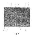
- the Fig. 3 shows a filled area 4 in an enlarged view.
- the particles 3 form second pores 5 in the filled regions 4, wherein the mean diameter of the particles 3 is greater than the average pore size of the plurality of second pores 5.
- the particles 3 are spherical and tend in some areas to form a densest spherical packing.
- Fig. 2 shows a coating of the particles 3, which is applied to the nonwoven fabric.
- the Fig. 1 to 3 show scanning electron micrographs of a layer with a nonwoven fabric whose fibers 1 are made of polyester.
- the particles 3 are spherical and form regions of agglomerates, which fill the first pores 2 of the nonwoven fabric.
- the fibers 1 show a mean diameter of less than 12 microns.
- the layer has a thickness of 25 microns. It shows a shrinkage in the transverse direction of less than 1% at a temperature of 170 ° C.
- the average diameter of the particles 3 is 200 nm.
- the particles 3 are made of polyvinylidene fluoride and were fixed to the fibers 1 by a binder of polyvinylpyrrolidone.
- the mean diameter of the particles 3 is determined from the number of particles 3 in the filled area 4.
- the particles 3 show a narrow distribution curve, that is to say an average diameter with a low standard deviation.
- the average pore sizes of most, namely the plurality, of the second pores 5 is less than 200 nm.
- the mean pore size of a second pore 5 is understood to be the diameter of a notional sphere 6 which has the same volume as the pore 5.
- the fictitious ball 6 lies between the particles 3 in such a way that it touches the surfaces of the adjacent particles 3.
- Fictitious balls 6, which characterize the dimension of the pores 5, are in FIG Fig. 3 shown as black-bordered hollow circles.
- a distribution curve whose x-axis shows the mean pore sizes of the second pores 5 and whose y-axis shows the number or frequency of the average pore sizes would prove that more than 50% of the second pores 5 show average pore sizes below 200 nm lie.
Landscapes
- Chemical Kinetics & Catalysis (AREA)
- Electrochemistry (AREA)
- General Chemical & Material Sciences (AREA)
- Chemical & Material Sciences (AREA)
- Engineering & Computer Science (AREA)
- Power Engineering (AREA)
- Microelectronics & Electronic Packaging (AREA)
- Cell Separators (AREA)
- Nonwoven Fabrics (AREA)
- Materials For Medical Uses (AREA)
- Separation Using Semi-Permeable Membranes (AREA)
- Laminated Bodies (AREA)
- Electric Double-Layer Capacitors Or The Like (AREA)
- Chemical Or Physical Treatment Of Fibers (AREA)
- Secondary Cells (AREA)
- Treatments For Attaching Organic Compounds To Fibrous Goods (AREA)
Description
- Die Erfindung betrifft eine Lage gemäß dem Oberbegriff des Patentanspruchs 1.
- Aus der
DE 102 38 944 A1 ist eine Lage aus einem Vlies aus Polymerfasern bekannt, welches eine keramische Beschichtung aufweist. Aus derUS 200510208383 A1 WO 2006/062153 A1 offenbart einen porösen Körper, in welchem Partikel und ein Harz aufgenommen sind. DieDE 31 25 751 A1 offenbart eine Lage, welche anorganische Partikel enthält Diese Partikel werden gemeinsam mit Polyolefinzellstofffasern in einen Brei eingearbeitet. Auf die Lage sind Prägenuten aufgebracht. Aus derDE 103 47 568 A1 ist ein poröser Körper bekannt, der mit einer keramischen Beschichtung versehen ist - Lagen der genannten Art sind aus dem Stand der Technik bereits bekannt. Solche Lagen werden als Separatoren in Batterien und Kondensatoren eingesetzt, die der Energiespeicherung dienen. Die Ladungsspeicherung in Batterien und Kondensatoren findet chemisch, physikalisch oder in einer Mischform, z. B. durch Chemisorption, statt.
- Um eine interne Entladung innerhalb der Batterie oder des Kondensators zu vermeiden, werden entgegengesetzt geladene Elektroden mechanisch durch nicht elektronenleitende Materialien, so genannte Separatoren oder Spacer, voneinander getrennt. Zugleich ermöglichen die Separatoren oder Spacer auf Grund ihrer dem Energiespeichersystem und dessen Anwendung angepassten Porosität den Transport ionischer Ladungsträger eines Elektrolyten zwischen den Elektroden.
- Die aus dem Stand der Technik bekannten Separatoren zeigen kleine, miteinander vernetzte Öffnungen im Mikrometerbereich. Diese Öffnungen sollen möglichst groß sein, damit die Elektrolytleitfähigkeit im getränkten Separator möglichst hoch ist und die Batterie somit eine hohe Leistungsdichte aufweist. Sind die Öffnungen jedoch zu groß, dann können Metalldendriten zu einem Kurzschluss zwischen den beiden eigentlich elektrisch voneinander zu trennenden Elektroden führen. Die Metalldendriten bestehen entweder aus Lithium oder aus anderen Metallen, die als Verunreinigungen in der Batterie vorliegen können.
- Des Weiteren können Partikel aus elektrisch leitfähigen Elektrodenmaterialien durch die Öffnungen wandern. Auf Grund dieser Vorgänge kann ein Kurzschluss zwischen den Elektroden entstehen und die Selbstentladung der Batterie oder des Kondensators stark beschleunigt werden.
- Bei einem Kurzschluss können lokal sehr hohe Ströme fließen, wodurch Wärme freigesetzt wird. Diese Wärme kann zum Schmelzen des Separators führen, wodurch wiederum die isolierende Wirkung des Separators deutlich nachlassen kann. Eine sich sehr schnell selbst entladende Batterie birgt dadurch auf Grund ihres hohen Energieinhaltes sowie der Brennbarkeit des Elektrolyten und anderer Bestandteile ein hohes Sicherheitsrisiko.
- Ein weiterer Nachteil der aus dem Stand der Technik bekannten Separatoren ist deren mangelnde Beständigkeit bei steigenden Temperaturen. Der Schmelzpunkt bei Verwendung von Polyethylen liegt bei rund 130°C bzw. rund 150°C bei Verwendung von Polypropylen.
- Als Ursachen für Kurzschlüsse können Schrumpf des Separators durch zu hohe Temperatur in der Batterie, Metalldendritenwachstum durch Reduktion von Metallionen (Lithium, Eisen, Mangan oder sonstige metallische Verunreinigungen), Abrieb von Elektrodenpartikeln, Schneidabrieb bzw. gebrochener Elektrodenbelag und unmittelbarer Kontakt der beiden flachen Elektroden unter Druck genannt werden.
- In der
EP 0 892 448 A2 ist der sogenannte "Shut down"-Mechanismus offenbart. Dieser wirkt bei lokaler Erwärmung durch beispielsweise einen Kurzschluss dessen flächiger Ausbreitung entgegen, indem die Ionenleitung in der Nähe des anfänglichen Kurzschlusses unterdrückt wird. Durch die Verlustwärme des Kurzschlusses wird Polyethylen so weit erhitzt, dass es schmilzt und die Poren des Separators verschließt. Höher schmelzendes Polypropylen bleibt mechanisch intakt. - Die
US 2002/0168569 A1 beschreibt den Aufbau eines Separators bestehend aus Polyvinyldifluorid, welches im Herstellungsprozess mit einem Lösemittel angelöst, mit Siliziumdioxid-Partikeln vermengt und als dünner Film ausgebracht wird. Beim Entfernen des Lösemittels bleibt eine poröse Membran zurück. - Die
WO 2006/068428 A1 beschreibt die Herstellung von Separatoren für Lithium-Ionen-Batterien unter Verwendung eines Polyolefin-Separators der zusätzlich mit gelartigen Polymeren und anorganischen Partikel gefüllt wird. - Die
WO 20041021475 A1 - Um eine ausreichende mechanische Flexibilität einzustellen, werden die Keramikpartikel in ein Stützmaterial, beispielsweise einen Vliesstoff eingebracht. Dies offenbart die
WO 2005/038959 A1 . - Um Kurzschlüsse im Anfangsstadium der Metalldendritenbildung zu unterbinden, wird in der
WO 2005/104269 A1 der Einsatz von niederschmelzenden Wachsen als Beimengung zu einer Keramikpaste beschrieben. - In der
WO 2007/028662 A1 wird der Zusatz von Polymerpertikeln mit einem Schmelzpunkt von über 100° C zu keramischen Füllstoffen beschrieben, um die mechanischen Eigenschaften des Separators zu verbessern. Die beschriebenen Materialien sollen als Separator für Lithium-Ionen Materialien dienen. Obwohl mit diesen Separatoren eine höhere Temperaturbeständigkeit im Vergleich zu Membranen erzielt werden kann, können sie sich noch nicht kommerziell durchsetzen. Dies kann einerseits an den relativ hohen Kosten und andererseits an der zu hohen Materialdicke liegen, welche über 25 µm liegt. - Die
WO 2000/024075 A1 beschreibt die Herstellung einer Membran, die in Brennstoffzellen eingesetzt werden kann. Diese besteht aus Glasfasermaterialien, in welchen mittels eines Silikatbinders Fluorkohlenwasserstoffpolymere fixiert werden. - Schließlich beschreibt die
JP 2005268096 A - Der Stand der Technik zeigt jedoch keinen kostengünstigen Separator, der bei geringer Dicke eine hohe Porosität und eine hohe Temperaturstabilität zeigt und in Batterien mit hoher Leistungs- und Energiedichte über einen weiten Temperaturbereich bei hohen Sicherheitsanforderungen einsetzbar ist.
- Der Erfindung liegt daher die Aufgabe zu Grunde, eine Lage der eingangs genannten Art derart auszugestalten und weiterzubilden, dass sie nach kostengünstiger Fertigung bei geringer Dicke eine hohe Porosität und hohe Temperaturstabilität aufweist.
- Die vorliegende Erfindung löst die zuvor genannte Aufgabe durch die Merkmale des Patentanspruchs 1.
- Die Häufigkeitsverteilung der mittleren Porengrößen wird erfindungsgemäß derart eingestellt, dass mehr als 50 % der zweiten Poren mittlere Porengrößen zeigen, die unterhalb des mittleren Durchmessers der Partikel liegen. Erfindungsgemäß ist erkannt worden, dass die Porenstruktur eines kostengünstigen Vliesstoffs durch geeignete Anordnung und Auswahl von Partikeln modifiziert werden kann. Ganz konkret ist erkannt worden, dass die Porosität der erfindungsgemäßen Lage im Vergleich zu Polyolefin-Membranen gesteigert werden kann, ohne deren Stabilität zu vermindern. Die Anordnung einer Vielzahl von Partikeln, deren mittlerer Durchmesser größer als die mittlere Porengröße der Mehrzahl der zweiten Poren im befüllten Bereich ist, erlaubt die Ausbildung einer hohen Porosität und damit eine begünstigte Elektrolyt-Aufnahme durch den Vliesstoff. Zugleich wird eine Porenstruktur geschaffen, in der sich nahezu keine schädlichen Metalldendriten ausbilden können. Durch die erfindungsgemäße Anordnung der Partikel kann eine Porenstruktur erzeugt werden, die nicht blasenartig, sondern labyrinthartig ist und gestreckte Poren aufweist. Bei einer solchen Porenstruktur können sich dendritartige Durchwachsungen nahezu nicht von einer Seite der Lage zur anderen Seite durchgängig ausbilden. Insoweit werden Kurzschlüsse in Batterien oder Kondensatoren wirksam verhindert. Die erfindungsgemäße Lage eignet sich daher besonders als Separator für Batterien und Kondensatoren mit hoher Leistungs- und Energiedichte. Die erfindungsgemäße Lage ist über einen weiten Temperaturbereich bei hohen Sicherheitsanforderungen einsetzbar.
- Die Partikel sind im Grundkörper flächig homogen verteilt. Durch diese konkrete Ausgestaltung können Kurzschlüsse besonders wirksam verhindert werden. Metalldendriten und Abrieb können durch eine homogen belegte Fläche nahezu nicht hindurchwandern. Des Weiteren wird der unmittelbare Kontakt von Elektroden bei Druckbeaufschlagung durch eine solche Fläche vermieden. Vor diesem Hintergrund ist konkret denkbar, dass sämtliche erste Poren des Vliesstoffes homogen derart mit den Partikeln ausgefüllt sind, dass die Lage vorliegend mittlere Porengrößen zeigt, die kleiner sind als die mittleren Durchmesser der Partikel.
- Der Grundkörper weist eine Beschichtung aus den Partikeln auf. Eine Beschichtung bewirkt ebenfalls vorteilhaft die zuvor genannte Unterdrückung von Kurzschlüssen. Wenn eine Lage mit einer Beschichtung versehen ist, tritt zwangsläufig ein Grenzbereich am Grundkörper auf, der zumindest teilweise mit Partikeln gefüllt ist.
- Vor diesem Hintergrund werden Mischungen aus Partikeln mit unterschiedlichen Schmelzpunkten verwendet. Hierdurch kann ein schrittweises oder stufenweises Verschließen der Poren mit zunehmender Temperatur bewirkt werden.
- Die Partikel sind aus organischen Polymeren, insbesondere aus Polypropylen, Polyvinylpyrrolidon, Polyvinylidenfluorid, Polyester, Polytetrafluorethylen, Perfluor-Ethylen-Propylen (FEP), Polystyrol, Styrolbutadiencopolymeren, Polyacrylaten oder Nitrilbutadienpolymeren sowie Copolymeren der zuvor genannten Polymere gefertigt. Die Verwendung organischer Polymere für die Partikel erlaubt ein problemloses Aufschmelzen der Partikel zur Erzielung eines "Shut-Down-Effektes". Des Weiteren kann eine Lage gefertigt werden, die sich problemlos zuschneiden lässt, ohne zu zerbröseln. Ein Zerbröseln der Lage tritt meist dann auf, wenn ein relativ hoher Anteil an anorganischen Partikeln in der Lage vorliegt. Vor diesem Hintergrund ist denkbar, Mischungen unterschiedlicher Partikel oder Core-Shell-Partikel zu verwenden. Hierdurch kann ein schrittweises oder stufenweises Verschließen der Poren mit zunehmender Temperatur bewirkt werden.
- Die Lage zeigt eine Höchstzugkraft in Längsrichtung von mindestens 15 Newton/5cm. Eine Lage dieser Festigkeit lässt sich besonders problemlos auf die Elektroden einer Batterie aufwickeln, ohne zu zerreißen.
- Durch eine Kalandrierung ist die Lage mechanisch verfestigt. Die Kalandrierung bewirkt eine Reduzierung der Oberflächenrauhigkeit. Die an der Oberfläche des Vliesstoffs eingesetzten Partikel zeigen nach der Kalandrierung Abplattungen.
- Der Schmelzpunkt der Partikel liegt unter den Schmelzpunkten der Fasern des Vliesstoffs. Durch die Auswahl solcher Partikel kann die Lage einen so genannten "Shut-Down-Mechanismus" realisieren. Bei einem "Shut-Down-Mechanismus" verschließen die aufschmelzenden Partikel die Poren des Vliesstoffs, so dass keine dendritartigen Durchwachsungen durch die Poren und somit Kurzschlüsse auftreten können.
- Folglich ist die eingangs genannte Aufgabe gelöst.
- Die Partikel könnten kugelförmig sein. Hierdurch kann vorteilhaft eine überwiegend dichteste Kugelpackung in den ersten Poren des Vliesstoffs erzeugt werden. Die mittlere Porengröße der Mehrzahl der zweiten Poren wird im wesentlichen durch geometrischen Verhältnisse in Kugelpackungen bestimmt. Es gibt unendlich viele Möglichkeiten, eine dichteste Kugelpackung herzustellen. Gemein ist ihnen, dass sie aus hexagonalen Kugel-Schichten bestehen. Die zwei wichtigsten Vertreter sind die hexagonal dichteste Kugelpackung (Schichtfolge A, B, A, B, A, B) und die kubisch dichteste Kugelpackung (Schichitfolge A, B, C, A, B, C, A). Die kubisch dichteste Kugelpackung wird auch kubisch flächenzentrierte Kugelpackung genannt. In einer dichtesten Kugelpackung hat jede Kugel 12 nächste Nachbarn, sechs in der eigenen Schicht, sowie drei je darüber und darunter. Sie bilden bei der kubischen Packung einen Kuboktaeder, bei der hexagonalen einen Antikuboktaeder. Der Raumfüllungsgrad einer dichtesten Kugelpackung beträgt 74%. Es wird jedoch angestrebt, eine möglichst hohe Porosität zu erzeugen. Daher werden nicht alle Partikel in den ersten Poren des Vliesstoffs eine dichteste Kugelpackung ausbilden. Vielmehr werden auch Zonen loser Schüttung der Partikel auftreten, wodurch eine hohe Porosität begünstigt wird.
- Die Partikel könnten durch einen Binder mit dem Vliesstoff bzw. untereinander verbunden sein. Dabei könnte der Binder aus organischen Polymeren bestehen. Die Verwendung eines Binders aus organischen Polymeren erlaubt es, eine Lage mit ausreichender mechanischer Flexibilität herzustellen. Ausgezeichnete Bindereigenschaften zeigt überraschenderweise Polyvinylpyrrolidon.
- Bevorzugt könnten thermoplastische und/oder duroplastische Binder verwendet werden. Beispielhaft seien vor diesem Hintergrund Polyvinylpyrrolidon, Polyacrylsäure, Polyacrylate, Polymethacrylsäure, Polymethacrylate, Polystyrol, Polyvinylalkohol, Polyvinylacetat, Polyacrylamid und Copolymere aus den vorgenannten, Cellulose und deren Derivate, Polyether, Phenolharze, Melaminharze, Polyurethane, Nitrilkautschuk (NBR), Styrolbutadienkautschuk (SBR) sowie Latex genannt.
- Der Schmelzpunkt des Binders könnte unter den Schmelzpunkten der Fasern des Vliesstoffs liegen. Durch die Auswahl eines solchen Binders kann die Lage einen so genannten "Shut-Down-Mechanismus" realisieren. Bei einem "Shut-Down-Mechanismus" verschließt der Binder die Poren des Vliesstoffs, so dass keine dendritartigen Durchwachsungen durch die Poren und somit Kurzschlüsse auftreten können.
- Die Partikel könnten einen mittleren Durchmesser im Bereich von 0,01 bis 10 µm aufweisen. Die Auswahl des mittleren Durchmessers aus diesem Bereich hat sich als besonders vorteilhaft erwiesen, um Kurzschlüsse durch Ausbildung von dendritartigen Durchwachsungen oder Abrieb zu vermeiden.
- Denkbar ist auch, anorganische Partikel oder anorganisch-organische Hybridpartikel einzusetzen. Diese Partikel schmelzen nicht unterhalb einer Temperatur von 400° C. Des Weiteren können diese Partikel mit basischen Eigenschaften gewählt werden, um die in Batterien vorliegende Protonenaktivität zumindest teilweise zu vermindern.
- Die Fasern des Vliesstoffs könnten aus organischen Polymeren, insbesondere aus Polybutylterephtalat, Polyethylenterephtalat, Polyacrylnitril, Polyvinylidenfluorid, Polyetheretherketonen, Polyethylennaphtalat, Polysulfonen, Polyimid, Polyester, Polypropylen, Polyoxymethylen, Polyamid oder Polyvinylpyrrolidon gefertigt sein. Denkbar ist auch, Bikomponentenfasern einzusetzen, welche die zuvor genannten Polymere aufweisen. Die Verwendung dieser organischen Polymere erlaubt es, eine Lage herzustellen, die nur einen geringen thermischen Schrumpf zeigt. Des Weiteren sind diese Materialien weitgehend elektrochemisch stabil gegenüber den in Batterien und Kondensatoren eingesetzten Elektrolyten und Gasen.
- Die mittlere Länge der Fasern des Vliesstoffs könnte deren mittleren Durchmesser um mindestens das zweifache, vorzugsweise ein Vielfaches übersteigen. Durch diese konkrete Ausgestaltung kann ein besonders reißfester Vliesstoff gefertigt werden, da die Fasern miteinander verschlungen werden können.
- Mindestens 90% der Fasern des Vliesstoffs könnten einen mittleren Durchmesser von höchstens 12 µm aufweisen. Diese konkrete Ausgestaltung erlaubt den Aufbau einer Lage mit relativ geringen Porengrößen der ersten Poren. Eine noch feinere Porosität kann dadurch erzielt werden, dass mindestens 40% der Fasern des Vliesstoffs einen mittleren Durchmesser von höchstens 8 µm aufweisen.
- Die Lage könnte durch eine Dicke von höchstens 100 µm gekennzeichnet sein. Eine Lage dieser Dicke lässt sich noch problemlos aufwickeln und erlaubt einen sehr sicheren Batteriebetrieb. Bevorzugt könnte die Dicke höchstens 60 µm betragen. Diese Dicke erlaubt eine verbesserte Aufwickelbarkeit und dennoch einen sicheren Batteriebetrieb. Besonders bevorzugt könnte die Dicke höchstens 25 µm betragen. Mit Lagen einer solchen Dicke können sehr kompakt bauende Batterien und Kondensatoren gebaut werden.
- Die Lage könnte eine Porosität von mindestens 25 % aufweisen. Eine Lage dieser Porosität unterdrückt aufgrund ihrer Materialdichte besonders effektiv die Ausbildung von Kurzschlüssen. Bevorzugt könnte die Lage eine Porosität von mindestens 35 % aufweisen. Durch eine Lage dieser Porosität kann eine Batterie mit hoher Leistungsdichte erzeugt werden. Die hier beschriebene Lage zeigt bei hoher Porosität dennoch sehr kleine zweite Poren, so dass sich keine dendritartigen Durchwachsungen von einer Seite zur anderen Seite der Lage ausbilden können. Vor diesem Hintergrund ist denkbar, dass die zweiten Poren ein labyrinthartiges Gefüge ausbilden, in dem sich keine dendritartigen Durchwachsungen von einer Seite zur anderen Seite der Lage ausbilden können.
- Die Lage könnte Porengrößen von höchstens 3 µm aufweisen. Die Auswahl dieser Porengröße hat sich als besonders vorteilhaft erwiesen, um Kurzschlüsse zu vermeiden. Besonders bevorzugt könnten die Porengrößen höchstens 1 µm betragen. Eine solche Lage vermeidet besonders vorteilhaft Kurzschlüsse durch Metalldendritenwachstum, durch Abrieb aus Elektrodenpartikeln und durch unmittelbaren Kontakt der Elektroden bei Druckbeaufschlagung.
- Die hier beschriebene Lage kann insbesondere in Batterien und Kondensatoren als Separator eingesetzt werden, da sie Kurzschlüsse besonders wirksam verhindert.
- Sie kann auch in Brennstoffzellen als Gasdiffusionsschicht oder Membran Verwendung finden, da sie gute Benetzungseigenschaften zeigt und Flüssigkeiten transportieren kann.
- Es gibt nun verschiedene Möglichkeiten, die Lehre der vorliegenden Erfindung in vorteilhafter Weise auszugestalten und weiterzubilden. Dazu ist einerseits auf die nachgeordneten Patentansprüche, andererseits auf die nachfolgende Erläuterung eines bevorzugten Ausführungsbeispiels der Erfindung anhand der Zeichnung zu verweisen.
- In Verbindung mit der Erläuterung des bevorzugten Ausführungsbeispiels der Erfindung anhand der Zeichnung werden auch im Allgemeinen bevorzugte Ausgestaltungen und Weiterbildungen der Lehre erläutert.
- In der Zeichnung zeigen
- Fig. 1
- eine Rasterelektronenmikroskop-Aufnahme einer Lage, in welcher die Partikel in ersten Poren eines Vliesstoffs vorliegen und einen porösen mit Partikeln befüllten Bereich ausbilden,
- Fig. 2
- eine Rasterelektronenmikroskop-Aufnahme der Partikel eines befüllten Bereichs, der als Beschichtung ausgebildet ist, und
- Fig. 3
- eine stark vergrößerte Rasterelektronenmikroskop-Aufnahme der Partikel eines befüllten Bereichs.
-
Fig. 1 zeigt eine Lage mit einem Grundkörper aus Vliesstoff, wobei der Grundkörper aus Fasern 1 besteht und erste durch die Fasern 1 gebildete Poren 2 aufweist, wobei der Grundkörper zumindest teilweise mit Partikeln 3 befüllt ist und wobei die Partikel 3 die ersten Poren 2 zumindest teilweise ausfüllen und mit Partikeln 3 befüllte Bereiche 4 ausbilden. - Die
Fig. 3 zeigt einen befüllten Bereich 4 in einer vergrößerten Ansicht, Mit Bezug aufFig. 3 bilden die Partikel 3 in den befüllten Bereichen 4 zweite Poren 5 aus, wobei der mittlere Durchmesser der Partikel 3 größter als die mittlere Porengröße der Mehrzahl der zweiten Poren 5 ist. Die Partikel 3 sind kugelförmig und neigen bereichsweise zur Ausbildung einer dichtesten Kugelpackung. -
Fig. 2 zeigt eine Beschichtung aus den Partikeln 3, die auf dem Vliesstoff aufgebracht ist. - Die
Fig. 1 bis 3 zeigen Rasterelektronenmikroskop-Aufnahmen einer Lage mit einem Vliesstoff, dessen Fasern 1 aus Polyester gefertigt sind. Die Partikel 3 sind kugelförmig ausgebildet und bilden bereichsweise Agglomerate, welche die ersten Poren 2 des Vliesstoffs ausfüllen. Die Fasern 1 zeigen einen mittleren Durchmesser von weniger als 12 µm. Die Lage weist eine Dicke von 25 µm auf. Sie zeigt einen Schrumpf in Querrichtung von weniger als 1 % bei einer Temperatur von 170° C. - Der mittlere Durchmesser der Partikel 3 beträgt 200 nm. Die Partikel 3 bestehen aus Polyvinylidenfluorid und wurden durch einen Binder aus Polyvinylpyrrolidon an den Fasern 1 befestigt.
- Der mittlere Durchmesser der Partikel 3 wird aus der Anzahl der Partikel 3 in dem befüllten Bereich 4 ermittelt. Bevorzugt zeigen die Partikel 3 eine enge Verteilungskurve, das heisst einen mittleren Durchmesser mit geringer Standardabweichung. Die mittleren Porengrößen der meisten, nämlich der Mehrzahl, der zweiten Poren 5 ist geringer als 200 nm. Unter mittlerer Porengröße einer zweiten Pore 5 wird der Durchmesser einer fiktiven Kugel 6 verstanden, welche das gleiche Volumen wie die Pore 5 aufweist. Die fiktive Kugel 6 liegt derart zwischen den Partikeln 3, dass sie die Oberflächen der benachbarten Partikel 3 berührt. Fiktive Kugeln 6, welche die Dimension der Poren 5 kennzeichnen, sind in
Fig. 3 als schwarz-umrandete Hohlkreise dargestellt. - Eine Verteilungskurve, deren x-Achse die mittleren Porengrößen der zweiten Poren 5 und deren y-Achse die Anzahl bzw. Häufigkeit der mittleren Porengrößen zeigt, würde belegen, dass mehr als 50% der zweiten Poren 5 mittlere Porengrößen zeigen, die unterhalb von 200 nm liegen.
- Hinsichtlich weiterer vorteilhafter Ausgestaltungen und Weiterbildungen der erfindungsgemäßen Lehre wird einerseits auf den allgemeinen Teil der Beschreibung und andererseits auf die beigefügten Patentansprüche verwiesen.
- Abschließend sei ganz besonders hervorgehoben, dass das zuvor rein willkürlich gewählte Ausführungsbeispiel lediglich zur Erörterung der erfindungsgemäßen Lehre dient, diese jedoch nicht auf dieses Ausführungsbeispiel einschränkt.
Claims (13)
- Lage mit einem Grundkörper aus Vliesstoff, wobei der Grundkörper aus Fasern (1) besteht und erste durch die Fasern (1) gebildete Poren (2) aufweist, wobei der Grundkörper zumindest teilweise mit Partikeln (3) befüllt ist, wobei die Partikel (3) die ersten Poren (2) zumindest teilweise ausfüllen und mit Partikeln (3) befüllte Bereiche (4) ausbilden, wobei die Partikel (3) in den befüllten Bereichen (4) zweite Poren (5) ausbilden, wobei der mittlere Durchmesser der Partikel (3) größer als die mittlere Porengröße der Mehrzahl der zweiten Poren (5) ist, wobei zumindest ein Teil der befüllten Bereiche (4) als Beschichtung des Grundkörpers mit den Partikeln (3) ausgebildet ist und wobei die Lage eine Höchstzugkraft von mindestens 15 N/5cm in Längsrichtung zeigt, wobei
der Grundkörper kalandriert ist, wobei die Partikel (3) im Grundkörper flächig homogen verteilt sind, und wobei die Partikel (3) aus organischen Polymeren gefertigt sind, die aus der Gruppe Polypropylen, Polyvinylpyrroildon, Polyvinylidenfluorid, Polyester, Polytetrafluorethylen, Perfluor-Ethylen-Propylen (FEP), Polystyrol, Styrolbutadiencopolymere, Polyacrylat oder Nitrilbutadienpolymere sowie Copolymere der zuvor genannten Polymere ausgewählt sind, dadurch gekennzeichnet, dass Mischungen aus Partikeln mit unterschiedlichen Schmelzpunkten derart verwendet sind, dass ein schrittweises oder stufenweises Verschließen der Poren mit zunehmender Temperatur bewirkt wird und wobei der Schmelzpunkt der Partikel unter den Schmelzpunkten der Fasern des Vliesstoffs liegt. - Lage nach Anspruch 1, dadurch gekennzeichnet, dass die Partikel (3) kugelförmig ausgebildet sind.
- Lage nach Anspruch 1 oder 2, dadurch gekennzeichnet, dass die Partikel (3) durch einen Binder aus organischen Polymeren mit dem Vliesstoff verbunden sind, die aus der Gruppe Polyvinylpyrrolidon, Polyacrylsäure, Polyacrylat, Polymethacrylsäure, Polymethacrylat, Polystyrol, Polyvinylalkohol, Polyvinylacetat, Polyacrylamid und Copolymere aus den vorgenannten, Cellulose und deren Derivate, Polyether, Phenolharz, Melaminharz, Polyurethan, Nitrilkautschuk (NBR), Styrolbutadienkautschuk (SBR) sowie Latex ausgewählt sind.
- Lage nach einem der Ansprüche 1 bis 3, dadurch gekennzeichnet, dass der Schmelzpunkt des Binders unter den Schmelzpunkten der Partikel (3) und/ oder der Fasern (1) liegt.
- Lage nach einem der Ansprüche 1 bis 4, dadurch gekennzeichnet, dass die Partikel (3) einen mittleren Durchmesser im Bereich von 0,01 und 10 µm aufweisen.
- Lage nach einem der Ansprüche 1 bis 5, dadurch gekennzeichnet, dass die Fasern (1) des Vliesstoffs aus organischen Polymeren gefertigt sind, die aus der Gruppe Polybutylterephtalat, Polyethylenterephtalat, Polyacrylnitril, Polyvinylidenfluorid, Polyetheretherketon, Polyethylennaphtalat, Polysulfon, Polyimid, Polyester, Polypropylen, Polyoxymethylen, Polyamid oder Polyvinylpyrrolidon ausgewählt sind.
- Lage nach einem der Ansprüche 1 bis 6, dadurch gekennzeichnet, dass die mittlere Länge der Fasern (1) des Vliesstoffs deren mittleren Durchmesser um mindestens das zweifache, vorzugsweise ein vielfaches, übersteigt.
- Lage nach einem der Ansprüche 1 bis 7, dadurch gekennzeichnet, dass mindestens 90% der Fasern (1) des Vliesstoffs einen mittleren Durchmesser von höchstens 12 µm aufweisen.
- Lage nach einem der Ansprüche 1 bis 8, dadurch gekennzeichnet, dass mindestens 40% der Fasern (1) des Vliesstoffs einen mittleren Durchmesser von höchstens 8 µm aufweisen.
- Lage nach einem der Ansprüche 1 bis 9, gekennzeichnet durch eine Dicke von höchstens 100 µm, bevorzugt von höchstens 60 µm und besonders bevorzugt von 25 µm.
- Lage nach einem der Ansprüche 1 bis 10, gekennzeichnet durch eine Porosität von mindestens 25 %, bevorzugt von mindestens 35 %.
- Lage nach einem der Ansprüche 1 bis 11, dadurch gekennzeichnet, dass die ersten und die zweiten Poren (2, 5) ein labyrinthartiges Gefüge ausbilden.
- Lage nach einem der Ansprüche 1 bis 12, gekennzeichnet durch eine Porengröße der zweiten Poren (5) von höchstens 3 µm, bevorzugt von höchstens 1 µm.
Applications Claiming Priority (2)
| Application Number | Priority Date | Filing Date | Title |
|---|---|---|---|
| DE102007042554.8A DE102007042554B4 (de) | 2007-09-07 | 2007-09-07 | Vliesstoff mit Partikelfüllung |
| PCT/EP2008/004824 WO2009033514A1 (de) | 2007-09-07 | 2008-06-16 | Vliesstoff mit partikelfüllung |
Publications (2)
| Publication Number | Publication Date |
|---|---|
| EP2186149A1 EP2186149A1 (de) | 2010-05-19 |
| EP2186149B1 true EP2186149B1 (de) | 2011-08-17 |
Family
ID=39846619
Family Applications (3)
| Application Number | Title | Priority Date | Filing Date |
|---|---|---|---|
| EP20080001406 Active EP2034540B1 (de) | 2007-09-07 | 2008-01-25 | Vliesstoff mit Partikelfüllung |
| EP08784516A Not-in-force EP2186149B1 (de) | 2007-09-07 | 2008-06-16 | Vliesstoff mit partikelfüllung |
| EP08830103A Not-in-force EP2235766B1 (de) | 2007-09-07 | 2008-09-08 | Vliesstoff mit partikelfüllung |
Family Applications Before (1)
| Application Number | Title | Priority Date | Filing Date |
|---|---|---|---|
| EP20080001406 Active EP2034540B1 (de) | 2007-09-07 | 2008-01-25 | Vliesstoff mit Partikelfüllung |
Family Applications After (1)
| Application Number | Title | Priority Date | Filing Date |
|---|---|---|---|
| EP08830103A Not-in-force EP2235766B1 (de) | 2007-09-07 | 2008-09-08 | Vliesstoff mit partikelfüllung |
Country Status (12)
| Country | Link |
|---|---|
| US (2) | US20100196688A1 (de) |
| EP (3) | EP2034540B1 (de) |
| JP (2) | JP5470643B2 (de) |
| KR (2) | KR101123984B1 (de) |
| CN (3) | CN108023049B (de) |
| AT (3) | ATE518265T1 (de) |
| BR (2) | BRPI0816369B1 (de) |
| DE (1) | DE102007042554B4 (de) |
| ES (3) | ES2368014T3 (de) |
| HK (1) | HK1254291A1 (de) |
| RU (2) | RU2427944C1 (de) |
| WO (2) | WO2009033514A1 (de) |
Cited By (1)
| Publication number | Priority date | Publication date | Assignee | Title |
|---|---|---|---|---|
| US8999602B2 (en) | 2012-02-27 | 2015-04-07 | Basf Se | Separators for electrochemical cells comprising polymer particles |
Families Citing this family (69)
| Publication number | Priority date | Publication date | Assignee | Title |
|---|---|---|---|---|
| DE102007042554B4 (de) * | 2007-09-07 | 2017-05-11 | Carl Freudenberg Kg | Vliesstoff mit Partikelfüllung |
| RU2485634C2 (ru) * | 2008-02-20 | 2013-06-20 | Карл Фройденберг Кг | Нетканый материал, содержащий сшивающий материал |
| DE102009017542A1 (de) | 2009-04-17 | 2010-10-28 | Carl Freudenberg Kg | Unsymmetrischer Separator |
| FR2957610B1 (fr) | 2010-03-17 | 2012-03-23 | Freudenberg Politex Sa | Produit non-tisse contenant des particules organiques et/ou minerales et son procede de fabrication |
| BR112012033046B1 (pt) * | 2010-08-11 | 2020-09-24 | Carl Freudenberg Kg | Separador com um corpo básico de não tecido |
| JP5699576B2 (ja) * | 2010-12-08 | 2015-04-15 | ソニー株式会社 | 積層型微多孔膜、電池用セパレータおよび非水電解質電池 |
| CN102587038B (zh) * | 2011-01-04 | 2014-10-08 | 扬光绿能股份有限公司 | 无纺布、无纺布的制造方法及气体产生装置 |
| EP2666199B1 (de) * | 2011-01-19 | 2017-06-21 | E. I. du Pont de Nemours and Company | Lithiumbatterieseparator mit abschaltfunktion |
| JP2014513395A (ja) | 2011-04-04 | 2014-05-29 | ビーエーエスエフ ソシエタス・ヨーロピア | イオン交換体を有する電気化学セル |
| US20120251884A1 (en) * | 2011-04-04 | 2012-10-04 | Basf Se | Electrochemical cells comprising ion exchangers |
| US8828489B2 (en) * | 2011-08-19 | 2014-09-09 | International Business Machines Corporation | Homogeneous modification of porous films |
| US20130149589A1 (en) * | 2011-12-07 | 2013-06-13 | Oliver Gronwald | Electrochemical cells comprising a nitrogen-containing polymer |
| JP5951982B2 (ja) * | 2011-12-26 | 2016-07-13 | 帝人株式会社 | 非水系二次電池用セパレータおよび非水系二次電池 |
| US20130189550A1 (en) * | 2012-01-23 | 2013-07-25 | Nicole JANSSEN | Composite, its production and its use in separators for electrochemical cells |
| DE102013200722A1 (de) | 2012-01-30 | 2013-08-01 | Evonik Litarion Gmbh | Separator enthaltend eine organisch-anorganische Haftvermittlerkomponente |
| CN109119575A (zh) * | 2012-02-21 | 2019-01-01 | 阿科玛股份有限公司 | 水性聚偏二氟乙烯组合物 |
| JP2015517174A (ja) | 2012-02-27 | 2015-06-18 | ビーエーエスエフ ソシエタス・ヨーロピアBasf Se | ポリマー粒子を含む電気化学セル用のセパレータ |
| US9887406B2 (en) | 2012-03-09 | 2018-02-06 | Teijin Limited | Separator for non-aqueous secondary battery, method for manufacturing the same, and non-aqueous secondary battery |
| JP5829570B2 (ja) * | 2012-04-24 | 2015-12-09 | 三菱製紙株式会社 | 金属イオン二次電池用セパレータの製造方法 |
| WO2014016347A1 (de) | 2012-07-25 | 2014-01-30 | Lanxess Deutschland Gmbh | Nanofiltrationsmembran mit einer schicht aus polymer- und oxidpartikeln |
| JP5941371B2 (ja) * | 2012-08-20 | 2016-06-29 | Jmエナジー株式会社 | リチウムイオンキャパシタ |
| KR101699037B1 (ko) * | 2012-11-12 | 2017-01-23 | 주식회사 엘지화학 | 세퍼레이터의 제조방법, 그에 의해 제조된 세퍼레이터 및 그를 포함하는 전기화학소자 |
| DE102013200707A1 (de) * | 2013-01-18 | 2014-07-24 | Robert Bosch Gmbh | Galvanisches Element mit verbessertem Sicherheitseigenschaften |
| KR101455852B1 (ko) * | 2013-01-28 | 2014-10-27 | 뉴로엘리싯 주식회사 | 이차전지용 유무기 다공성분리막의 제조방법 및 이로부터 제조된 유무기 다공성분리막 |
| KR101703957B1 (ko) * | 2013-10-31 | 2017-02-08 | 주식회사 엘지화학 | 유기-무기 복합 다공성 막, 이를 포함하는 세퍼레이터 및 전극 구조체 |
| KR101796283B1 (ko) | 2013-11-05 | 2017-11-10 | 주식회사 엘지화학 | 부직포 기재를 포함하는 복합 세퍼레이터 및 그의 제조방법 |
| US9761854B2 (en) * | 2013-12-13 | 2017-09-12 | Samsug SDI Co., Ltd. | Spirally-wound electrode assembly for rechargeable lithium battery and rechargeable lithium battery including same |
| US9887407B2 (en) * | 2014-04-04 | 2018-02-06 | Lg Chem, Ltd. | Secondary battery with improved life characteristics |
| JP6399921B2 (ja) | 2014-12-22 | 2018-10-03 | 三星エスディアイ株式会社Samsung SDI Co., Ltd. | 非水電解質二次電池用電極巻回素子、それを用いた非水電解質二次電池、及び非水電解質二次電池用電極巻回素子の製造方法 |
| US10014557B2 (en) | 2014-12-22 | 2018-07-03 | Samsung Sdi Co., Ltd. | Electrode winding element for non-aqueous electrolyte rechareable battery, non-aqueous electrolyte rechargeable lithium battery including same, method of preparing same |
| US10256471B2 (en) | 2014-12-22 | 2019-04-09 | Samsung Sdi Co., Ltd. | Electrode winding element for non-aqueous electrolyte rechareable battery, non-aqueous electrolyte rechargeable lithium battery including same, method of preparing same |
| WO2016123404A1 (en) * | 2015-01-28 | 2016-08-04 | Hercules Incorporated | Ceramic binder composition for ceramic coated separator for lithium ion batteries, methods of producing same, and uses thereof |
| CN107431234A (zh) * | 2015-03-24 | 2017-12-01 | 日本电气株式会社 | 高安全性且高能量密度的电池 |
| CN105226219B (zh) * | 2015-09-11 | 2017-07-11 | 江西先材纳米纤维科技有限公司 | 氧化锆颗粒填充的复合多曲孔膜材料及其制备方法和应用 |
| CN105098125B (zh) * | 2015-09-11 | 2017-07-11 | 江西先材纳米纤维科技有限公司 | 氧化铝颗粒填充的复合多曲孔膜材料及其制备方法和应用 |
| CN105206782B (zh) * | 2015-09-11 | 2017-04-05 | 江西师范大学 | PI‑Si3N4‑PTFE三元纳米复合多曲孔膜材料及其制备方法和应用 |
| CN105244466B (zh) * | 2015-09-11 | 2017-07-11 | 江西先材纳米纤维科技有限公司 | 二氧化硅颗粒填充的复合多曲孔膜材料及其制备方法和应用 |
| CN105070869B (zh) * | 2015-09-11 | 2016-08-31 | 江西师范大学 | Pi-bn-ptfe三元纳米复合多曲孔膜材料及其制备方法和应用 |
| CN105047847B (zh) * | 2015-09-11 | 2017-04-05 | 江西师范大学 | PI‑AlN‑PTFE三元纳米复合多曲孔膜材料及其制备方法和应用 |
| KR102546315B1 (ko) * | 2015-09-25 | 2023-06-21 | 삼성전자주식회사 | 리튬전지용 전극 복합분리막 어셈블리 및 이를 포함한 리튬전지 |
| KR102496375B1 (ko) * | 2015-11-20 | 2023-02-06 | 삼성전자주식회사 | 리튬전지용 전극 복합분리막 어셈블리 및 이를 포함한 리튬전지 |
| JP7115463B2 (ja) * | 2017-02-24 | 2022-08-09 | 日本ゼオン株式会社 | 非水系二次電池用バインダー組成物、非水系二次電池機能層用スラリー組成物、非水系二次電池用機能層、および非水系二次電池 |
| WO2018175134A1 (en) * | 2017-03-23 | 2018-09-27 | Boston Materials Llc | Fiber-reinforced composites, methods therefor, and articles comprising the same |
| EP3385435A1 (de) * | 2017-04-03 | 2018-10-10 | Lenzing Aktiengesellschaft | Cellulosefaservliesstoff mit verschiedenen porensätzen |
| CA3075644A1 (en) | 2017-10-09 | 2019-04-18 | Owens Corning Intellectual Capital, Llc | Aqueous binder compositions |
| US11111372B2 (en) | 2017-10-09 | 2021-09-07 | Owens Corning Intellectual Capital, Llc | Aqueous binder compositions |
| JP6411689B1 (ja) * | 2018-03-29 | 2018-10-24 | ニッポン高度紙工業株式会社 | 固体電解コンデンサ又はハイブリッド電解コンデンサ用セパレータ及び固体電解コンデンサ又はハイブリッド電解コンデンサ。 |
| CN115528379A (zh) | 2018-04-11 | 2022-12-27 | 宁德新能源科技有限公司 | 隔离膜及储能装置 |
| US11367927B2 (en) * | 2018-05-14 | 2022-06-21 | International Business Machines Corporation | Separator for energy storage device |
| US11840028B2 (en) | 2018-12-10 | 2023-12-12 | Boston Materials, Inc. | Systems and methods for carbon fiber alignment and fiber-reinforced composites |
| EP3669973A1 (de) * | 2018-12-20 | 2020-06-24 | Evonik Operations GmbH | Verbundkörper |
| WO2020210191A1 (en) | 2019-04-09 | 2020-10-15 | Owens Corning Intellectual Capital, Llc | Insulation products formed with aqueous binder compositions |
| AU2020270841A1 (en) | 2019-04-09 | 2021-12-02 | Owens Corning Intellectual Capital, Llc | Aqueous binder compositions |
| WO2020223411A1 (en) * | 2019-04-29 | 2020-11-05 | Cocona, Inc. | Method to incorporate particles in natural fibers and materials |
| CN112018305A (zh) * | 2019-05-30 | 2020-12-01 | 财团法人工业技术研究院 | 复合膜及其制作方法与应用 |
| WO2021007381A1 (en) | 2019-07-10 | 2021-01-14 | Boston Materials, Inc. | Systems and methods for forming short-fiber films, composites comprising thermosets, and other composites |
| JP7444561B2 (ja) * | 2019-08-08 | 2024-03-06 | 株式会社東芝 | アルミニウム電解コンデンサ、電気機器、及びアルミニウム電解コンデンサの製造方法 |
| US11813833B2 (en) | 2019-12-09 | 2023-11-14 | Owens Corning Intellectual Capital, Llc | Fiberglass insulation product |
| CN114787261B (zh) | 2019-12-09 | 2024-06-14 | 欧文斯科宁知识产权资产有限公司 | 玻璃纤维绝缘产品 |
| CN111211272B (zh) * | 2020-01-10 | 2022-05-10 | 武汉中兴创新材料技术有限公司 | 一种涂层隔膜、涂覆浆料和制备方法 |
| JP7447550B2 (ja) * | 2020-03-02 | 2024-03-12 | トヨタ紡織株式会社 | セパレータおよびセパレータの製造方法 |
| CN111509252A (zh) * | 2020-05-06 | 2020-08-07 | 一汽解放汽车有限公司 | 一种气体扩散层及其制备方法和应用 |
| KR102490379B1 (ko) * | 2020-06-25 | 2023-01-20 | 제주대학교 산학협력단 | 압전 섬유를 포함하는 자가 충전 슈퍼 커패시터에서의 충전-저장을 모니터링 하기 위한 검증 방법 및 슈퍼 커패시터의 제조방법 |
| EP4386122B1 (de) * | 2020-07-30 | 2025-11-05 | 3M Innovative Properties Co. | Barriere gegen thermisches durchgehen für eine batterie |
| KR20230082034A (ko) | 2020-10-01 | 2023-06-08 | 오웬스 코닝 인텔렉츄얼 캐피탈 엘엘씨 | B-스테이지 가능한 수성 결합제 조성물 |
| AU2022284877A1 (en) | 2021-06-04 | 2023-11-02 | Owens Corning Intellectual Capital, Llc | Fine fiber insulation products with improved thermal properties |
| DE102021121361A1 (de) | 2021-08-17 | 2023-02-23 | Fraunhofer-Gesellschaft zur Förderung der angewandten Forschung eingetragener Verein | Verfahren zur Herstellung einer Feststoff-Batterie mit porösem Stützkörper, und Feststoff-Batterie mit porösem Stützkörper |
| CN116613470B (zh) * | 2023-05-04 | 2025-05-30 | 浙江锂威能源科技有限公司 | 隔膜及含该隔膜的二次电池、用电装置 |
| US20260062598A1 (en) | 2024-09-03 | 2026-03-05 | Boston Materials, Inc. | Liquid metal compositions and methods |
Family Cites Families (57)
| Publication number | Priority date | Publication date | Assignee | Title |
|---|---|---|---|---|
| US1983450A (en) * | 1932-09-20 | 1934-12-04 | Viscose Co | Delustered rayon and spinning solution therefor |
| US3022366A (en) * | 1955-03-30 | 1962-02-20 | Pittsburgh Plate Glass Co | Battery separator and manufacture thereof |
| NL6706132A (de) * | 1966-05-03 | 1967-11-06 | ||
| DE2655024C3 (de) * | 1976-12-04 | 1982-04-22 | Fa. Carl Freudenberg, 6940 Weinheim | Trägerschicht für eine semipermeable Membran |
| CA1172310A (en) * | 1980-06-30 | 1984-08-07 | Stanley J. Strzempko | Battery separator material |
| DE3605981A1 (de) * | 1986-02-25 | 1987-08-27 | Goetze Ag | Weichstoffflachdichtungsmaterial |
| GB8608430D0 (en) | 1986-04-07 | 1986-05-14 | Raychem Ltd | Porous polymer article |
| JPS63135569A (ja) * | 1986-11-18 | 1988-06-07 | 三井東圧化学株式会社 | 通気性防水不織布 |
| SU1757408A1 (ru) * | 1990-08-22 | 1994-08-30 | Научно-исследовательский проектно-конструкторский и технологический институт стартерных аккумуляторов | Нетканый материал для сепараторов свинцово-кислотных аккумуляторных батарей |
| US5328758A (en) * | 1991-10-11 | 1994-07-12 | Minnesota Mining And Manufacturing Company | Particle-loaded nonwoven fibrous article for separations and purifications |
| GB9200683D0 (en) * | 1992-01-14 | 1992-03-11 | Univ Manchester | Improvements relating to materials |
| DE4426970A1 (de) * | 1994-07-29 | 1996-02-01 | Varta Batterie | Gasdicht verschlossener alkalischer Akkumulator in Form einer Knopfzelle |
| TW297171B (de) | 1994-12-20 | 1997-02-01 | Hoechst Celanese Corp | |
| RU2074457C1 (ru) | 1994-12-26 | 1997-02-27 | Акционерное общество "Обисма" | Способ изготовления сепаратора для аккумулятора |
| JP2726633B2 (ja) | 1994-12-28 | 1998-03-11 | 金井 宏彰 | 二次電池用セパレータ及びその製造方法、並びにこれを用いたアルカリ二次電池 |
| US5897779A (en) | 1997-02-13 | 1999-04-27 | Minnesota Mining And Manufacturing Company | Spiral wound extraction cartridge |
| US5882721A (en) * | 1997-05-01 | 1999-03-16 | Imra America Inc | Process of manufacturing porous separator for electrochemical power supply |
| GB9822571D0 (en) | 1998-10-16 | 1998-12-09 | Johnson Matthey Plc | Substrate binder |
| DE19850826A1 (de) | 1998-11-04 | 2000-05-11 | Basf Ag | Als Separatoren in elektrochemischen Zellen geeignete Verbundkörper |
| DE19916109A1 (de) * | 1999-04-09 | 2000-10-12 | Basf Ag | Als Separatoren in elektrochemischen Zellen geeignete Verbundkörper |
| FI19992110A7 (fi) | 1999-09-30 | 2001-03-31 | Jari Ruuttu | Menetelmä määrätyn tuotteen, kuten matkapuhelimen kuoren, hankkimiseksi Internetin kautta |
| US20030064282A1 (en) | 2000-03-31 | 2003-04-03 | Hiroe Nakagawa | Battery-use separator, battery-use power generating element and battery |
| EA004451B1 (ru) * | 2000-04-18 | 2004-04-29 | Тимсон Ои | Пигментный состав и способ его получения |
| SG129214A1 (en) * | 2000-10-12 | 2007-02-26 | Valence Technology Inc | Polymeric mesoporous separator elements for laminated lithium-ion rechargeable batteries |
| FR2822296A1 (fr) | 2001-03-19 | 2002-09-20 | Atofina | Elements de batteries lithium-ion fabriques a partir d'une poudre microcomposite a base d'une charge et d'un fluoropolymere |
| US20020180088A1 (en) * | 2001-04-03 | 2002-12-05 | Mitsubishi Chemical Corporation | Process for producing separator for fuel cell |
| LU90901B1 (fr) * | 2002-03-20 | 2003-09-22 | Amer Sil Sa | Séparateur pour accumulateurs électriques secondaires à recombinaison des gaz |
| FI118092B (fi) | 2002-03-25 | 2007-06-29 | Timson Oy | Kuitupitoinen rata ja menetelmä sen valmistamiseksi |
| JP4426157B2 (ja) * | 2002-07-19 | 2010-03-03 | オムロン株式会社 | 多孔質形成性光硬化型樹脂組成物および多孔質樹脂硬化物 |
| DE10238943B4 (de) | 2002-08-24 | 2013-01-03 | Evonik Degussa Gmbh | Separator-Elektroden-Einheit für Lithium-Ionen-Batterien, Verfahren zu deren Herstellung und Verwendung in Lithium-Batterien sowie eine Batterie, aufweisend die Separator-Elektroden-Einheit |
| DE10238944A1 (de) * | 2002-08-24 | 2004-03-04 | Creavis Gesellschaft Für Technologie Und Innovation Mbh | Separator zur Verwendung in Hochenergiebatterien sowie Verfahren zu dessen Herstellung |
| DE10238945B4 (de) | 2002-08-24 | 2013-01-03 | Evonik Degussa Gmbh | Elektrischer Separator mit Abschaltmechanismus, Verfahren zu dessen Herstellung, Verwendung des Separators in Lithium-Batterien und Batterie mit dem Separator |
| DE10336380B4 (de) * | 2003-08-06 | 2005-08-25 | Carl Freudenberg Kg | Ultradünner, poröser und mechanisch stabiler Vliesstoff und dessen Verwendung |
| DE10347568A1 (de) * | 2003-10-14 | 2005-05-12 | Degussa | Kondensator mit keramischer Separationsschicht |
| DE10347569A1 (de) | 2003-10-14 | 2005-06-02 | Degussa Ag | Keramische, flexible Membran mit verbesserter Haftung der Keramik auf dem Trägervlies |
| JP4739186B2 (ja) * | 2004-03-12 | 2011-08-03 | 三菱製紙株式会社 | 耐熱性不織布 |
| JP4705335B2 (ja) | 2004-03-19 | 2011-06-22 | 株式会社巴川製紙所 | 電子部品用セパレータ及びその製造方法 |
| US20050208383A1 (en) * | 2004-03-19 | 2005-09-22 | Hiroki Totsuka | Electronic component separator and method for producing the same |
| JP4974448B2 (ja) * | 2004-04-07 | 2012-07-11 | 株式会社巴川製紙所 | 電子部品用セパレータの製造方法 |
| DE102004018930A1 (de) | 2004-04-20 | 2005-11-17 | Degussa Ag | Verwendung eines keramischen Separators in Lithium-Ionenbatterien, die einen Elektrolyten aufweisen, der ionische Flüssigkeiten enthält |
| JP2005322517A (ja) * | 2004-05-10 | 2005-11-17 | Toshiba Corp | 非水電解質二次電池 |
| KR100749301B1 (ko) * | 2004-07-07 | 2007-08-14 | 주식회사 엘지화학 | 신규 유/무기 복합 다공성 필름 및 이를 이용한 전기 화학소자 |
| ES3010715T3 (en) * | 2004-07-07 | 2025-04-04 | Lg Energy Solution Ltd | New organic/inorganic composite porous film and electrochemical device prepared thereby |
| JP4676728B2 (ja) * | 2004-08-30 | 2011-04-27 | 株式会社巴川製紙所 | 電子部品用セパレータ及びその製造方法 |
| US7704597B2 (en) | 2004-10-13 | 2010-04-27 | Nitto Denko Corporation | Porous film |
| RU2279159C1 (ru) * | 2004-10-21 | 2006-06-27 | Федеральное государственное унитарное предприятие "Всероссийский научно-исследовательский институт авиационных материалов" (ФГУП "ВИАМ") | Композиционный материал для сепараторов щелочных аккумуляторных батарей и способ его получения |
| CN100483794C (zh) * | 2004-12-07 | 2009-04-29 | 松下电器产业株式会社 | 隔膜和使用该隔膜的非水电解质二次电池 |
| US11050095B2 (en) | 2004-12-08 | 2021-06-29 | Maxell Holdings, Ltd. | Separator for electrochemical device, and electrochemical device |
| KR100775310B1 (ko) * | 2004-12-22 | 2007-11-08 | 주식회사 엘지화학 | 유/무기 복합 다공성 분리막 및 이를 이용한 전기 화학소자 |
| DE102005042215A1 (de) | 2005-09-05 | 2007-03-08 | Degussa Ag | Separator mit verbesserter Handhabbarkeit |
| RU2298261C1 (ru) * | 2005-11-10 | 2007-04-27 | Федеральное государственное унитарное предприятие "Всероссийский научно-исследовательский институт авиационных материалов" (ФГУП "ВИАМ") | Способ получения пористого композиционного материала для сепараторов щелочных аккумуляторных батарей |
| TWI330136B (en) * | 2005-11-28 | 2010-09-11 | Lg Chemical Ltd | Organic/inorganic composite porous membrane and electrochemical device using the same |
| JP4184404B2 (ja) * | 2005-12-08 | 2008-11-19 | 日立マクセル株式会社 | 電気化学素子用セパレータおよび電気化学素子 |
| JP4151852B2 (ja) | 2005-12-08 | 2008-09-17 | 日立マクセル株式会社 | 電気化学素子用セパレータとその製造方法、並びに電気化学素子とその製造方法 |
| KR100925643B1 (ko) | 2006-04-28 | 2009-11-06 | 주식회사 엘지화학 | 겔 폴리머층을 포함하는 전지용 분리막 |
| JP5657856B2 (ja) | 2007-01-29 | 2015-01-21 | 日立マクセル株式会社 | 多孔質膜、電池用セパレータおよびリチウム二次電池 |
| DE102007042554B4 (de) * | 2007-09-07 | 2017-05-11 | Carl Freudenberg Kg | Vliesstoff mit Partikelfüllung |
-
2007
- 2007-09-07 DE DE102007042554.8A patent/DE102007042554B4/de active Active
-
2008
- 2008-01-25 ES ES08001406T patent/ES2368014T3/es active Active
- 2008-01-25 EP EP20080001406 patent/EP2034540B1/de active Active
- 2008-01-25 AT AT08001406T patent/ATE518265T1/de active
- 2008-06-16 ES ES08784516T patent/ES2368667T3/es active Active
- 2008-06-16 AT AT08784516T patent/ATE521097T1/de active
- 2008-06-16 WO PCT/EP2008/004824 patent/WO2009033514A1/de not_active Ceased
- 2008-06-16 CN CN201711236020.9A patent/CN108023049B/zh active Active
- 2008-06-16 EP EP08784516A patent/EP2186149B1/de not_active Not-in-force
- 2008-06-16 CN CN200880105729.8A patent/CN101796667B/zh not_active Expired - Fee Related
- 2008-06-16 RU RU2010113502A patent/RU2427944C1/ru active
- 2008-06-16 BR BRPI0816369A patent/BRPI0816369B1/pt not_active IP Right Cessation
- 2008-06-16 US US12/676,963 patent/US20100196688A1/en not_active Abandoned
- 2008-06-16 KR KR1020107006860A patent/KR101123984B1/ko active Active
- 2008-06-16 JP JP2010523288A patent/JP5470643B2/ja active Active
- 2008-09-08 EP EP08830103A patent/EP2235766B1/de not_active Not-in-force
- 2008-09-08 BR BRPI0816699-4A patent/BRPI0816699B1/pt not_active IP Right Cessation
- 2008-09-08 RU RU2010113350/07A patent/RU2449425C2/ru active
- 2008-09-08 WO PCT/EP2008/007334 patent/WO2009033627A1/de not_active Ceased
- 2008-09-08 ES ES08830103T patent/ES2374031T3/es active Active
- 2008-09-08 US US12/677,008 patent/US9172074B2/en active Active
- 2008-09-08 KR KR1020107006744A patent/KR101138581B1/ko active Active
- 2008-09-08 AT AT08830103T patent/ATE533198T1/de active
- 2008-09-08 CN CN200880111542.9A patent/CN101960646B/zh active Active
- 2008-09-08 JP JP2010523332A patent/JP5553021B2/ja active Active
-
2018
- 2018-10-16 HK HK18113252.6A patent/HK1254291A1/zh unknown
Cited By (1)
| Publication number | Priority date | Publication date | Assignee | Title |
|---|---|---|---|---|
| US8999602B2 (en) | 2012-02-27 | 2015-04-07 | Basf Se | Separators for electrochemical cells comprising polymer particles |
Also Published As
Similar Documents
| Publication | Publication Date | Title |
|---|---|---|
| EP2186149B1 (de) | Vliesstoff mit partikelfüllung | |
| EP1530809B1 (de) | Elektrischer separator mit abschaltmechanismus, verfahren zu dessen herstellung und verwendung in lithium-batterien | |
| DE10336380B4 (de) | Ultradünner, poröser und mechanisch stabiler Vliesstoff und dessen Verwendung | |
| EP2603944B1 (de) | Separator mit erhöhter durchstossfestigkeit | |
| DE60209781T2 (de) | Multischicht-verbundseparator für bleiakkumulatoren | |
| EP2425476A1 (de) | Herstellung und verwendung keramischer kompositmaterialien basierend auf polymer-trägerfolie | |
| DE102010018731A1 (de) | Lithium-Schwefel-Batterie | |
| DE102013106114B4 (de) | Lithium-Ionen-Zelle für eine Sekundärbatterie | |
| WO2007028662A1 (de) | Separator mit verbesserter handhabbarkeit | |
| DE102016105120A1 (de) | Sekundärbatterie mit nicht-wässrigem Elektrolyt | |
| WO2010118822A1 (de) | Unsymmetrischer separator | |
| DE102013203485A1 (de) | Galvanisches Element mit verbesserten Sicherheitseigenschaften | |
| EP2342773A1 (de) | Trennschicht zur trennung von anode und kathode in lithium-ionen-akkumulatoren oder -batterien | |
| DE102009055944B4 (de) | Separator für eine elektrochemische Zelle und elektrochemische Zelle mit einem solchen Separator | |
| EP2888771B1 (de) | Mehrlagiger separator für eine elektrochemische zelle | |
| DE102013200848A1 (de) | Sicherheitsverbessertes galvanisches Element | |
| DE102020109571B4 (de) | Kompressionsstabiler Batterieseparator | |
| DE102016217397A1 (de) | Elektrodenstapel mit Randbeschichtung | |
| EP2705558A1 (de) | Elektrode für lithiumionen-batterien | |
| EP1950822B1 (de) | Lage mit abgeschirmten Fasern und elektrochemische Zelle | |
| EP4343879A2 (de) | Verfahren zur herstellung von einem halbzeug einer festkörperbatterie, halbzeug einer festkörperbatterie und festkörperbatterie | |
| DE102021211680B4 (de) | Elektrode für eine Lithiumionenzelle, Lithiumionenzelle, Verfahren zum Herstellen einer Elektrode für eine Lithiumionenzelle | |
| DE102023201108B3 (de) | Batteriezelle | |
| DE102009029598A1 (de) | Textiles Flächengebilde zum Einsatz in Separatoren | |
| EP3467926A1 (de) | Faserverstärktes kompositmaterial zur verwendung als separator in elektrochemischer festkörperzelle |
Legal Events
| Date | Code | Title | Description |
|---|---|---|---|
| PUAI | Public reference made under article 153(3) epc to a published international application that has entered the european phase |
Free format text: ORIGINAL CODE: 0009012 |
|
| 17P | Request for examination filed |
Effective date: 20100202 |
|
| AK | Designated contracting states |
Kind code of ref document: A1 Designated state(s): AT BE BG CH CY CZ DE DK EE ES FI FR GB GR HR HU IE IS IT LI LT LU LV MC MT NL NO PL PT RO SE SI SK TR |
|
| AX | Request for extension of the european patent |
Extension state: AL BA MK RS |
|
| RIN1 | Information on inventor provided before grant (corrected) |
Inventor name: SCHARFENBERGER, GUNTER Inventor name: KRITZER, PETER Inventor name: WAGNER, RUDOLF Inventor name: ROTH, MICHAEL Inventor name: WEBER, CHRISTOPH |
|
| RIN1 | Information on inventor provided before grant (corrected) |
Inventor name: WEBER, CHRISTOPH Inventor name: KRITZER, PETER Inventor name: SCHARFENBERGER, GUNTER Inventor name: ROTH, MICHAEL Inventor name: WAGNER, RUDOLF |
|
| 17Q | First examination report despatched |
Effective date: 20101105 |
|
| DAX | Request for extension of the european patent (deleted) | ||
| GRAP | Despatch of communication of intention to grant a patent |
Free format text: ORIGINAL CODE: EPIDOSNIGR1 |
|
| GRAS | Grant fee paid |
Free format text: ORIGINAL CODE: EPIDOSNIGR3 |
|
| GRAA | (expected) grant |
Free format text: ORIGINAL CODE: 0009210 |
|
| AK | Designated contracting states |
Kind code of ref document: B1 Designated state(s): AT BE BG CH CY CZ DE DK EE ES FI FR GB GR HR HU IE IS IT LI LT LU LV MC MT NL NO PL PT RO SE SI SK TR |
|
| REG | Reference to a national code |
Ref country code: GB Ref legal event code: FG4D Free format text: NOT ENGLISH |
|
| REG | Reference to a national code |
Ref country code: CH Ref legal event code: EP |
|
| REG | Reference to a national code |
Ref country code: IE Ref legal event code: FG4D Free format text: LANGUAGE OF EP DOCUMENT: GERMAN |
|
| REG | Reference to a national code |
Ref country code: SE Ref legal event code: TRGR |
|
| REG | Reference to a national code |
Ref country code: DE Ref legal event code: R096 Ref document number: 502008004551 Country of ref document: DE Effective date: 20111013 |
|
| REG | Reference to a national code |
Ref country code: ES Ref legal event code: FG2A Ref document number: 2368667 Country of ref document: ES Kind code of ref document: T3 Effective date: 20111121 |
|
| REG | Reference to a national code |
Ref country code: NL Ref legal event code: VDEP Effective date: 20110817 |
|
| LTIE | Lt: invalidation of european patent or patent extension |
Effective date: 20110817 |
|
| PG25 | Lapsed in a contracting state [announced via postgrant information from national office to epo] |
Ref country code: NO Free format text: LAPSE BECAUSE OF FAILURE TO SUBMIT A TRANSLATION OF THE DESCRIPTION OR TO PAY THE FEE WITHIN THE PRESCRIBED TIME-LIMIT Effective date: 20111117 Ref country code: PT Free format text: LAPSE BECAUSE OF FAILURE TO SUBMIT A TRANSLATION OF THE DESCRIPTION OR TO PAY THE FEE WITHIN THE PRESCRIBED TIME-LIMIT Effective date: 20111219 Ref country code: NL Free format text: LAPSE BECAUSE OF FAILURE TO SUBMIT A TRANSLATION OF THE DESCRIPTION OR TO PAY THE FEE WITHIN THE PRESCRIBED TIME-LIMIT Effective date: 20110817 Ref country code: LT Free format text: LAPSE BECAUSE OF FAILURE TO SUBMIT A TRANSLATION OF THE DESCRIPTION OR TO PAY THE FEE WITHIN THE PRESCRIBED TIME-LIMIT Effective date: 20110817 Ref country code: IS Free format text: LAPSE BECAUSE OF FAILURE TO SUBMIT A TRANSLATION OF THE DESCRIPTION OR TO PAY THE FEE WITHIN THE PRESCRIBED TIME-LIMIT Effective date: 20111217 |
|
| PG25 | Lapsed in a contracting state [announced via postgrant information from national office to epo] |
Ref country code: SI Free format text: LAPSE BECAUSE OF FAILURE TO SUBMIT A TRANSLATION OF THE DESCRIPTION OR TO PAY THE FEE WITHIN THE PRESCRIBED TIME-LIMIT Effective date: 20110817 Ref country code: CY Free format text: LAPSE BECAUSE OF FAILURE TO SUBMIT A TRANSLATION OF THE DESCRIPTION OR TO PAY THE FEE WITHIN THE PRESCRIBED TIME-LIMIT Effective date: 20110817 Ref country code: PL Free format text: LAPSE BECAUSE OF FAILURE TO SUBMIT A TRANSLATION OF THE DESCRIPTION OR TO PAY THE FEE WITHIN THE PRESCRIBED TIME-LIMIT Effective date: 20110817 Ref country code: LV Free format text: LAPSE BECAUSE OF FAILURE TO SUBMIT A TRANSLATION OF THE DESCRIPTION OR TO PAY THE FEE WITHIN THE PRESCRIBED TIME-LIMIT Effective date: 20110817 Ref country code: GR Free format text: LAPSE BECAUSE OF FAILURE TO SUBMIT A TRANSLATION OF THE DESCRIPTION OR TO PAY THE FEE WITHIN THE PRESCRIBED TIME-LIMIT Effective date: 20111118 |
|
| REG | Reference to a national code |
Ref country code: IE Ref legal event code: FD4D |
|
| PG25 | Lapsed in a contracting state [announced via postgrant information from national office to epo] |
Ref country code: CZ Free format text: LAPSE BECAUSE OF FAILURE TO SUBMIT A TRANSLATION OF THE DESCRIPTION OR TO PAY THE FEE WITHIN THE PRESCRIBED TIME-LIMIT Effective date: 20110817 Ref country code: SK Free format text: LAPSE BECAUSE OF FAILURE TO SUBMIT A TRANSLATION OF THE DESCRIPTION OR TO PAY THE FEE WITHIN THE PRESCRIBED TIME-LIMIT Effective date: 20110817 Ref country code: IE Free format text: LAPSE BECAUSE OF FAILURE TO SUBMIT A TRANSLATION OF THE DESCRIPTION OR TO PAY THE FEE WITHIN THE PRESCRIBED TIME-LIMIT Effective date: 20110817 |
|
| PG25 | Lapsed in a contracting state [announced via postgrant information from national office to epo] |
Ref country code: RO Free format text: LAPSE BECAUSE OF FAILURE TO SUBMIT A TRANSLATION OF THE DESCRIPTION OR TO PAY THE FEE WITHIN THE PRESCRIBED TIME-LIMIT Effective date: 20110817 Ref country code: EE Free format text: LAPSE BECAUSE OF FAILURE TO SUBMIT A TRANSLATION OF THE DESCRIPTION OR TO PAY THE FEE WITHIN THE PRESCRIBED TIME-LIMIT Effective date: 20110817 |
|
| PLBE | No opposition filed within time limit |
Free format text: ORIGINAL CODE: 0009261 |
|
| STAA | Information on the status of an ep patent application or granted ep patent |
Free format text: STATUS: NO OPPOSITION FILED WITHIN TIME LIMIT |
|
| PG25 | Lapsed in a contracting state [announced via postgrant information from national office to epo] |
Ref country code: DK Free format text: LAPSE BECAUSE OF FAILURE TO SUBMIT A TRANSLATION OF THE DESCRIPTION OR TO PAY THE FEE WITHIN THE PRESCRIBED TIME-LIMIT Effective date: 20110817 |
|
| 26N | No opposition filed |
Effective date: 20120521 |
|
| PG25 | Lapsed in a contracting state [announced via postgrant information from national office to epo] |
Ref country code: HR Free format text: LAPSE BECAUSE OF FAILURE TO SUBMIT A TRANSLATION OF THE DESCRIPTION OR TO PAY THE FEE WITHIN THE PRESCRIBED TIME-LIMIT Effective date: 20120328 |
|
| REG | Reference to a national code |
Ref country code: DE Ref legal event code: R097 Ref document number: 502008004551 Country of ref document: DE Effective date: 20120521 |
|
| BERE | Be: lapsed |
Owner name: CARL FREUDENBERG K.G. Effective date: 20120630 |
|
| PG25 | Lapsed in a contracting state [announced via postgrant information from national office to epo] |
Ref country code: MC Free format text: LAPSE BECAUSE OF NON-PAYMENT OF DUE FEES Effective date: 20120630 |
|
| REG | Reference to a national code |
Ref country code: CH Ref legal event code: PL |
|
| REG | Reference to a national code |
Ref country code: CH Ref legal event code: PL |
|
| PG25 | Lapsed in a contracting state [announced via postgrant information from national office to epo] |
Ref country code: CH Free format text: LAPSE BECAUSE OF NON-PAYMENT OF DUE FEES Effective date: 20120630 Ref country code: BE Free format text: LAPSE BECAUSE OF NON-PAYMENT OF DUE FEES Effective date: 20120630 Ref country code: LI Free format text: LAPSE BECAUSE OF NON-PAYMENT OF DUE FEES Effective date: 20120630 |
|
| PG25 | Lapsed in a contracting state [announced via postgrant information from national office to epo] |
Ref country code: BG Free format text: LAPSE BECAUSE OF FAILURE TO SUBMIT A TRANSLATION OF THE DESCRIPTION OR TO PAY THE FEE WITHIN THE PRESCRIBED TIME-LIMIT Effective date: 20111117 |
|
| PG25 | Lapsed in a contracting state [announced via postgrant information from national office to epo] |
Ref country code: MT Free format text: LAPSE BECAUSE OF FAILURE TO SUBMIT A TRANSLATION OF THE DESCRIPTION OR TO PAY THE FEE WITHIN THE PRESCRIBED TIME-LIMIT Effective date: 20110817 |
|
| PG25 | Lapsed in a contracting state [announced via postgrant information from national office to epo] |
Ref country code: HR Free format text: LAPSE BECAUSE OF FAILURE TO SUBMIT A TRANSLATION OF THE DESCRIPTION OR TO PAY THE FEE WITHIN THE PRESCRIBED TIME-LIMIT Effective date: 20110817 |
|
| PG25 | Lapsed in a contracting state [announced via postgrant information from national office to epo] |
Ref country code: TR Free format text: LAPSE BECAUSE OF FAILURE TO SUBMIT A TRANSLATION OF THE DESCRIPTION OR TO PAY THE FEE WITHIN THE PRESCRIBED TIME-LIMIT Effective date: 20110817 |
|
| PG25 | Lapsed in a contracting state [announced via postgrant information from national office to epo] |
Ref country code: LU Free format text: LAPSE BECAUSE OF NON-PAYMENT OF DUE FEES Effective date: 20120616 |
|
| PG25 | Lapsed in a contracting state [announced via postgrant information from national office to epo] |
Ref country code: HU Free format text: LAPSE BECAUSE OF FAILURE TO SUBMIT A TRANSLATION OF THE DESCRIPTION OR TO PAY THE FEE WITHIN THE PRESCRIBED TIME-LIMIT Effective date: 20080616 |
|
| REG | Reference to a national code |
Ref country code: AT Ref legal event code: MM01 Ref document number: 521097 Country of ref document: AT Kind code of ref document: T Effective date: 20130616 |
|
| PG25 | Lapsed in a contracting state [announced via postgrant information from national office to epo] |
Ref country code: AT Free format text: LAPSE BECAUSE OF NON-PAYMENT OF DUE FEES Effective date: 20130616 |
|
| REG | Reference to a national code |
Ref country code: FR Ref legal event code: PLFP Year of fee payment: 8 |
|
| REG | Reference to a national code |
Ref country code: FR Ref legal event code: PLFP Year of fee payment: 9 |
|
| REG | Reference to a national code |
Ref country code: FR Ref legal event code: PLFP Year of fee payment: 10 |
|
| REG | Reference to a national code |
Ref country code: FR Ref legal event code: PLFP Year of fee payment: 11 |
|
| REG | Reference to a national code |
Ref country code: DE Ref legal event code: R079 Ref document number: 502008004551 Country of ref document: DE Free format text: PREVIOUS MAIN CLASS: H01M0002160000 Ipc: H01M0050409000 |
|
| PGFP | Annual fee paid to national office [announced via postgrant information from national office to epo] |
Ref country code: DE Payment date: 20210628 Year of fee payment: 14 Ref country code: IT Payment date: 20210630 Year of fee payment: 14 Ref country code: FI Payment date: 20210628 Year of fee payment: 14 Ref country code: FR Payment date: 20210630 Year of fee payment: 14 |
|
| PGFP | Annual fee paid to national office [announced via postgrant information from national office to epo] |
Ref country code: SE Payment date: 20210625 Year of fee payment: 14 Ref country code: GB Payment date: 20210624 Year of fee payment: 14 |
|
| PGFP | Annual fee paid to national office [announced via postgrant information from national office to epo] |
Ref country code: ES Payment date: 20210701 Year of fee payment: 14 |
|
| REG | Reference to a national code |
Ref country code: DE Ref legal event code: R119 Ref document number: 502008004551 Country of ref document: DE |
|
| REG | Reference to a national code |
Ref country code: FI Ref legal event code: MAE |
|
| PG25 | Lapsed in a contracting state [announced via postgrant information from national office to epo] |
Ref country code: FI Free format text: LAPSE BECAUSE OF NON-PAYMENT OF DUE FEES Effective date: 20220616 |
|
| REG | Reference to a national code |
Ref country code: SE Ref legal event code: EUG |
|
| GBPC | Gb: european patent ceased through non-payment of renewal fee |
Effective date: 20220616 |
|
| PG25 | Lapsed in a contracting state [announced via postgrant information from national office to epo] |
Ref country code: SE Free format text: LAPSE BECAUSE OF NON-PAYMENT OF DUE FEES Effective date: 20220617 Ref country code: FR Free format text: LAPSE BECAUSE OF NON-PAYMENT OF DUE FEES Effective date: 20220630 |
|
| PG25 | Lapsed in a contracting state [announced via postgrant information from national office to epo] |
Ref country code: GB Free format text: LAPSE BECAUSE OF NON-PAYMENT OF DUE FEES Effective date: 20220616 Ref country code: DE Free format text: LAPSE BECAUSE OF NON-PAYMENT OF DUE FEES Effective date: 20230103 |
|
| REG | Reference to a national code |
Ref country code: ES Ref legal event code: FD2A Effective date: 20230728 |
|
| PG25 | Lapsed in a contracting state [announced via postgrant information from national office to epo] |
Ref country code: IT Free format text: LAPSE BECAUSE OF NON-PAYMENT OF DUE FEES Effective date: 20220616 |
|
| PG25 | Lapsed in a contracting state [announced via postgrant information from national office to epo] |
Ref country code: ES Free format text: LAPSE BECAUSE OF NON-PAYMENT OF DUE FEES Effective date: 20220617 |