EP2186452B1 - Betätigungseinrichtung für einen Gleitvorhang - Google Patents
Betätigungseinrichtung für einen Gleitvorhang Download PDFInfo
- Publication number
- EP2186452B1 EP2186452B1 EP09176040.5A EP09176040A EP2186452B1 EP 2186452 B1 EP2186452 B1 EP 2186452B1 EP 09176040 A EP09176040 A EP 09176040A EP 2186452 B1 EP2186452 B1 EP 2186452B1
- Authority
- EP
- European Patent Office
- Prior art keywords
- housing
- box
- actuator
- actuator according
- main body
- Prior art date
- Legal status (The legal status is an assumption and is not a legal conclusion. Google has not performed a legal analysis and makes no representation as to the accuracy of the status listed.)
- Active
Links
Images




Classifications
-
- A—HUMAN NECESSITIES
- A47—FURNITURE; DOMESTIC ARTICLES OR APPLIANCES; COFFEE MILLS; SPICE MILLS; SUCTION CLEANERS IN GENERAL
- A47H—FURNISHINGS FOR WINDOWS OR DOORS
- A47H5/00—Devices for drawing draperies, curtains, or the like
- A47H5/02—Devices for opening and closing curtains
- A47H5/032—Devices with guiding means and draw cords
- A47H5/0325—Devices with guiding means and draw cords using electrical or electronical drive, detecting or controlling means
Definitions
- the invention relates to the field of motorized sun protection systems, and in particular that of sliding curtains.
- These curtains are generally fixed on a set of several pads that can move along a rail.
- a first shoe is attached to a carriage driven into the rail via a belt or cord under the action of an actuator. The movement of the first pad causes the movement of the following pads, either through the curtain itself, or by cords connecting each pad to the next.
- Motorized curtains are commonly used in hotel rooms or conference centers, ie in transit areas where users are unaccustomed to their operation. These installations must be discreet, not very visible and not very noisy, while ensuring their protection in case of manual operation of the curtain by an unsuspecting user.
- the actuator described in the document US-B-6076592 comprises a longitudinal housing perpendicular to the rail supporting the curtain to maneuver. Rotation of an output shaft of the actuator rotates a belt of the curtain assembly through a clutch. This allows manual control when the engine is stopped and the curtain is decoupled from the engine.
- the actuator When the actuator is mounted perpendicular to the rail, it is most often placed below the rail, so as to be masked, at least partially, by a side edge of the curtain.
- To the upper end of the housing are the motor, the gearbox and the clutch, while the motor supply and control device is located towards the lower end.
- the power supply of the motor takes place via the control device, which transmits this energy or a transformed energy, for example a low voltage energy 24V DC, to the motor with the control command.
- a power cable must be connected to the actuator housing on the power supply and control side.
- a first power cable arrives to the bottom of the housing and a second control cable spring of the housing, on a side face, to mount towards a detection element placed at the end of the rail.
- the power cable connection to the enclosure is sometimes grouped with an adjustment interface that is located either at the bottom of the housing or on a side face.
- the cable can easily be inadvertently disconnected by an unsuspecting user, as access to the cable, similar to access to the control interface, is left free.
- the arrangement of the motor with respect to the control device often forces the power cable to run along the housing, the power supply terminal being generally located in a false ceiling.
- US-A-5,889,377 discloses an electro-mechanical actuator for operating a curtain which comprises two separate assembled subassemblies and wherein an electric motor is disposed in a volume which can be semi-open where it is not fully protected.
- US-A-6,062,290 discloses an electro-mechanical actuator for operating a curtain, the actuator comprising all the features of the preamble of claim 1.
- the invention therefore proposes to remedy the aforementioned problems and to provide a housing structure meeting the technical and aesthetic needs sought in the field of motorization for curtains.
- the invention relates to an electromechanical actuator, according to claim 1, for operating a curtain sliding along an axis.
- the second housing inside the housing makes it possible to accommodate a component such as a power cable or an electronic control module which is therefore protected against shocks and is not visible. , which improves the overall aesthetics of the actuator.
- the use of an insulating cover the second housing avoids the inadvertent use of the interfaces it can contain and allows the use of interchangeable control modules.
- the figure 1 shows an overview of a portion of a motorized curtain installation 1.
- a curtain R shown in phantom is suspended by hooks to a rail 10.
- At least one hook secured to the curtain R is fixed on a carriage 11, driven by a belt 12 moving in the rail 10 under the effect of a electro-mechanical actuator 13 mounted at the rail end.
- the curtain 11 can thus be displaced along the longitudinal axis X 10 of the rail 10.
- the components of the actuator 13 are contained in a housing 20 of elongate shape.
- the actuator 13 is fed from a power supply terminal 14 located above the rail 10, preferably in a false ceiling not shown.
- the actuator is shown schematically in figure 2 . It comprises, in the elongate housing 20, a motor unit 21 and a unit 22. Above the engine block is located a member 23 for detecting the position of the carriage 11 along the rail 10.
- the engine block comprises an electric motor 24, a gearbox 25 and a clutch 26.
- the gearbox and the clutch can also be combined into a single element.
- the detection member for example a set of optical sensors, could also be located inside the motor unit 21, between the gearbox and the clutch for example, or between the motor and the gearbox. Alternatively, the detection member could be in a separate housing with respect to the housing L 1 containing the motor unit 21 and the supply unit 22.
- a power cable 28 extends between the power supply unit 22 and the top of the actuator. This cable 28 is connected to the power supply terminal 14 by means of a connector 15.
- the cable 28 passes preferably, in particular at the point where it is bent, an anti-traction ring 29 which avoids tensile forces too much. important on this cable, in its part connected to the power supply unit 22.
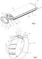
- the figure 3 also represents in 3D view the routing of the cable along the housing. In this view, only a portion of the components of the actuator is shown. In particular, the cover 33 is not shown for clarity of the drawing.
- the case is also represented on the figures 4 and 5 . It comprises a hollow main body 30, one-piece and generally cylindrical outer shape with elliptical base.
- the body 30 could also be circular.
- the body 30 defines an inner housing L 1 in which are received the motor unit 21, the unit 22 and the member 23, as well as electrical conductors not shown. Part of the motor unit 21 and the power supply unit 22, in particular the corresponding printed circuits, can be maintained in slides 31 provided on the inner faces of the body 30.
- the housing L 1 is isolated from the outside by the body 30 and the parts which seal at its ends. The materials present in this housing are therefore protected from mechanical aggression and / or ambient humidity.
- the housing L 2 is delimited only between the parts 30 and 33, which is of great simplicity of embodiment and provides a good seal.
- the hollow body has an elliptical-shaped overall section, one of whose sides of small radius of curvature A is truncated.
- the complement B of the elliptical section is made using a cover 33 whose section completes the truncated ellipse.
- the cover 33 may be termed longitudinal insofar as it extends over the corresponding length of the body 30 of the housing 20.
- the truncation of the body 30 at the side A produces a longitudinal trough 34 which extends over the entire length of the body 30.
- the cover 33 hides the access to the chute 34 vis-à-vis the outside.
- a wall 35, integral with the body 30, separates the chute 34 from the housing L 1 .
- the chute 34 thus forms a second housing L 2 which is inside the housing 20, which extends over the entire length of the body 30 and the lid 33 isolates from the outside.
- the cable 28 is received in this housing L 2 on the height of the body 30, which allows it to connect a zone Z 1 close to the unit 22, inside the housing L 1 , to a zone Z 2 in which is positioned the supply terminal 14, outside the actuator 13.
- the wall 35 is pierced with an opening 35a for the passage of the cable 28 between the housings L 1 and L 2 .
- the anti-traction ring 29 is immobilized in this opening.
- the opening 35a may be constituted by a cutout of the wall 35 which opens at one end of the body 30, which facilitates the establishment of the ring 29. This is however not mandatory and the opening 35a may be arranged at any point on the wall 35.
- the cover 33 may be made of the same material as the body 30, but it may also be made of another material, for example plastic when the body 30 is metallic.
- the cover 33 can be cut into several parts or pierced along its height to allow an output of the cable 28 at any height of the housing.
- the lid is removably mounted on the body 30.
- the lid comprises two lateral slides 36 and 37. It can have elastic properties so as to be inserted by exerting a slight deformation force allowing it to come to lock in slides 38 and 39 of corresponding shapes formed on the body 30. It can alternatively be inserted by sliding from one end of the body 30.
- the cover 33 and / or the body 30 of the housing 20 comprises, in particular at the means 36 to 39 for fixing the cover, means for holding a dressing element of the housing which is not shown.
- This covering element may be a fabric coming from covering the body of the case, this fabric being matched or identical to the curtain of the installation.
- a fabric may be wedged between the slides 36 and 38, on the one hand, 37 and 39, on the other hand over the length of the lid 33.
- This housing configuration allows the passage of the power supply cable 28 to the mains voltage (230V) safely, out of access of a user and separately from the main elements of the actuator 13 which are the engine block 21 and the power supply unit 22.
- the power supply terminal 14 is located at a false ceiling, the power cable is guided along the housing towards the top thereof.
- the power supply terminal 14 may conversely be located towards the bottom of the installation. It is then preferable to extend the cable down the actuator, which is possible because the housing L 2 opens at the bottom of the housing 20.
- the cover 33 may be provided with weak areas to create, by localized cutting of the cover 33, a passage opening of the cable 28, for example in the case where the power supply terminal 14 is located at half height of the actuator 13.
- the housing L 2 formed by the trough 34 and its cover 33 thus makes it possible to configure the actuator 13 in its most suitable form for on-site installation.
- the housing 20 also comprises, at one end of the hollow body 30, a base 40 supporting at least a portion of the feed unit 22 and / or the engine block 21.
- This base is recessed, in the form of a bowl, and closed, opposite the body 30, by a cover or plug 41 removable.
- the base 40 penetrates at least partly into the hollow body 30 when the housing 20 is assembled.
- the base 40 can slide out of the housing body to provide easy access to the power supply unit 22.
- a cover or removable cap 41 ' is attached to the body 30, opposite the base 40.
- the cover 41' is shown only to figures 2 and 3 .
- the figure 6 represents a bottom view of the actuator, when the cover 41 is removed.
- the base 40 is fixed to the body 30 of the housing, removably for example by screws 42.
- Note 43 the base of the base plate 40, this web being perpendicular to the height of the housing 20, that is, ie to the slides 31, 38 and 39 in mounted configuration of the base 40 on the body 30.
- This web supports, on one of its faces, at least a portion of the unit 22 and / or the engine block 21.
- the base 40 supports a panel 45 for controlling and configuring the actuator 13, this panel comprising adjusting knobs 46 (SET.MODE) as well as light-emitting diodes 47 for controlling. It also supports a connector RJ9 type 48 (type connector for telephone cable), it is used for connection with a cable TBT (low voltage) control to a dry contact or an interface with other systems of control not shown, outside the housing 20.
- SET.MODE adjusting knobs 46
- RJ9 type 48 type connector for telephone cable
- the cable TBT can also run inside the housing L 2 of the housing, when it is advisable to connect this cable to the top of the housing 20.
- the base 40 is partly hollow or “recessed” and defines a cavity 49 in which is received an electronic control module 50.
- This control module 50 can be adapted for different versions of the actuator 13 and thus include an infra-red receiver, a radio receiver, another connector for dry contact to allow individual and general control, or a connector of another type, for example RS485 for connection to a control bus.
- the cavity 49 forms a second housing L ' 2 , interior to the housing 20 and which is separated from the housing L 1 by the base web 43.
- Access to the control module 50 is generally hidden by the cover 41 when it is placed on the base 40.
- the cover 41 and / or the base itself 40 comprises a not shown zone of lower mechanical strength to create a passage for the power cable 28 or TBT control cable when it is necessary or better adapted to pass the cables down the actuator 13.
- the cover 41 hermetically closes the body 30 of the housing in its lower part.
- the cover 41 is removably mounted on the base 40, for example clipped or screwed, so as to make accessible the control panel 48 and configuration and / or the module 50 when necessary.
- the control module 50 is thus easily interchangeable.
- the base 40 protects the user by separating a relatively high current supply area (mains supply) from a supply area TBT.
Landscapes
- Power-Operated Mechanisms For Wings (AREA)
- Curtains And Furnishings For Windows Or Doors (AREA)
- Operating, Guiding And Securing Of Roll- Type Closing Members (AREA)
Claims (15)
- Elektromechanische Betätigungseinrichtung (13) zum Bewegen eines Schiebevorhangs (11) entlang einer Achse (X10), wobei diese Betätigungseinrichtung einen zu einem Motorblock (21) gehörenden Motor (24), eine Einheit (22) zur Energieversorgung des Motors und ein Gehäuse (20) umfasst, wobei der Motorblock (21) in einer ersten inneren Aufnahme (L1) des Gehäuses (20) aufgenommen ist, wobei das Gehäuse (20) langgestreckt ist und einen hohlen Hauptkörper (30) umfasst, der die erste innere Aufnahme (L1) definiert, die durch den Hauptkörper (30) und durch Teile, die sie an ihren Enden verschließen, nach außen isoliert ist, wobei ein Teil des Motorblocks (21), darunter die entsprechenden gedruckten Schaltungen, in der ersten inneren Aufnahme (L1) aufgenommen sind, wobei das Gehäuse (20) wenigstens eine zweite innere Aufnahme bildet, die von der ersten inneren Aufnahme durch eine Wand (35, 43) des Gehäuses getrennt ist und in der eine elektrische oder elektronische Komponente (28, 50) der Betätigungseinrichtung (13) aufgenommen ist, die sich von dem Motor (24) und der Energieversorgungseinheit (22) unterscheidet, wobei ein Deckel (33, 41) die oder jede zweite Aufnahme (L2, L'2) gegenüber dem Äußeren des Gehäuses isoliert, dadurch gekennzeichnet, dass die Energieversorgungseinheit (22) in der inneren Aufnahme (L1) aufgenommen ist und dass der Deckel (33, 41) in Bezug auf den Hauptkörper (30) abnehmbar ist.
- Betätigungseinrichtung nach Anspruch 1, dadurch gekennzeichnet, dass die erste Aufnahme (L1) und die zweite innere Aufnahme (L2) im Inneren des Hauptkörpers (30) des Gehäuses gebildet sind.
- Betätigungseinrichtung nach Anspruch 2, dadurch gekennzeichnet, dass die zweite innere Aufnahme (L2) durch einen länglichen Kanal (34) gebildet ist, der im Hauptkörper (30) geformt ist.
- Betätigungseinrichtung nach einem der vorhergehenden Ansprüche, dadurch gekennzeichnet, dass die zweite Aufnahme (L2) einerseits durch einen hohlen Hauptkörper (30) des Gehäuses (20), der die erste Aufnahme (L1) bildet, und andererseits durch den abnehmbaren Deckel (33) begrenzt wird.
- Betätigungseinrichtung nach einem der vorhergehenden Ansprüche, dadurch gekennzeichnet, dass die zweite Aufnahme (L2) wenigstens einen Abschnitt eines Energieversorgungskabels (28) aufnimmt, der sich zwischen einem in der Nähe der Energieversorgungseinheit (22) befindlichen Bereich (Z1) des Gehäuses und einem von dieser Einheit entfernten Bereich (Z2) erstreckt.
- Betätigungseinrichtung nach dem vorhergehenden Anspruch, dadurch gekennzeichnet, dass die Wand (35) mit einer Öffnung (35a) zum Durchlass des Energieversorgungskabels (28) zwischen der ersten Aufnahme (L1) und der zweiten Aufnahme (L2) versehen ist.
- Betätigungseinrichtung nach dem vorhergehenden Anspruch, dadurch gekennzeichnet, dass das Energieversorgungskabel (28) durch einen Zugentlastungsring (29) verläuft, der auf der Ebene der Öffnung (35a) der Wand (35) angebracht ist.
- Betätigungseinrichtung nach einem der vorhergehenden Ansprüche, dadurch gekennzeichnet, dass der Deckel (33) durch zwei Reihen von Gleitschienen (36-39) an einem Hauptkörper (30) des Gehäuses (20) montiert ist, der die erste innere Aufnahme (L1) definiert.
- Betätigungseinrichtung nach einem der vorhergehenden Ansprüche, dadurch gekennzeichnet, dass der Deckel (33) und/oder ein Hauptkörper (30) des Gehäuses (20), der die erste innere Aufnahme (L1) definiert, Mittel zum Halten eines Verkleidungselements des Gehäuses umfasst.
- Betätigungseinrichtung nach einem der vorhergehenden Ansprüche, dadurch gekennzeichnet, dass der äußere Querschnitt des Gehäuses (20) eine äußere geometrische Form ohne abrupten Bruch der Neigung oder des Winkels aufweist.
- Betätigungseinrichtung nach einem der vorhergehenden Ansprüche, dadurch gekennzeichnet, dass das Gehäuse (20) einen abnehmbaren Sockel (40) umfasst, wobei dieser Sockel eine Auflage für die Energieversorgungseinheit (22) und/oder für den Motor (24) bildet.
- Betätigungseinrichtung nach dem vorhergehenden Anspruch, dadurch gekennzeichnet, dass der abnehmbare Sockel (40) eine Tafel (48) zum Steuern und Konfigurieren der Betätigungseinrichtung (13) umfasst.
- Betätigungseinrichtung nach einem der Ansprüche 11 oder 12, dadurch gekennzeichnet, dass die zweite innere Aufnahme (L'2) durch den abnehmbaren Sockel (40) gebildet ist, der an einem Ende eines Hauptkörpers (30) des Gehäuses (20) montiert ist, der die erste innere Aufnahme (L1) definiert, und dass ein elektronisches Modul (50) zum Steuern der Betätigungseinrichtung (13) in der zweiten Aufnahme (L'2) aufgenommen ist.
- Betätigungseinrichtung nach den Ansprüchen 2 und 13, dadurch gekennzeichnet, dass sich eine zweite innere Aufnahme (L2) entlang des Hauptkörpers (30) erstreckt und einen Abschnitt eines Kabels (28) zur Energieversorgung der Elemente aufnimmt, die in der ersten Aufnahme aufgenommen sind, und dass eine andere zweite innere Aufnahme (L'2), die durch den abnehmbaren Sockel (40) definiert wird, ein elektronisches Modul (50) zum Steuern der Betätigungseinrichtung (13) aufnimmt.
- Betätigungseinrichtung nach einem der vorhergehenden Ansprüche, dadurch gekennzeichnet, dass der Deckel (33, 41) einen Bereich mit geringerer mechanischer Festigkeit umfasst, so dass er ausgeschnitten werden kann und einen Kabeldurchlass bilden kann.
Applications Claiming Priority (1)
| Application Number | Priority Date | Filing Date | Title |
|---|---|---|---|
| FR0857800A FR2938413B1 (fr) | 2008-11-17 | 2008-11-17 | Actionneur de manoeuvre d'un rideau coulissant |
Publications (2)
| Publication Number | Publication Date |
|---|---|
| EP2186452A1 EP2186452A1 (de) | 2010-05-19 |
| EP2186452B1 true EP2186452B1 (de) | 2018-04-18 |
Family
ID=40791618
Family Applications (1)
| Application Number | Title | Priority Date | Filing Date |
|---|---|---|---|
| EP09176040.5A Active EP2186452B1 (de) | 2008-11-17 | 2009-11-16 | Betätigungseinrichtung für einen Gleitvorhang |
Country Status (3)
| Country | Link |
|---|---|
| US (1) | US8564162B2 (de) |
| EP (1) | EP2186452B1 (de) |
| FR (1) | FR2938413B1 (de) |
Families Citing this family (11)
| Publication number | Priority date | Publication date | Assignee | Title |
|---|---|---|---|---|
| EP2609838A1 (de) * | 2010-08-26 | 2013-07-03 | Shigeo Ikeda | Elektrische vorhangschliessvorrichtung und vorhangschliessverfahren damit |
| US20150159430A1 (en) * | 2012-02-27 | 2015-06-11 | Dazhi Huang | Motorized Curtain and Blind Tracking Systems |
| AU2013227101B2 (en) * | 2012-02-27 | 2016-05-05 | Tachikawa Corporation | Motor unit of electric sun shading device and method for assembling motor unit of electric sun shading device |
| US8931541B2 (en) | 2012-03-16 | 2015-01-13 | Lutron Electronics Co., Inc. | Motorized drive unit assembly for a shade system |
| WO2014169093A1 (en) * | 2013-04-11 | 2014-10-16 | Qmotion Incorporated | Motorized drapery apparatus, system and method of use |
| US20140224439A1 (en) * | 2013-02-08 | 2014-08-14 | Beme International, Llc | Reversible bracket mounting system for window treatment support apparatus |
| US10285527B2 (en) * | 2013-07-19 | 2019-05-14 | Current Products Corp. | Motorized drapery apparatus with batteries positioned in the brackets |
| CN104643873B (zh) * | 2013-11-22 | 2017-05-17 | 雅霖工业股份有限公司 | 电动滑轨结构及其组装方法 |
| JP6518396B2 (ja) * | 2015-07-31 | 2019-05-22 | 立川ブラインド工業株式会社 | 電動遮蔽装置 |
| CN108294588B (zh) * | 2018-03-12 | 2023-09-08 | 杭州威仕达机电科技有限公司 | 开合帘轨道拼接结构 |
| US12123457B2 (en) | 2020-06-03 | 2024-10-22 | Current Products Company, LLC | Splice connector system for architectural covering support rods |
Citations (2)
| Publication number | Priority date | Publication date | Assignee | Title |
|---|---|---|---|---|
| US6062290A (en) * | 1998-02-27 | 2000-05-16 | Harmonic Design, Inc. | Photocell mounting apparatus for vertical blinds |
| US20060071619A1 (en) * | 2004-10-05 | 2006-04-06 | Vrielink Gerritt J | Modular motor converter for window covering systems |
Family Cites Families (10)
| Publication number | Priority date | Publication date | Assignee | Title |
|---|---|---|---|---|
| GB1011823A (en) * | 1961-08-07 | 1965-12-01 | Robert Addison Gill | Improvements in and relating to actuators for opening and closing curtains or like closure members |
| US5500972A (en) * | 1994-11-07 | 1996-03-26 | Foster; David C. | Rotating back scrubber |
| US5889377A (en) * | 1996-08-27 | 1999-03-30 | Mao; Kai Ming | Drapery actuator |
| CH692270A5 (de) | 1997-09-25 | 2002-04-30 | Bratschi Silent Gliss | Betätigungseinrichtung für einen Vorhang. |
| CN2398765Y (zh) * | 1999-08-13 | 2000-09-27 | 金星(礼品)有限公司 | 密封型电动机装置 |
| NL1019467C2 (nl) * | 2001-12-03 | 2003-06-04 | Rolf Edward Goelst | Inrichting voor het automatisch bewegen van een gordijn langs een gordijnrail. |
| US6935403B2 (en) * | 2002-01-02 | 2005-08-30 | Lutron Electronics Co., Inc. | Motorized drapery pull system |
| FR2842859B1 (fr) | 2002-07-25 | 2006-01-20 | Somfy | Dispositif de protection solaire motorise comprenant un moyen de guidage du cable d'alimentation du moteur |
| US7414337B2 (en) * | 2005-03-14 | 2008-08-19 | Black & Decker Inc. | Scrubber |
| US7337825B1 (en) * | 2005-07-18 | 2008-03-04 | J. Ralph Erbe | System to open and close drapes |
-
2008
- 2008-11-17 FR FR0857800A patent/FR2938413B1/fr not_active Expired - Fee Related
-
2009
- 2009-11-13 US US12/618,658 patent/US8564162B2/en active Active
- 2009-11-16 EP EP09176040.5A patent/EP2186452B1/de active Active
Patent Citations (2)
| Publication number | Priority date | Publication date | Assignee | Title |
|---|---|---|---|---|
| US6062290A (en) * | 1998-02-27 | 2000-05-16 | Harmonic Design, Inc. | Photocell mounting apparatus for vertical blinds |
| US20060071619A1 (en) * | 2004-10-05 | 2006-04-06 | Vrielink Gerritt J | Modular motor converter for window covering systems |
Also Published As
| Publication number | Publication date |
|---|---|
| FR2938413A1 (fr) | 2010-05-21 |
| EP2186452A1 (de) | 2010-05-19 |
| US20100122781A1 (en) | 2010-05-20 |
| FR2938413B1 (fr) | 2012-03-16 |
| US8564162B2 (en) | 2013-10-22 |
Similar Documents
| Publication | Publication Date | Title |
|---|---|---|
| EP2186452B1 (de) | Betätigungseinrichtung für einen Gleitvorhang | |
| EP1090788B1 (de) | Anordnung mit einer inneren Auskleidung einer Fahrzeugtür und einem Fensterhebermechanismus befestigt an dieser Auskleidung | |
| EP2862259B1 (de) | Motorantrieb für die bedienung eines schutzschirms wie eine fensterabdeckung oder einer projektionsleinwand | |
| EP4136309B1 (de) | Verdunkelungsvorrichtung | |
| CA2875163A1 (fr) | Ensemble d'affichage lumineux a pinces de suspension | |
| FR2852811A1 (fr) | Aspirateur autonome bimoteur | |
| EP3857014A1 (de) | Elektromechanischer aktuator mit einem modul zur filterung von vibrationen und verschluss, abdeckung oder sonnenschutzsystem mit einem solchen elektromechanischen aktuator | |
| EP1914770B1 (de) | Vorrichtung zur Positionserfassung zweier Elemente zueinander zum verbesserten Einbau | |
| FR2743532A1 (fr) | Structure d'installation et procede d'assemblage d'elements de porte de vehicule | |
| FR2855748A1 (fr) | Canne pour personne ayant un handicap moteur | |
| WO2008129186A2 (fr) | Store vénitien pour baies vitrées | |
| EP1971797B1 (de) | Vorrichtung zum schutz und zur führung eines kabels eines öffenbaren fensters einer flugzeugkabine | |
| EP1636450B1 (de) | Betätigungsvorrichtung zum öffnen einer tür | |
| FR3133883A1 (fr) | Dispositif d’entraînement motorisé d’un dispositif d’occultation et dispositif d’occultation associé | |
| BE1023588B1 (fr) | Porte formee d'un bati et d'un vantail dote d'un dispositif d'eclairage | |
| FR2845109A1 (fr) | Dispositif de verrouillage de porte a commande mecanique et electriques, notamment porte de boite aux lettres | |
| WO2010100072A1 (fr) | Ensemble comprenant une poignee et un panneau d' un ouvrant de vehicule automobile | |
| FR2968347A1 (fr) | Dispositif d'occultation coulissant autotracte | |
| FR2706015A1 (fr) | Palier de retenue d'une tablette amovible sur un support. | |
| FR3054261A1 (fr) | Agencement automatique de vantaux coulissants | |
| FR3152037A1 (fr) | Actionneur électromécanique d’un dispositif d’occultation et dispositif d’occultation comprenant un tel actionneur électromécanique | |
| EP3835538A1 (de) | Elektromechanisches stellglied, das ein aufhängungsorgan umfasst, und schliess- oder sonnenschutzanlage, die ein solches elektromechanisches stellglied umfasst | |
| EP3996121A1 (de) | Steuerungs- und/oder signalhilfsmittel, das an seinem montageumfang zugänglich ist und verfahren zur montage auf einem rohrförmigen träger | |
| EP2312545B1 (de) | Bewegungsmelder mit beweglicher Abdeckung | |
| FR3154433A1 (fr) | Dispositif d’occultation comprenant un dispositif d’entraînement motorisé |
Legal Events
| Date | Code | Title | Description |
|---|---|---|---|
| PUAI | Public reference made under article 153(3) epc to a published international application that has entered the european phase |
Free format text: ORIGINAL CODE: 0009012 |
|
| AK | Designated contracting states |
Kind code of ref document: A1 Designated state(s): AT BE BG CH CY CZ DE DK EE ES FI FR GB GR HR HU IE IS IT LI LT LU LV MC MK MT NL NO PL PT RO SE SI SK SM TR |
|
| 17P | Request for examination filed |
Effective date: 20101027 |
|
| 17Q | First examination report despatched |
Effective date: 20151221 |
|
| GRAP | Despatch of communication of intention to grant a patent |
Free format text: ORIGINAL CODE: EPIDOSNIGR1 |
|
| INTG | Intention to grant announced |
Effective date: 20171124 |
|
| RAP1 | Party data changed (applicant data changed or rights of an application transferred) |
Owner name: SOMFY ACTIVITES SA |
|
| GRAS | Grant fee paid |
Free format text: ORIGINAL CODE: EPIDOSNIGR3 |
|
| GRAA | (expected) grant |
Free format text: ORIGINAL CODE: 0009210 |
|
| AK | Designated contracting states |
Kind code of ref document: B1 Designated state(s): AT BE BG CH CY CZ DE DK EE ES FI FR GB GR HR HU IE IS IT LI LT LU LV MC MK MT NL NO PL PT RO SE SI SK SM TR |
|
| REG | Reference to a national code |
Ref country code: GB Ref legal event code: FG4D Free format text: NOT ENGLISH |
|
| REG | Reference to a national code |
Ref country code: CH Ref legal event code: EP |
|
| REG | Reference to a national code |
Ref country code: AT Ref legal event code: REF Ref document number: 989505 Country of ref document: AT Kind code of ref document: T Effective date: 20180515 |
|
| REG | Reference to a national code |
Ref country code: IE Ref legal event code: FG4D Free format text: LANGUAGE OF EP DOCUMENT: FRENCH |
|
| REG | Reference to a national code |
Ref country code: DE Ref legal event code: R096 Ref document number: 602009051822 Country of ref document: DE |
|
| REG | Reference to a national code |
Ref country code: NL Ref legal event code: FP |
|
| REG | Reference to a national code |
Ref country code: LT Ref legal event code: MG4D |
|
| REG | Reference to a national code |
Ref country code: FR Ref legal event code: PLFP Year of fee payment: 10 |
|
| PG25 | Lapsed in a contracting state [announced via postgrant information from national office to epo] |
Ref country code: ES Free format text: LAPSE BECAUSE OF FAILURE TO SUBMIT A TRANSLATION OF THE DESCRIPTION OR TO PAY THE FEE WITHIN THE PRESCRIBED TIME-LIMIT Effective date: 20180418 Ref country code: SE Free format text: LAPSE BECAUSE OF FAILURE TO SUBMIT A TRANSLATION OF THE DESCRIPTION OR TO PAY THE FEE WITHIN THE PRESCRIBED TIME-LIMIT Effective date: 20180418 Ref country code: NO Free format text: LAPSE BECAUSE OF FAILURE TO SUBMIT A TRANSLATION OF THE DESCRIPTION OR TO PAY THE FEE WITHIN THE PRESCRIBED TIME-LIMIT Effective date: 20180718 Ref country code: FI Free format text: LAPSE BECAUSE OF FAILURE TO SUBMIT A TRANSLATION OF THE DESCRIPTION OR TO PAY THE FEE WITHIN THE PRESCRIBED TIME-LIMIT Effective date: 20180418 Ref country code: BG Free format text: LAPSE BECAUSE OF FAILURE TO SUBMIT A TRANSLATION OF THE DESCRIPTION OR TO PAY THE FEE WITHIN THE PRESCRIBED TIME-LIMIT Effective date: 20180718 Ref country code: PL Free format text: LAPSE BECAUSE OF FAILURE TO SUBMIT A TRANSLATION OF THE DESCRIPTION OR TO PAY THE FEE WITHIN THE PRESCRIBED TIME-LIMIT Effective date: 20180418 Ref country code: LT Free format text: LAPSE BECAUSE OF FAILURE TO SUBMIT A TRANSLATION OF THE DESCRIPTION OR TO PAY THE FEE WITHIN THE PRESCRIBED TIME-LIMIT Effective date: 20180418 |
|
| PG25 | Lapsed in a contracting state [announced via postgrant information from national office to epo] |
Ref country code: GR Free format text: LAPSE BECAUSE OF FAILURE TO SUBMIT A TRANSLATION OF THE DESCRIPTION OR TO PAY THE FEE WITHIN THE PRESCRIBED TIME-LIMIT Effective date: 20180719 Ref country code: LV Free format text: LAPSE BECAUSE OF FAILURE TO SUBMIT A TRANSLATION OF THE DESCRIPTION OR TO PAY THE FEE WITHIN THE PRESCRIBED TIME-LIMIT Effective date: 20180418 Ref country code: HR Free format text: LAPSE BECAUSE OF FAILURE TO SUBMIT A TRANSLATION OF THE DESCRIPTION OR TO PAY THE FEE WITHIN THE PRESCRIBED TIME-LIMIT Effective date: 20180418 |
|
| REG | Reference to a national code |
Ref country code: AT Ref legal event code: MK05 Ref document number: 989505 Country of ref document: AT Kind code of ref document: T Effective date: 20180418 |
|
| PG25 | Lapsed in a contracting state [announced via postgrant information from national office to epo] |
Ref country code: PT Free format text: LAPSE BECAUSE OF FAILURE TO SUBMIT A TRANSLATION OF THE DESCRIPTION OR TO PAY THE FEE WITHIN THE PRESCRIBED TIME-LIMIT Effective date: 20180820 |
|
| REG | Reference to a national code |
Ref country code: DE Ref legal event code: R097 Ref document number: 602009051822 Country of ref document: DE |
|
| PG25 | Lapsed in a contracting state [announced via postgrant information from national office to epo] |
Ref country code: RO Free format text: LAPSE BECAUSE OF FAILURE TO SUBMIT A TRANSLATION OF THE DESCRIPTION OR TO PAY THE FEE WITHIN THE PRESCRIBED TIME-LIMIT Effective date: 20180418 Ref country code: CZ Free format text: LAPSE BECAUSE OF FAILURE TO SUBMIT A TRANSLATION OF THE DESCRIPTION OR TO PAY THE FEE WITHIN THE PRESCRIBED TIME-LIMIT Effective date: 20180418 Ref country code: AT Free format text: LAPSE BECAUSE OF FAILURE TO SUBMIT A TRANSLATION OF THE DESCRIPTION OR TO PAY THE FEE WITHIN THE PRESCRIBED TIME-LIMIT Effective date: 20180418 Ref country code: EE Free format text: LAPSE BECAUSE OF FAILURE TO SUBMIT A TRANSLATION OF THE DESCRIPTION OR TO PAY THE FEE WITHIN THE PRESCRIBED TIME-LIMIT Effective date: 20180418 Ref country code: DK Free format text: LAPSE BECAUSE OF FAILURE TO SUBMIT A TRANSLATION OF THE DESCRIPTION OR TO PAY THE FEE WITHIN THE PRESCRIBED TIME-LIMIT Effective date: 20180418 Ref country code: SK Free format text: LAPSE BECAUSE OF FAILURE TO SUBMIT A TRANSLATION OF THE DESCRIPTION OR TO PAY THE FEE WITHIN THE PRESCRIBED TIME-LIMIT Effective date: 20180418 |
|
| PLBE | No opposition filed within time limit |
Free format text: ORIGINAL CODE: 0009261 |
|
| STAA | Information on the status of an ep patent application or granted ep patent |
Free format text: STATUS: NO OPPOSITION FILED WITHIN TIME LIMIT |
|
| PG25 | Lapsed in a contracting state [announced via postgrant information from national office to epo] |
Ref country code: IT Free format text: LAPSE BECAUSE OF FAILURE TO SUBMIT A TRANSLATION OF THE DESCRIPTION OR TO PAY THE FEE WITHIN THE PRESCRIBED TIME-LIMIT Effective date: 20180418 Ref country code: SM Free format text: LAPSE BECAUSE OF FAILURE TO SUBMIT A TRANSLATION OF THE DESCRIPTION OR TO PAY THE FEE WITHIN THE PRESCRIBED TIME-LIMIT Effective date: 20180418 |
|
| 26N | No opposition filed |
Effective date: 20190121 |
|
| PG25 | Lapsed in a contracting state [announced via postgrant information from national office to epo] |
Ref country code: SI Free format text: LAPSE BECAUSE OF FAILURE TO SUBMIT A TRANSLATION OF THE DESCRIPTION OR TO PAY THE FEE WITHIN THE PRESCRIBED TIME-LIMIT Effective date: 20180418 |
|
| REG | Reference to a national code |
Ref country code: CH Ref legal event code: PL |
|
| PG25 | Lapsed in a contracting state [announced via postgrant information from national office to epo] |
Ref country code: LU Free format text: LAPSE BECAUSE OF NON-PAYMENT OF DUE FEES Effective date: 20181116 Ref country code: MC Free format text: LAPSE BECAUSE OF FAILURE TO SUBMIT A TRANSLATION OF THE DESCRIPTION OR TO PAY THE FEE WITHIN THE PRESCRIBED TIME-LIMIT Effective date: 20180418 |
|
| REG | Reference to a national code |
Ref country code: BE Ref legal event code: MM Effective date: 20181130 |
|
| REG | Reference to a national code |
Ref country code: IE Ref legal event code: MM4A |
|
| PG25 | Lapsed in a contracting state [announced via postgrant information from national office to epo] |
Ref country code: CH Free format text: LAPSE BECAUSE OF NON-PAYMENT OF DUE FEES Effective date: 20181130 Ref country code: LI Free format text: LAPSE BECAUSE OF NON-PAYMENT OF DUE FEES Effective date: 20181130 |
|
| PG25 | Lapsed in a contracting state [announced via postgrant information from national office to epo] |
Ref country code: IE Free format text: LAPSE BECAUSE OF NON-PAYMENT OF DUE FEES Effective date: 20181116 |
|
| PG25 | Lapsed in a contracting state [announced via postgrant information from national office to epo] |
Ref country code: BE Free format text: LAPSE BECAUSE OF NON-PAYMENT OF DUE FEES Effective date: 20181130 |
|
| PG25 | Lapsed in a contracting state [announced via postgrant information from national office to epo] |
Ref country code: MT Free format text: LAPSE BECAUSE OF FAILURE TO SUBMIT A TRANSLATION OF THE DESCRIPTION OR TO PAY THE FEE WITHIN THE PRESCRIBED TIME-LIMIT Effective date: 20180418 |
|
| PG25 | Lapsed in a contracting state [announced via postgrant information from national office to epo] |
Ref country code: TR Free format text: LAPSE BECAUSE OF FAILURE TO SUBMIT A TRANSLATION OF THE DESCRIPTION OR TO PAY THE FEE WITHIN THE PRESCRIBED TIME-LIMIT Effective date: 20180418 |
|
| PG25 | Lapsed in a contracting state [announced via postgrant information from national office to epo] |
Ref country code: HU Free format text: LAPSE BECAUSE OF FAILURE TO SUBMIT A TRANSLATION OF THE DESCRIPTION OR TO PAY THE FEE WITHIN THE PRESCRIBED TIME-LIMIT; INVALID AB INITIO Effective date: 20091116 Ref country code: MK Free format text: LAPSE BECAUSE OF NON-PAYMENT OF DUE FEES Effective date: 20180418 Ref country code: CY Free format text: LAPSE BECAUSE OF FAILURE TO SUBMIT A TRANSLATION OF THE DESCRIPTION OR TO PAY THE FEE WITHIN THE PRESCRIBED TIME-LIMIT Effective date: 20180418 |
|
| PG25 | Lapsed in a contracting state [announced via postgrant information from national office to epo] |
Ref country code: IS Free format text: LAPSE BECAUSE OF FAILURE TO SUBMIT A TRANSLATION OF THE DESCRIPTION OR TO PAY THE FEE WITHIN THE PRESCRIBED TIME-LIMIT Effective date: 20180818 |
|
| PGFP | Annual fee paid to national office [announced via postgrant information from national office to epo] |
Ref country code: NL Payment date: 20241029 Year of fee payment: 16 |
|
| PGFP | Annual fee paid to national office [announced via postgrant information from national office to epo] |
Ref country code: GB Payment date: 20241122 Year of fee payment: 16 |
|
| PGFP | Annual fee paid to national office [announced via postgrant information from national office to epo] |
Ref country code: FR Payment date: 20250929 Year of fee payment: 17 |
|
| PGFP | Annual fee paid to national office [announced via postgrant information from national office to epo] |
Ref country code: DE Payment date: 20251117 Year of fee payment: 17 |