EP2186476A2 - Durchflussmesser für Lungenfunktionstests - Google Patents
Durchflussmesser für Lungenfunktionstests Download PDFInfo
- Publication number
- EP2186476A2 EP2186476A2 EP09176199A EP09176199A EP2186476A2 EP 2186476 A2 EP2186476 A2 EP 2186476A2 EP 09176199 A EP09176199 A EP 09176199A EP 09176199 A EP09176199 A EP 09176199A EP 2186476 A2 EP2186476 A2 EP 2186476A2
- Authority
- EP
- European Patent Office
- Prior art keywords
- measuring tube
- offtake
- pressure
- adapter unit
- stubs
- Prior art date
- Legal status (The legal status is an assumption and is not a legal conclusion. Google has not performed a legal analysis and makes no representation as to the accuracy of the status listed.)
- Withdrawn
Links
Images

Classifications
-
- A—HUMAN NECESSITIES
- A61—MEDICAL OR VETERINARY SCIENCE; HYGIENE
- A61B—DIAGNOSIS; SURGERY; IDENTIFICATION
- A61B5/00—Measuring for diagnostic purposes; Identification of persons
- A61B5/08—Measuring devices for evaluating the respiratory organs
- A61B5/087—Measuring breath flow
-
- G—PHYSICS
- G01—MEASURING; TESTING
- G01F—MEASURING VOLUME, VOLUME FLOW, MASS FLOW OR LIQUID LEVEL; METERING BY VOLUME
- G01F1/00—Measuring the volume flow or mass flow of fluid or fluent solid material wherein the fluid passes through a meter in a continuous flow
- G01F1/05—Measuring the volume flow or mass flow of fluid or fluent solid material wherein the fluid passes through a meter in a continuous flow by using mechanical effects
- G01F1/34—Measuring the volume flow or mass flow of fluid or fluent solid material wherein the fluid passes through a meter in a continuous flow by using mechanical effects by measuring pressure or differential pressure
- G01F1/36—Measuring the volume flow or mass flow of fluid or fluent solid material wherein the fluid passes through a meter in a continuous flow by using mechanical effects by measuring pressure or differential pressure the pressure or differential pressure being created by the use of flow constriction
- G01F1/40—Details of construction of the flow constriction devices
- G01F1/46—Pitot tubes
Definitions
- the invention relates to a flow meter for pulmonary function tests, in particular to a Pitot tube flow metering device for pulmonary function tests.
- a class of apparatuses for pulmonary function tests is constituted by devices of direct construction (e.g. spirometers, rhinomanometers, whole body plethysmographs, diffusing capacity meters, ergospirometers) that involve a flow meter as the primary measuring transducer.
- Various means/techniques such as e.g. means and processes based on the detection of change in ultrasonic waves or equipments and techniques based on the pressure difference measurements in various geometrical arrangements (i.e. employing different flow resistances) are made use of as the flow meter and/or to meter the air stream (induced, in general, by the respiration of the individual examined) flowing through the apparatus.
- the Pitot or Prandtl tube equipments used to determine the difference between the static and stagnation pressures induced by an air stream are, in particular, based on a pressure difference measurement.
- the essence of such an equipment is that a double-wall probe is arranged, generally, within the measuring tube, by means of which the static and stagnation pressures created by the flow stream can be simultaneously measured. Then, based on Bernoulli's law, the magnitude of the unknown flow rate can be unambiguously determined.
- the general advantage of the Pitot or Prandtl tube equipments their relatively simple construction, small dead space and low flow resistance can be mentioned. Their great disadvantages are, however, that the useful signal generated by them is relatively noisy (i.e. in this case the signal-to-noise ratio influencing the precision and reliability of the measurement is not satisfactory) and/or their characteristics is nonlinear (quadratic).
- U.S. Patent No. 5,088,322 discloses an averaging Pitot tube flow measuring device for the measurement of a gas flow, in particular, a gas flow emerging due to exhalation/inhalation.
- Pressure lead-out elements of the Pitot tube are made in the form of radial pressure offtake vanes at the angle of 120° to one another.
- the surface of said vanes which is in contact with the gas flowing through the measuring tube is provided with channels suitable for leading away stagnation pressure.
- the channels extend along the full length of each vane, specifically from the inner surface of the wall of the measuring tube to an aperture located on the longitudinal axis of said measuring tube. Accordingly, for a certain vane, the averaging of pressure values takes place radially from the center of the measuring tube to the wall thereof.
- vanes in which they are at the angle of 120° to one another enables the averaging of pressure values along the directions X and Y as well (here and from now on, direction Z corresponds to the direction parallel with the longitudinal axis of the measuring tube). Transmission of the pressure signal to a transducer arranged outside of the measuring tube takes place through said central aperture.
- the vane surfaces provided with channels are located in a plane perpendicular to the longitudinal axis of the measuring tube.
- the vane surfaces extending from the inner surface of the measuring tube to the axis of symmetry thereof incline in the radial direction.
- 5,088,332 is apt for measuring flow rates of either direction (i.e. in case of either exhalation or inhalation; symmetric construction). Said flow meter can also be used to analyze the gas composition flowing through the measuring tube. An outlet for the analysis of the gas composition is located symmetrically with respect to the central pressure offtake aperture, that is the measurement of both the pressure and the gas composition can be performed under the same conditions even if the flowing is of opposite direction.
- the major disadvantage of said flow meter is that the pressure offtake aperture is located just at the geometrical center of the measuring tube, wherein the flow rate is the highest. Consequently, the risk of being contaminated by the minute moisture and/or the drops of sputum exhaled with air through getting into the offtake aperture is also the highest just at this point.
- an appropriate filtering member is always incorporated into the total respiratory circuit when it is actually used for this purpose.
- the flow meter according to U.S. Patent No. 5,088,332 is suitable for pulmonary function tests only in a limited manner.
- a surface coating capable of adsorbing water is optionally applied onto the vanes.
- This, as well as the coating applied itself increase the production costs of said flow meter.
- the coating used encumbers significantly the recycling of the contaminated measuring tube.
- WO 03/047429 teaches a symmetric and averaging Pitot tube respiratory flow metering device, as well as various pressure averaging techniques.
- the Pitot tube is realized with a sensing tube arranged within a measuring tube, wherein said sensing tube is perpendicular to the direction of flow and crosses the longitudinal axis of said flow metering device. Sampling of pressure takes place through sensing bores formed on the sensing tube at its given points along the direction of the radius of the measuring tube.
- a disadvantage of said flow metering device is that it is apt for averaging only along one of the directions X and Y at a time.
- sensing tube cannot be removed together with the measuring tube after every single measurement and, hence, there is a possibility of cross infection between individuals examined one after the other if disinfection of said device is inappropriate.
- a further disadvantage of the flow metering device concerned is that the sensing bores used for the sampling get easily clogged (because of their sizes) due to the moisture and/or sputum content of the exhaled air. This holds especially for diagnostic inspections of the lung.
- the flow meter head according to Polish Patent No. 173,767 also represents essentially a symmetric and averaging Pitot tube flow metering device.
- a disadvantage of said device is that the aerodynamical resistance forming a part thereof only measures a vertical segment of the flow traveling through the measuring tube, that is, it averages only along a single direction.
- Another disadvantage of the device concerned is that the channels within said resistance directly guide the moisture/sputum condensing within the measuring tube into the pressure gauge sensing means.
- U.S. Patent No. 5,038,773 discloses a further symmetric and averaging Pitot tube flow metering device that is basically made use of as a disposable flow meter.
- bores for pressure sampling are formed in the ends of two ribs located in the vicinity of the inner surface of the measuring tube wherein said ribs are crossing each other and arranged in the path of flow within said measuring tube.
- said bores can easily be clogged by the moisture and/or sputum content of the exhaled air due to their small cross sections.
- a further disadvantage of said flow metering device is that the pressure sensing bores formed in the vicinity of the ends of the ribs do not enable radial averaging.
- U.S. Patent No. 5,048,327 teaches a Venturi tube gas flow metering device to be used for governing the fuel injection system of internal combustion engines, wherein the signal-to-noise ratio of the difference signal of a high pressure and a low pressure is increased by means of a low-pass pneumatic filtering arrangement.
- said high pressure is guided through a conduit representing a flow resistance R and a ring-shaped reservoir representing a capacitance C, filtering out the pressure fluctuations present in the high pressure thereby.
- Said U.S. patent is expressedly limited to Venturi tube flow meters, the applicability of a low-pass pneumatic filtering arrangement in other type of flow meters is not mentioned (and is not even hinted at).
- said document contains no teaching as to the adaptation of said filtering arrangement for flow meters based on other principles.
- the aim of the present invention is to provide a flow metering device eliminating or at least reducing the disadvantages of the Pitot tube flow meters discussed.
- the present invention aims at providing a Pitot tube flow metering device for pulmonary function tests that is of a simple construction, compact and optionally also disposable, and which is capable of enhancing the signal-to-noise ratio of the measured pressure signals through the application of no electronic components, as well as in the vicinity of the place of generation of said pressure signals.
- a yet further object of the present invention is to provide a flow metering device for pulmonary function tests that tends to get contaminated up to a smaller extent than the devices discussed earlier and at the same time it is also apt for an averaging along a radial direction in the flow cross section besides the averaging completed along the directions X and Y.
- a yet further object of the present invention is to provide a flow metering device of small dead space for pulmonary function tests that provides a precise flow metering with low flow resistance in a broad range of flow and along with a low risk of cross infection.
- a yet further object of the present invention is to manufacture a flow metering device that can optionally be recycled in a simple and cost effective manner.
- FIGS 1 and 2 illustrate a possible embodiment 10 of the flow metering device according to the invention in various views.
- the flow metering device 10 comprises a pneumatic adapter unit 12 and a measuring tube 14 connectable to the adapter unit 12 by a single movement in a detachable, but pressure tight manner.
- Said detachable connection forms by inserting pressure signal offtake stubs 18, 28 with channels 18a, 28a, respectively, of the measuring tube 14 into reception bores 16, 26 formed in said adapter unit 12.
- the pressure tight closure is accomplished by sealing members 19, provided preferably in the form of O-rings, placed preferably in said reception bores 16, 26.
- the measuring tube 14 of the flow metering device 10 can simply and rapidly be disconnected from the adapter unit 12 and replaced by a further (e.g. sterile) measuring tube.
- the measuring tube 14 detached in this way might be prepared for a subsequent usage by means of sterilizing or can simply be destroyed as dangerous waste.
- the flow metering device according to the invention ensures prevention of both the cross infections between patients and the device getting infectious (and/or contaminated).
- the flow metering device 10 for pulmonary function tests is basically a symmetric and averaging Pitot tube device.
- a spoke 20 forming a pressure offtake element is arranged within the measuring tube 14 of given length, essentially at about the half of said length.
- said spoke 20 is formed by three spoke arms that are essentially perpendicular to the longitudinal axis of the measuring tube 14 and extend radially to the inner surface of the wall of said measuring tube 14.
- each spoke arm is of an approximate guttiform in cross section.
- the spoke arms are equal in length and join at the angle of 120° to one another in such a way that said spoke 20 is symmetric with respect to a plane that is incident to the longitudinal axis of the measuring tube 14 and parallel with the geometrical axes of said reception bores 16, 26.
- the spoke 20 can also be realized with different geometries, e.g. with more than three spoke arms, with different angles of join of the spoke arms or with various lengths of the spoke arms, and/or tilted in a small angle (preferably of at most 15°) relative to a plane perpendicular to the longitudinal axis of the measuring tube 14 (i.e. to the direction of flow).
- a requisite for suitable geometries is that the flow metering device 10 should remain apt for averaging along both independent directions in the plane perpendicular to the flow direction and, furthermore, the flow resistance should be kept at a relatively low value.
- the spoke 20 is of a given length along the direction of flow.
- pressure offtake grooves 17, 27 are formed in the end surfaces of said spoke 20 that are perpendicular to the direction of flow.
- the grooves 17, 27 start at the joint of the spoke arms, extend along each spoke arm and the spoke arms located symmetrically with respect to said plane of symmetry connect into respective through holes formed in the wall of the measuring tube 14 and thus open into the channels 18a, 28a of the pressure signal offtake stubs 18, 28.
- the grooves 17, 27 formed in the end surfaces of the third spoke arm, which is incident to said plane of symmetry, terminate at the inner surface of the wall of the measuring tube 14; no pressure signal offtake stubs are connected to them.
- the pressure offtake grooves 17, 27 correspond to the double-wall probe of a Pitot tube, play its part in a measurement, i.e. they lead away the pressure signals averaged both along the independent directions in a plane perpendicular to the direction of flow and radially from the measuring tube 14 at extreme points, that is through the wall of said measuring tube 14. As the pressure offtake grooves 17, 27 start at the middle of the measuring tube 14 and extend to the wall thereof, said grooves perform the radial averaging for the full cross section of the flow.
- the through holes receiving the pressure offtake grooves 17, 27 are formed in the wall of the measuring tube in a position so as to locate slightly higher than the lowest point of the measuring tube 14.
- said through holes are formed in the wall of the measuring tube 14 at such a height that the grooves 17, 27 close the angles of essentially 60° with the channels 18a, 28a. According to the studies performed, the risk of inflowing of the condensing moisture and/or the secretion/sputum carried by the exhaled air stream into said adapter unit 12 and thereby its contamination can be eliminated or at least significantly decreased with a construction of this type.
- each filter 15, 25 consists of two constrictions, i.e. two resistances in series, and a cavity of a relatively large volume formed within the adapter unit 12, i.e. a capacitive member in parallel.
- said filters 15, 25 filter the noisy pressure difference signal generated by the pressure offtake grooves 17, 27, as Pitot tubes, and transmitted via the channels 18a, 28a of the pressure signal offtake stubs 18, 28 and thus increase the signal-to-noise ratio thereof.
- Said filtering serves for eliminating portions of the pressure signals (i.e.
- the cut-off frequency is set by the volume ratio of said constrictions and said cavity when the adapter unit 12 is fabricated.
- the cut-off frequency is set by the volume ratio of said constrictions and said cavity when the adapter unit 12 is fabricated.
- the pneumatic low-pass filters 15, 25 are connected to the channels 13a, 23a of output pressure signal offtake stubs 13, 23 that serve for transmitting the filtered pressure difference signal to a transducer (not shown in the drawing), preferentially to a differential pressure-gauge.
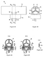
- FIGS 3A and 3B illustrate a possible further embodiment 110 of the flow metering device according to the invention.
- this embodiment is identical to the one discussed with reference to Figures 1 and 2 .
- the identical structural parts and their functions are not discussed in detail.
- a flow metering device 110 differs from the flow metering device 10 in that its measuring tube 114 is provided with at least one further gas sampling connecting stub 130 in communication with the inner volume of the measuring tube 114, while its adapter unit 112 is provided with a reception bore 136 receiving said connecting stub 130 in a detachable, but pressure tight manner, as well as a sample offtake stub 138 for transporting the sample taken out from the measuring tube 114 into a suitable analyzing means (not shown in the drawing).
- the pressure tight closure is accomplished by a sealing member 139, also provided preferably in the form of an O-ring, placed preferably into said reception bore 136.
- the gas sampling connecting stub 130 also joins to the measuring tube 114 at an angle of 60°, i.e. at a location that forms not the lowest point of said measuring tube 114. According to the studies performed, the risk of inflowing of the condensing moisture and/or the secretion/sputum carried by the exhaled air stream into said adapter unit 112 and thereby its contamination can be eliminated or at least significantly decreased with a construction of this type.
- the flow metering device 110 for pulmonary function tests is also suitable for performing extended pulmonary function tests.
- Such an extended pulmonary function testing technique is e.g. the diffusing capacity measurement or ergospirometry wherein there is also a need to determine the gas composition of the exhaled and inhaled air.
- the compact Pitot tube flow metering device for pulmonary function tests ensures a precise flow metering with low flow resistance in a wide range of flow.
- the risk of cross infection is low due to the fact that said measuring tube can simply be detached from the adapter unit and hence replaced.
- the flow metering device for pulmonary function tests eliminates one of the major disadvantages of Pitot tube flow meters according to which the difference pressure signal is very noisy. Due to the inclusion of pneumatic filters, in this case there is basically no need to increase the signal-to-noise ratio electronically.
- the flow metering device for pulmonary function tests is cheap and enables a large scale mass production, making it ideally suited even to use as disposable medical device.
- both the measuring tube and the adapter unit can optionally be made of a single material (preferentially, by means of e.g. injection molding of a suitable plastic material), in lack of possibility and/or objective to sterilize the measuring tube, an already spent flow meter can simply be recycled to the full extent, thereby decreasing significantly the manufacturing and recycling costs of such type of devices.
Landscapes
- Health & Medical Sciences (AREA)
- Life Sciences & Earth Sciences (AREA)
- Physics & Mathematics (AREA)
- Medical Informatics (AREA)
- Surgery (AREA)
- Biophysics (AREA)
- Pathology (AREA)
- Engineering & Computer Science (AREA)
- Biomedical Technology (AREA)
- Heart & Thoracic Surgery (AREA)
- Physiology (AREA)
- Molecular Biology (AREA)
- Pulmonology (AREA)
- Animal Behavior & Ethology (AREA)
- General Health & Medical Sciences (AREA)
- Public Health (AREA)
- Veterinary Medicine (AREA)
- Fluid Mechanics (AREA)
- General Physics & Mathematics (AREA)
- Measurement Of The Respiration, Hearing Ability, Form, And Blood Characteristics Of Living Organisms (AREA)
- Measuring Volume Flow (AREA)
- Measuring Pulse, Heart Rate, Blood Pressure Or Blood Flow (AREA)
Applications Claiming Priority (1)
| Application Number | Priority Date | Filing Date | Title |
|---|---|---|---|
| HU0800685A HU229884B1 (hu) | 2008-11-17 | 2008-11-17 | Légzésdiagnosztikai áramlásmérõ eszköz |
Publications (2)
| Publication Number | Publication Date |
|---|---|
| EP2186476A2 true EP2186476A2 (de) | 2010-05-19 |
| EP2186476A3 EP2186476A3 (de) | 2013-03-06 |
Family
ID=89988607
Family Applications (1)
| Application Number | Title | Priority Date | Filing Date |
|---|---|---|---|
| EP09176199A Withdrawn EP2186476A3 (de) | 2008-11-17 | 2009-11-17 | Durchflussmesser für Lungenfunktionstests |
Country Status (3)
| Country | Link |
|---|---|
| US (1) | US8585608B2 (de) |
| EP (1) | EP2186476A3 (de) |
| HU (1) | HU229884B1 (de) |
Cited By (1)
| Publication number | Priority date | Publication date | Assignee | Title |
|---|---|---|---|---|
| CN107374635A (zh) * | 2017-08-17 | 2017-11-24 | 台州亿联健医疗科技有限公司 | 可防止交叉感染的肺功能仪 |
Families Citing this family (2)
| Publication number | Priority date | Publication date | Assignee | Title |
|---|---|---|---|---|
| CN112568893A (zh) * | 2019-09-27 | 2021-03-30 | 浙江亿联康医疗科技有限公司 | 用于肺功能检测的流量传感器 |
| DE102021120883A1 (de) * | 2021-08-11 | 2023-02-16 | Sick Ag | Bestimmung des Durchflusses eines strömenden Fluids |
Citations (6)
| Publication number | Priority date | Publication date | Assignee | Title |
|---|---|---|---|---|
| US5038773A (en) | 1990-06-08 | 1991-08-13 | Medical Graphics Corporation | Flow meter system |
| US5048327A (en) | 1990-05-17 | 1991-09-17 | Atwood Robert K | Mass air flow meter |
| US5088332A (en) | 1988-12-12 | 1992-02-18 | Instrumentarium Corporation | Gas flow restricting and directing device intended for flow measurement |
| US5088322A (en) | 1990-05-29 | 1992-02-18 | Equimeter, Inc. | Extended range flow meter |
| PL173767B1 (pl) | 1994-04-29 | 1998-04-30 | Andrzej Dymek | Głowica pneumotachograficzna |
| WO2003047429A1 (en) | 2001-12-05 | 2003-06-12 | Un Jong Cha | Apparatus for measuring respiratory gas flow by means of a disposable respiratory tube |
Family Cites Families (8)
| Publication number | Priority date | Publication date | Assignee | Title |
|---|---|---|---|---|
| DE3039916A1 (de) * | 1979-10-27 | 1981-05-07 | Dietmar Rudolf Buckingham Buckinghamshire Garbe | Mundstueck fuer ein spirometer-einlassrohr |
| JPS5735718A (en) * | 1980-08-12 | 1982-02-26 | Citizen Watch Co Ltd | Rectifying element |
| BG44992A1 (de) * | 1987-06-16 | 1989-03-15 | Jjordan Jj Bejazov | |
| US5450760A (en) * | 1993-10-18 | 1995-09-19 | Lew; Hyok S. | Turbine flowmeter with capacitive transducer |
| FI102918B (fi) * | 1996-07-02 | 1999-03-15 | Instrumentarium Oy | Mittausanturi ja järjestelmä kaasun virtausmittausta varten |
| FI102453B1 (fi) * | 1997-03-17 | 1998-12-15 | Instrumentarium Oy | Parannettu mittausanturi ja järjestelmä kaasun virtausmittausta varten |
| EP1228779A1 (de) * | 2001-02-01 | 2002-08-07 | Instrumentarium Corporation | Verfahren und Vorrichtung zur Bestimmung eines Null Gasflusszustandes in einer bidirektionellen Gasleitung |
| US6915701B1 (en) * | 2003-07-18 | 2005-07-12 | Cleveland Medical Devices Inc. | Composite material for a sensor for measuring shear forces |
-
2008
- 2008-11-17 HU HU0800685A patent/HU229884B1/hu not_active IP Right Cessation
-
2009
- 2009-11-16 US US12/619,424 patent/US8585608B2/en not_active Expired - Fee Related
- 2009-11-17 EP EP09176199A patent/EP2186476A3/de not_active Withdrawn
Patent Citations (6)
| Publication number | Priority date | Publication date | Assignee | Title |
|---|---|---|---|---|
| US5088332A (en) | 1988-12-12 | 1992-02-18 | Instrumentarium Corporation | Gas flow restricting and directing device intended for flow measurement |
| US5048327A (en) | 1990-05-17 | 1991-09-17 | Atwood Robert K | Mass air flow meter |
| US5088322A (en) | 1990-05-29 | 1992-02-18 | Equimeter, Inc. | Extended range flow meter |
| US5038773A (en) | 1990-06-08 | 1991-08-13 | Medical Graphics Corporation | Flow meter system |
| PL173767B1 (pl) | 1994-04-29 | 1998-04-30 | Andrzej Dymek | Głowica pneumotachograficzna |
| WO2003047429A1 (en) | 2001-12-05 | 2003-06-12 | Un Jong Cha | Apparatus for measuring respiratory gas flow by means of a disposable respiratory tube |
Cited By (2)
| Publication number | Priority date | Publication date | Assignee | Title |
|---|---|---|---|---|
| CN107374635A (zh) * | 2017-08-17 | 2017-11-24 | 台州亿联健医疗科技有限公司 | 可防止交叉感染的肺功能仪 |
| CN107374635B (zh) * | 2017-08-17 | 2022-10-04 | 浙江亿联康医疗科技有限公司 | 可防止交叉感染的肺功能仪 |
Also Published As
| Publication number | Publication date |
|---|---|
| EP2186476A3 (de) | 2013-03-06 |
| HUP0800685A2 (en) | 2010-10-28 |
| US20100145212A1 (en) | 2010-06-10 |
| HU229884B1 (hu) | 2014-11-28 |
| HU0800685D0 (en) | 2009-01-28 |
| US8585608B2 (en) | 2013-11-19 |
Similar Documents
| Publication | Publication Date | Title |
|---|---|---|
| US6312389B1 (en) | Multiple function airway adapter | |
| US5060655A (en) | Pneumotach | |
| US5645071A (en) | Method for the measurement of the molar mass of gases or gas mixtures and an apparatus for the performance of the method | |
| Meriläinen et al. | A novel sensor for routine continuous spirometry of intubated patients | |
| GB2303706A (en) | Flowhead for lung function monitoring apparatus | |
| CN112930142B (zh) | 呼吸诊断工具和方法 | |
| CN106108906A (zh) | 用于肺功能检测的流量传感器 | |
| US8585608B2 (en) | Flow meter for pulmonary function tests | |
| CN111238581A (zh) | 一种用于气体流量采集的周边取样压差传感器 | |
| EP2322917B1 (de) | Verfahren zur Signallinearisierung eines Gassensorausgangssignals | |
| JPH0374570B2 (de) | ||
| JP2022532491A (ja) | 呼吸測定装置 | |
| WO2018041068A1 (zh) | 用于肺功能检测的流量传感器、肺功能仪及检测方法和应用 | |
| US11684286B2 (en) | Portable spirometer | |
| Carta et al. | A differential pressure approach to spirometry | |
| EP4584558B1 (de) | Pitotrohr zur messung hoher und niedriger atemwegsdurchflussraten | |
| CN206239414U (zh) | 用于肺功能检测的流量传感器 | |
| CN105592879B (zh) | 柱状流气体取样与测量系统 | |
| CN219977478U (zh) | 一种层流热式流量计及肺功能仪 | |
| WO1984001704A1 (en) | An arrangement for measuring two-way respiration gas flows without increasing the dead space | |
| KR100682026B1 (ko) | 소형 단방향 기류 계측용 호흡관 | |
| EP4364771B1 (de) | Sensor- und sekretionsbypass-vorrichtungen und zugehörige verfahren | |
| CN203970417U (zh) | 一次性超声波呼吸管道 | |
| RU73600U1 (ru) | Спирометр | |
| RU233421U1 (ru) | Съемный переходник для воронки алкотестера |
Legal Events
| Date | Code | Title | Description |
|---|---|---|---|
| PUAI | Public reference made under article 153(3) epc to a published international application that has entered the european phase |
Free format text: ORIGINAL CODE: 0009012 |
|
| AK | Designated contracting states |
Kind code of ref document: A2 Designated state(s): AT BE BG CH CY CZ DE DK EE ES FI FR GB GR HR HU IE IS IT LI LT LU LV MC MK MT NL NO PL PT RO SE SI SK SM TR |
|
| AX | Request for extension of the european patent |
Extension state: AL BA RS |
|
| PUAL | Search report despatched |
Free format text: ORIGINAL CODE: 0009013 |
|
| AK | Designated contracting states |
Kind code of ref document: A3 Designated state(s): AT BE BG CH CY CZ DE DK EE ES FI FR GB GR HR HU IE IS IT LI LT LU LV MC MK MT NL NO PL PT RO SE SI SK SM TR |
|
| AX | Request for extension of the european patent |
Extension state: AL BA RS |
|
| RIC1 | Information provided on ipc code assigned before grant |
Ipc: A61B 5/08 20060101ALI20130128BHEP Ipc: A61B 5/087 20060101AFI20130128BHEP Ipc: G01F 1/46 20060101ALI20130128BHEP |
|
| STAA | Information on the status of an ep patent application or granted ep patent |
Free format text: STATUS: THE APPLICATION IS DEEMED TO BE WITHDRAWN |
|
| 18D | Application deemed to be withdrawn |
Effective date: 20130907 |