EP2186532A1 - Brustpumpe - Google Patents
Brustpumpe Download PDFInfo
- Publication number
- EP2186532A1 EP2186532A1 EP08019733A EP08019733A EP2186532A1 EP 2186532 A1 EP2186532 A1 EP 2186532A1 EP 08019733 A EP08019733 A EP 08019733A EP 08019733 A EP08019733 A EP 08019733A EP 2186532 A1 EP2186532 A1 EP 2186532A1
- Authority
- EP
- European Patent Office
- Prior art keywords
- cover
- breast pump
- membrane
- breast
- pump according
- Prior art date
- Legal status (The legal status is an assumption and is not a legal conclusion. Google has not performed a legal analysis and makes no representation as to the accuracy of the status listed.)
- Withdrawn
Links
- 210000000481 breast Anatomy 0.000 title claims abstract description 93
- 239000012528 membrane Substances 0.000 claims abstract description 45
- 239000008267 milk Substances 0.000 claims abstract description 13
- 210000004080 milk Anatomy 0.000 claims abstract description 13
- 235000013336 milk Nutrition 0.000 claims abstract description 13
- 230000008878 coupling Effects 0.000 claims description 6
- 238000010168 coupling process Methods 0.000 claims description 6
- 238000005859 coupling reaction Methods 0.000 claims description 6
- 210000002445 nipple Anatomy 0.000 description 4
- 230000001419 dependent effect Effects 0.000 description 3
- NMFHJNAPXOMSRX-PUPDPRJKSA-N [(1r)-3-(3,4-dimethoxyphenyl)-1-[3-(2-morpholin-4-ylethoxy)phenyl]propyl] (2s)-1-[(2s)-2-(3,4,5-trimethoxyphenyl)butanoyl]piperidine-2-carboxylate Chemical compound C([C@@H](OC(=O)[C@@H]1CCCCN1C(=O)[C@@H](CC)C=1C=C(OC)C(OC)=C(OC)C=1)C=1C=C(OCCN2CCOCC2)C=CC=1)CC1=CC=C(OC)C(OC)=C1 NMFHJNAPXOMSRX-PUPDPRJKSA-N 0.000 description 2
- 239000012530 fluid Substances 0.000 description 2
- 230000006651 lactation Effects 0.000 description 2
- 238000007789 sealing Methods 0.000 description 2
- JVTAAEKCZFNVCJ-UHFFFAOYSA-M Lactate Chemical compound CC(O)C([O-])=O JVTAAEKCZFNVCJ-UHFFFAOYSA-M 0.000 description 1
- 230000005540 biological transmission Effects 0.000 description 1
- 238000004140 cleaning Methods 0.000 description 1
- 230000005484 gravity Effects 0.000 description 1
- 239000002991 molded plastic Substances 0.000 description 1
- 239000004033 plastic Substances 0.000 description 1
- 229920003023 plastic Polymers 0.000 description 1
- 238000005086 pumping Methods 0.000 description 1
- 230000000452 restraining effect Effects 0.000 description 1
- 229910052710 silicon Inorganic materials 0.000 description 1
- 239000010703 silicon Substances 0.000 description 1
Images


Classifications
-
- A—HUMAN NECESSITIES
- A61—MEDICAL OR VETERINARY SCIENCE; HYGIENE
- A61M—DEVICES FOR INTRODUCING MEDIA INTO, OR ONTO, THE BODY; DEVICES FOR TRANSDUCING BODY MEDIA OR FOR TAKING MEDIA FROM THE BODY; DEVICES FOR PRODUCING OR ENDING SLEEP OR STUPOR
- A61M1/00—Suction or pumping devices for medical purposes; Devices for carrying-off, for treatment of, or for carrying-over, body-liquids; Drainage systems
- A61M1/06—Milking pumps
-
- A—HUMAN NECESSITIES
- A61—MEDICAL OR VETERINARY SCIENCE; HYGIENE
- A61M—DEVICES FOR INTRODUCING MEDIA INTO, OR ONTO, THE BODY; DEVICES FOR TRANSDUCING BODY MEDIA OR FOR TAKING MEDIA FROM THE BODY; DEVICES FOR PRODUCING OR ENDING SLEEP OR STUPOR
- A61M1/00—Suction or pumping devices for medical purposes; Devices for carrying-off, for treatment of, or for carrying-over, body-liquids; Drainage systems
- A61M1/06—Milking pumps
- A61M1/062—Pump accessories
- A61M1/064—Suction cups
-
- A—HUMAN NECESSITIES
- A61—MEDICAL OR VETERINARY SCIENCE; HYGIENE
- A61M—DEVICES FOR INTRODUCING MEDIA INTO, OR ONTO, THE BODY; DEVICES FOR TRANSDUCING BODY MEDIA OR FOR TAKING MEDIA FROM THE BODY; DEVICES FOR PRODUCING OR ENDING SLEEP OR STUPOR
- A61M1/00—Suction or pumping devices for medical purposes; Devices for carrying-off, for treatment of, or for carrying-over, body-liquids; Drainage systems
- A61M1/80—Suction pumps
- A61M1/81—Piston pumps, e.g. syringes
-
- A—HUMAN NECESSITIES
- A61—MEDICAL OR VETERINARY SCIENCE; HYGIENE
- A61M—DEVICES FOR INTRODUCING MEDIA INTO, OR ONTO, THE BODY; DEVICES FOR TRANSDUCING BODY MEDIA OR FOR TAKING MEDIA FROM THE BODY; DEVICES FOR PRODUCING OR ENDING SLEEP OR STUPOR
- A61M2205/00—General characteristics of the apparatus
- A61M2205/07—General characteristics of the apparatus having air pumping means
- A61M2205/071—General characteristics of the apparatus having air pumping means hand operated
Definitions
- the invention relates to a breast pump according to the preamble of claim 1 which can either be manually operated or electrically driven.
- EP-A2-0733 376 A2 there is known a single-handed breast pump with a body with a milk inlet, wherein the pump is releasably attached to a milk collecting container.
- a deformable diaphragm which in use is cyclicly moved by actuating means.
- Valve means in the body are operable such that a negative pressure is cyclicly generated and released in the nipple region to stimulate the nipple area to cause lactation.
- a moulded plastics lever is provided that comprises a handle connected to a nose portion having a forked end. By raising the noise portion a connector is lifted and the diaphragm becomes distorted.
- the handle is neither fastened at the cap nor can it be rotated around the longitudinal axis of the breast pump.
- a circular moulded rigid plastics diaphragm holder with a generally frusto conical cross sectional shape is provided for holding the diaphragm.
- the external contours of the holder are shaped so that they fit exactly inside the diaphragm and hold it against the body to make fluid tight seal therewith.
- modular breast pumps are so called two-handed breast pumps, where both hands have to be used for application, one hand holding the milk-receiving container and the other hand operating the manual suction device, i.e. the lever.
- the flexibility of the woman applying such a two handed breast pump is limited with respect to the use of her hands.
- Other known modular breast pumps utilize for force transmission and hence suction generation a parallelogram of force instead of a lever with two-point bearing. Utilizing a parallelogram of force makes the application of the breast pump, in particular its tightness, user dependent.
- a snap-on fixture (or simple overlapping) is applied and snapped onto the body of a breast pump, thereby clamping the outer rim of a pot-shaped diaphragm.
- a vacuum has to be generated to ensure a restraining force of the pot-shaped diaphragm which is cumbersome.
- the pot-shaped diaphragm has to be mounted such that its outer rim is drawn over the upper part of the body forming its opening and it has to be avoided that the rim of the diaphragm slip-slides away from this upper part of the body.
- the snap-on fixture is usually combined with a compressible piston to generate suction on the diaphragm. While the snap-on fixture can be rotated around the longitudinal axis of the breast pump, it can only be rotated continuously and not be fastened in one particular position which makes positioning inaccurate.
- a breast pump that comprises a body with an inlet thereto to receive milk expressed from a woman's beast, means for releasably attaching the breast pump to a container (e.g.
- a bottle for collecting expressed milk, a membrane (also called diaphragm) or a flexible bellow mounted on the body, the membrane or the flexible bellow in use being cyclicly moved by actuating means connected to it, wherein the actuating means are connectable to a cover that is mounted on the body such that it is rotatable around the longitudinal axis of the breast pump and wherein the body and the cover are designed such that the cover can be fastened firmly on the body in several pre-defined locations around its periphery.
- the cover is designed such that it holds the membrane or the flexible bellow, respectively, in position on the body.
- the generation of a vacuum is advantageously not required.
- the breast pump according to the invention can be used as manually operated one-handed breast pump with a lever as actuating means or it can have a modular design for combination with a motorized drive unit to form an electric breast/milk pump.
- the lever and hence its pivotal point
- the cover and the body are mechanically connected by means of a bayonet connection with several pins on the male side and several matching slots on the female side of the bayonet connector (confer http://en.wikipedia.org/wiki/Bayonet_mount), wherein the female side and the male side are interchangeable.
- a bayonet connection has the further advantage that the amount of fixation of the cover to the body and hence the tightness of this connection (and hence of the breast pump body) are basically user independent.
- the bayonet connection between the cover and the body provides a secure and well defined mechanical connection, which ensures optimal sealing and holding of the membrane (or flexible bellow) in-between the cover and the body. Sealing can be achieved more determinately and is easier to handle as with in particular snap-on fixtures.
- the cover and the body can also be connected by means of a screw coupling with several spaced apart thread part sections (which may also be considered as segments) on the male side and several matching helix part sections (also called segments) on the female side of the screw coupling.
- Female side and male side are interchangeable.
- FIG 1 shows a manually operated breast pump 10 according to the invention in front view ( Figure 1a ) and in sectional view along the line B-B of Figure 1a) ( Figure 1b )).
- the depicted breast pump 10 is a one-handed lever breast pump.
- the breast pump 10 comprises of body 15 with an inlet 16.
- the inlet 16 forms a breast shield base 1 to which a breast shield top 2 is releasably attached.
- Breast shield tops of various types and sizes can be attached - via an appropriate conical plug-in adapter or directly if possible - to the breast shield base 1 to allow use of the breast pump by differently sized women.
- the breast shield top 2 can be attached by plugging it into the breast shield base 1.
- the breast shield base 1 forms together with the breast shield top 2 the entire breast shield.
- the breast shield top 2 preferentially has the shape of an inlet trumpet or funnel, respectively.
- the body 15 is connected via a screw joint 17 to a container 7 for collecting expressed milk.
- the container 7 preferably has already the form of a bottle which can be used for feeding an infant.
- a container stand 8, in particular in form of a bottle stand, is provided in which the container 7 can be placed or to which it is attached so that the container 7 (and also the breast pump 10) can be prevented from toppling over.
- valve 6 in particular a lip valve, functioning as a check valve allowing fluid only to flow through it from the body 15 (or its inlet 16, respectively) to the container 7.
- a pot-shaped membrane 5.1 with a membrane con rod 5.2.
- the pot-shaped membrane 5.1 can for example be made of silicon.
- the membrane con rod 5.2 is in particular integrally formed with the pot-shaped membrane 5.1.
- Figure 3 shows an example of such a membrane comprising a pot-shaped membrane 5.1 and a membrane con rod 5.2, wherein the pot-shaped membrane 5.1 has an upper rim 21.
- the pot-shaped membrane 5.1 is arranged such that its bottom part runs transverse to the longitudinal axis 19 of the breast pump 10 and is positioned on an abutment of the body 15.
- the membrane con rod 5.2 is arranged in the middle of the pot-shaped membrane 5.1 and extends upwardly from it toward the actuating means 4, which for the manually operated breast pump 10 are given by a two-point lever 4 that can be pivoted around the pivotal point 20 relative to the body 15.
- the lever 4 is connected to a cover 3 of the breast pump 10.
- the lever 4 is clicked onto/attached to the cover 3 and can be removed e.g. for cleaning.
- the cover is formed as casing cover 3 and it is rotatably mounted on the body 15. By rotating the casing cover 3 around the longitudinal axis 19 of the breast pump 10, also the lever 4 is rotated.
- the upper rim 21 of the pot-shaped membrane 5.1 is positioned between the body 15 (its upper part) and the casing cover 3 such that the rim 21 of the pot-shaped membrane 5.1 is clamped between the casing cover and the body 15 when they are connected.
- the casing cover 3 and the body 15 are preferably connected by bayonet connection which is further described with respect to Figure 4 .
- the user In use the user first inserts her breast and nipple into the open end of the breast shield top 2 and holds with one hand the body 15 and the container 7 against her breast. The fingers of the same hand then move the lever 4 about the pivotal point 20 against the resilience of the pot-shaped membrane 5.1, thereby lifting the membrane con rod 5.2 upwardly as can be derived from Figure 1b ). Raising the membrane con rod 5.2 distorts/moves the pot-shaped membrane 5.1 connected thereto upwardly from the abutment of the body 15, thereby creating a vacuum or negative pressure in the breast shield 1, 2 between the breast and the lip valve 6, which is also lifted upwardly and forms a seal to maintain the negative pressure in the body 15. This negative pressure then causes the breast to lactate such that milk is expressed therefrom.
- Figure 2 shows an electrically drivable breast pump 30 according to the invention in front view ( Figure 2a )) and in sectional side view ( Figure 2b )) along the line A-A of Figure 2a) ( Figure 2b) ).
- Figure 2a shows an electrically drivable breast pump 30 according to the invention in front view ( Figure 2a )) and in sectional side view ( Figure 2b )) along the line A-A of Figure 2a) ( Figure 2b) ).
- Figure 2b shows an electrically drivable breast pump 30 according to the invention in front view ( Figure 2a )) and in sectional side view ( Figure 2b )) along the line A-A of Figure 2a) ( Figure 2b) ).
- the breast pump 30 shown in Figure 2 can be operated as an electric breast pump.
- a flexible bellow 12 also called vacuum pot
- the bottom of the flexible bellow 12 runs transverse to the longitudinal axis 19 of the breast pump 30 and rests on an abutment of the body 15.
- the cover is formed as adapter tube cover 11 with a tubing 31, i.e. as a cover that serves via a tubing 31 as adapter for separate actuating means.
- actuating means serves a motorized drive unit that comprises an electric motor which in use cyclicly supplies suction through the tubing 31 to the body 15. The suction moves the flexible below 12 upwardly away from the abutment of the body 15, seals the lip valve 6 and generates a vacuum or negative pressure between the breast inside the breast shield 1, 2 and the lip valve 6.
- a lever is obsolete.
- the adapter tube cover 11 and the body 15 are connected through bayonet connection, thereby clamping the upper rim 32 of the flexible bellow 12 (in analogy to the bayonet connection between the casing cover 3 and the body 15 of the manually operated breast pump 10).
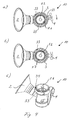
- Fig. 4 shows the manually operated breast pump 10 depicted in Figure 1 with the bayonet connection between the cover 3 and the body 15, wherein Figure 4a ) shows in top view the cover during rotation, Figure 4b ) shows in top view the cover being firmly fastened, and Figure 4c ) shows Figure 4b ) in perspective view from above.
- the manually operated breast pump 10 has only been chosen for exemplarily reasons.
- the teachings of Figure 4 apply equally well to the electrically drivable breast pump 30 depicted in Figure 2 .
- the upper side of the cover 3 (seen from the container stand 8 as lowest point) has been removed (which is indicated by reference sign 34), so that the membrane 5.1, 5.2 and the bayonet connection can be seen.
- the cover 3 comprises for example three pins (not shown) and the body 15 comprises tree corresponding slots (not shown).
- the user has to align the pins with the slots and rotate either the cover 3, or the body 15 or both of them in opposite directions in order to guide the pins into perpendicular slots which prevent the pins from being removed.
- the positions of the pins and slots define the possible positions of the lever 4 (or the tubing 31, respectively). In the example of Figures 4b) and 4c ) the lever is firmly fastened opposite the breast shield top by the bayonet connection.
- the cover 3 For clamping the rim 21 of the pot-shaped membrane 5.1 (or the rim 32 of the flexible bellow 12, respectively) while closing the bayonet connection the cover 3 (or the adapter tube cover 11, respectively) preferably has clamping cams 33 extending inwardly to further clamp the rim 21 of the pot-shaped membrane 5.1 between the cover 3 and the body 15. While closing the bayonet connection the clamping cams 33 are themselves squeezed against the inside of the cover 3 (as shown in Figure 4b )).
Landscapes
- Health & Medical Sciences (AREA)
- Heart & Thoracic Surgery (AREA)
- Biomedical Technology (AREA)
- Vascular Medicine (AREA)
- Engineering & Computer Science (AREA)
- Anesthesiology (AREA)
- Hematology (AREA)
- Life Sciences & Earth Sciences (AREA)
- Animal Behavior & Ethology (AREA)
- General Health & Medical Sciences (AREA)
- Public Health (AREA)
- Veterinary Medicine (AREA)
- Pediatric Medicine (AREA)
- External Artificial Organs (AREA)
Priority Applications (1)
| Application Number | Priority Date | Filing Date | Title |
|---|---|---|---|
| EP08019733A EP2186532A1 (de) | 2008-11-12 | 2008-11-12 | Brustpumpe |
Applications Claiming Priority (1)
| Application Number | Priority Date | Filing Date | Title |
|---|---|---|---|
| EP08019733A EP2186532A1 (de) | 2008-11-12 | 2008-11-12 | Brustpumpe |
Publications (1)
| Publication Number | Publication Date |
|---|---|
| EP2186532A1 true EP2186532A1 (de) | 2010-05-19 |
Family
ID=40547818
Family Applications (1)
| Application Number | Title | Priority Date | Filing Date |
|---|---|---|---|
| EP08019733A Withdrawn EP2186532A1 (de) | 2008-11-12 | 2008-11-12 | Brustpumpe |
Country Status (1)
| Country | Link |
|---|---|
| EP (1) | EP2186532A1 (de) |
Cited By (6)
| Publication number | Priority date | Publication date | Assignee | Title |
|---|---|---|---|---|
| EP2745858A1 (de) * | 2012-12-21 | 2014-06-25 | Wen Ching Lee | Heimpflegesaugvorrichtung |
| RU186126U1 (ru) * | 2018-09-11 | 2019-01-09 | Владимир Иванович Ильин | Выносная головка для молокоотсоса-стимулятора |
| JP2019010350A (ja) * | 2017-06-30 | 2019-01-24 | ピジョン株式会社 | 手動搾乳器 |
| JP2019198428A (ja) * | 2018-05-15 | 2019-11-21 | ピジョン株式会社 | 手動搾乳器 |
| CN112773410A (zh) * | 2021-01-25 | 2021-05-11 | 中国医学科学院肿瘤医院 | 一种乳溢取材器 |
| WO2026001217A1 (zh) * | 2024-06-26 | 2026-01-02 | 深圳市路特佳成供应链管理有限公司 | 吸奶器及其隔膜 |
Citations (3)
| Publication number | Priority date | Publication date | Assignee | Title |
|---|---|---|---|---|
| EP0733376A2 (de) | 1995-03-24 | 1996-09-25 | Cannon Rubber Limited | Membrane-Brustpumpe |
| US20030204164A1 (en) * | 2002-04-30 | 2003-10-30 | Britto James J. | Pumping breast milk |
| US20050154348A1 (en) * | 2004-01-08 | 2005-07-14 | Daniel Lantz | Breast pump |
-
2008
- 2008-11-12 EP EP08019733A patent/EP2186532A1/de not_active Withdrawn
Patent Citations (3)
| Publication number | Priority date | Publication date | Assignee | Title |
|---|---|---|---|---|
| EP0733376A2 (de) | 1995-03-24 | 1996-09-25 | Cannon Rubber Limited | Membrane-Brustpumpe |
| US20030204164A1 (en) * | 2002-04-30 | 2003-10-30 | Britto James J. | Pumping breast milk |
| US20050154348A1 (en) * | 2004-01-08 | 2005-07-14 | Daniel Lantz | Breast pump |
Cited By (14)
| Publication number | Priority date | Publication date | Assignee | Title |
|---|---|---|---|---|
| EP2745858A1 (de) * | 2012-12-21 | 2014-06-25 | Wen Ching Lee | Heimpflegesaugvorrichtung |
| CN110785190A (zh) * | 2017-06-30 | 2020-02-11 | 贝亲株式会社 | 手动挤奶器 |
| EP3646902A4 (de) * | 2017-06-30 | 2021-03-24 | Pigeon Corporation | Handbetätigte brustpumpe |
| JP2019010350A (ja) * | 2017-06-30 | 2019-01-24 | ピジョン株式会社 | 手動搾乳器 |
| CN112105397A (zh) * | 2018-05-15 | 2020-12-18 | 贝亲株式会社 | 手动吸奶器 |
| WO2019221057A1 (ja) * | 2018-05-15 | 2019-11-21 | ピジョン株式会社 | 手動搾乳器 |
| JP2019198428A (ja) * | 2018-05-15 | 2019-11-21 | ピジョン株式会社 | 手動搾乳器 |
| EP3795188A4 (de) * | 2018-05-15 | 2022-01-26 | Pigeon Corporation | Handbetätigte brustpumpe |
| CN112105397B (zh) * | 2018-05-15 | 2024-05-10 | 贝亲株式会社 | 手动吸奶器 |
| US12133942B2 (en) | 2018-05-15 | 2024-11-05 | Pigeon Corporation | Manual breast pump |
| RU186126U1 (ru) * | 2018-09-11 | 2019-01-09 | Владимир Иванович Ильин | Выносная головка для молокоотсоса-стимулятора |
| CN112773410A (zh) * | 2021-01-25 | 2021-05-11 | 中国医学科学院肿瘤医院 | 一种乳溢取材器 |
| CN112773410B (zh) * | 2021-01-25 | 2025-04-18 | 中国医学科学院肿瘤医院 | 一种乳溢取材器 |
| WO2026001217A1 (zh) * | 2024-06-26 | 2026-01-02 | 深圳市路特佳成供应链管理有限公司 | 吸奶器及其隔膜 |
Similar Documents
| Publication | Publication Date | Title |
|---|---|---|
| US20260115366A1 (en) | Breast pump | |
| CN101951972B (zh) | 挤奶装置及相关的泵装置 | |
| US8702646B2 (en) | Submersible valve for a breast milk collection device with self contained reservoir | |
| CN104936630B (zh) | 具有介质分隔装置的吸乳护罩单元 | |
| CN104955498B (zh) | 吸乳护罩单元 | |
| KR101622768B1 (ko) | 착유기 | |
| US6652484B1 (en) | Foot-powered breastmilk pump with removable piston pump | |
| EP2603252B1 (de) | Beutelbefestigungsvorrichtung für eine milchpumpe | |
| TWI597077B (zh) | 用於汲乳之泵元件 | |
| RU2337717C1 (ru) | Молокоотсосное устройство | |
| US8192396B2 (en) | Connector device | |
| EP1416979A1 (de) | Brustpumpe | |
| CN103687634A (zh) | 吸乳罩单元 | |
| JP7034614B2 (ja) | 逆流防止弁 | |
| JP2010510007A (ja) | 手動式搾乳器 | |
| US11191884B2 (en) | System for drainage of fluids or wound secretion | |
| AU2014336414B2 (en) | A breast pump device | |
| CN100457201C (zh) | 连接器装置 | |
| CN112105397B (zh) | 手动吸奶器 | |
| WO2026066612A1 (zh) | 吸奶器和储奶组件 | |
| KR20090126062A (ko) | 유축기 | |
| KR101028916B1 (ko) | 의료용 흡입장치 | |
| CN215131024U (zh) | 一种产科用负压型乳头凹陷矫正装置 | |
| KR200447947Y1 (ko) | 모유착유기용 어댑터 | |
| HK1148972A (en) | An apparatus for extracting milk from a breast and related pump unit |
Legal Events
| Date | Code | Title | Description |
|---|---|---|---|
| PUAI | Public reference made under article 153(3) epc to a published international application that has entered the european phase |
Free format text: ORIGINAL CODE: 0009012 |
|
| AK | Designated contracting states |
Kind code of ref document: A1 Designated state(s): AT BE BG CH CY CZ DE DK EE ES FI FR GB GR HR HU IE IS IT LI LT LU LV MC MT NL NO PL PT RO SE SI SK TR |
|
| AX | Request for extension of the european patent |
Extension state: AL BA MK RS |
|
| AKY | No designation fees paid | ||
| REG | Reference to a national code |
Ref country code: DE Ref legal event code: 8566 |
|
| STAA | Information on the status of an ep patent application or granted ep patent |
Free format text: STATUS: THE APPLICATION IS DEEMED TO BE WITHDRAWN |
|
| 18D | Application deemed to be withdrawn |
Effective date: 20101120 |