EP2186558B1 - Mischmaschine zur Homogenisierung eines Flüssiggemischs aus Bitumen und Festgranulaten - Google Patents
Mischmaschine zur Homogenisierung eines Flüssiggemischs aus Bitumen und Festgranulaten Download PDFInfo
- Publication number
- EP2186558B1 EP2186558B1 EP09176010.8A EP09176010A EP2186558B1 EP 2186558 B1 EP2186558 B1 EP 2186558B1 EP 09176010 A EP09176010 A EP 09176010A EP 2186558 B1 EP2186558 B1 EP 2186558B1
- Authority
- EP
- European Patent Office
- Prior art keywords
- container
- vertical axis
- solid granules
- mix
- operable
- Prior art date
- Legal status (The legal status is an assumption and is not a legal conclusion. Google has not performed a legal analysis and makes no representation as to the accuracy of the status listed.)
- Active
Links
Images


Classifications
-
- B—PERFORMING OPERATIONS; TRANSPORTING
- B01—PHYSICAL OR CHEMICAL PROCESSES OR APPARATUS IN GENERAL
- B01F—MIXING, e.g. DISSOLVING, EMULSIFYING OR DISPERSING
- B01F27/00—Mixers with rotary stirring devices in fixed receptacles; Kneaders
- B01F27/05—Stirrers
- B01F27/09—Stirrers characterised by the mounting of the stirrers with respect to the receptacle
- B01F27/091—Stirrers characterised by the mounting of the stirrers with respect to the receptacle with elements co-operating with receptacle wall or bottom, e.g. for scraping the receptacle wall
-
- B—PERFORMING OPERATIONS; TRANSPORTING
- B01—PHYSICAL OR CHEMICAL PROCESSES OR APPARATUS IN GENERAL
- B01F—MIXING, e.g. DISSOLVING, EMULSIFYING OR DISPERSING
- B01F27/00—Mixers with rotary stirring devices in fixed receptacles; Kneaders
- B01F27/05—Stirrers
- B01F27/11—Stirrers characterised by the configuration of the stirrers
- B01F27/114—Helically shaped stirrers, i.e. stirrers comprising a helically shaped band or helically shaped band sections
- B01F27/1145—Helically shaped stirrers, i.e. stirrers comprising a helically shaped band or helically shaped band sections ribbon shaped with an open space between the helical ribbon flight and the rotating axis
-
- B—PERFORMING OPERATIONS; TRANSPORTING
- B01—PHYSICAL OR CHEMICAL PROCESSES OR APPARATUS IN GENERAL
- B01F—MIXING, e.g. DISSOLVING, EMULSIFYING OR DISPERSING
- B01F27/00—Mixers with rotary stirring devices in fixed receptacles; Kneaders
- B01F27/05—Stirrers
- B01F27/11—Stirrers characterised by the configuration of the stirrers
- B01F27/17—Stirrers with additional elements mounted on the stirrer, for purposes other than mixing
- B01F27/171—Stirrers with additional elements mounted on the stirrer, for purposes other than mixing for disintegrating, e.g. for milling
-
- B—PERFORMING OPERATIONS; TRANSPORTING
- B01—PHYSICAL OR CHEMICAL PROCESSES OR APPARATUS IN GENERAL
- B01F—MIXING, e.g. DISSOLVING, EMULSIFYING OR DISPERSING
- B01F27/00—Mixers with rotary stirring devices in fixed receptacles; Kneaders
- B01F27/80—Mixers with rotary stirring devices in fixed receptacles; Kneaders with stirrers rotating about a substantially vertical axis
- B01F27/92—Mixers with rotary stirring devices in fixed receptacles; Kneaders with stirrers rotating about a substantially vertical axis with helices or screws
- B01F27/921—Mixers with rotary stirring devices in fixed receptacles; Kneaders with stirrers rotating about a substantially vertical axis with helices or screws with helices centrally mounted in the receptacle
- B01F27/9213—Mixers with rotary stirring devices in fixed receptacles; Kneaders with stirrers rotating about a substantially vertical axis with helices or screws with helices centrally mounted in the receptacle the helices having a diameter only slightly less than the diameter of the receptacle
-
- B—PERFORMING OPERATIONS; TRANSPORTING
- B01—PHYSICAL OR CHEMICAL PROCESSES OR APPARATUS IN GENERAL
- B01F—MIXING, e.g. DISSOLVING, EMULSIFYING OR DISPERSING
- B01F33/00—Other mixers; Mixing plants; Combinations of mixers
- B01F33/80—Mixing plants; Combinations of mixers
- B01F33/83—Mixing plants specially adapted for mixing in combination with disintegrating operations
- B01F33/8305—Devices with one shaft, provided with mixing and milling tools, e.g. using balls or rollers as working tools; Devices with two or more tools rotating about the same axis
-
- B—PERFORMING OPERATIONS; TRANSPORTING
- B01—PHYSICAL OR CHEMICAL PROCESSES OR APPARATUS IN GENERAL
- B01F—MIXING, e.g. DISSOLVING, EMULSIFYING OR DISPERSING
- B01F35/00—Accessories for mixers; Auxiliary operations or auxiliary devices; Parts or details of general application
- B01F35/90—Heating or cooling systems
- B01F35/92—Heating or cooling systems for heating the outside of the receptacle, e.g. heated jackets or burners
-
- B—PERFORMING OPERATIONS; TRANSPORTING
- B02—CRUSHING, PULVERISING, OR DISINTEGRATING; PREPARATORY TREATMENT OF GRAIN FOR MILLING
- B02C—CRUSHING, PULVERISING, OR DISINTEGRATING IN GENERAL; MILLING GRAIN
- B02C15/00—Disintegrating by milling members in the form of rollers or balls co-operating with rings or discs
- B02C15/08—Mills with balls or rollers centrifugally forced against the inner surface of a ring, the balls or rollers of which are driven by a centrally arranged member
-
- B—PERFORMING OPERATIONS; TRANSPORTING
- B01—PHYSICAL OR CHEMICAL PROCESSES OR APPARATUS IN GENERAL
- B01F—MIXING, e.g. DISSOLVING, EMULSIFYING OR DISPERSING
- B01F27/00—Mixers with rotary stirring devices in fixed receptacles; Kneaders
- B01F27/05—Stirrers
- B01F27/11—Stirrers characterised by the configuration of the stirrers
- B01F27/116—Stirrers shaped as cylinders, balls or rollers
Definitions
- the present invention relates to a mixing machine for homogenising a liquid mixture containing bitumen and solid granules.
- the present invention relates to a vertical axis mixing machine structured to mix a liquid mixture containing bitumen with a powder filler and solid granules made of polymeric material and/or resin-based and/or plastic material-based and/or rubber material and/or similar materials, and having the function of crushing the solid granules so as to obtain a homogenous liquid bituminous mix in order to obtain a homogenous bituminous liquid mix; to which the following description will explicitly refer without therefore loosing in generality.
- Mixing machines for bitumen comprising a cylindrical container for containing liquid bitumen, filler and solid granules to be mixed, which is developed along a vertical longitudinal axis and typically has a side air space and a bottom air space within which a serpentine is arranged, which is adapted to circulate high-temperature diathermic oil for heating the side wall and the bottom wall of the container.
- mixing machines comprise a central auger, which is arranged within the container in a position which is coaxial to the longitudinal axis and is coupled thereto in order to freely rotate about the longitudinal axis itself; and a drive shaft which is at least partially arranged within the container in a position which is coaxial to the longitudinal axis, and is actuated by an electric motor, placed outside the container itself, in order to rotate the auger about the longitudinal axis so as to determine the mixing of the liquid bitumen with the solid granules so as to obtain a liquid bituminous mix.
- the above-described auger is structured so that the distance between its crest and the vertical longitudinal rotation axis is less than the inner diameter of the container.
- the fluid mass present in the middle of the container is pushed downwards by the auger while being heated up by receiving heat from the bottom and side walls.
- the heating caused on fluid mass and solid granules determines, on one hand, a dissolution of the granules and, on the other hand, generates a convective motion which pushes the mass upwards thus determining, along with the forced motion generated by the auger, the bituminous material and dissolved granules mixing up.
- the dissolution of the solid granules may be obtained only by generating/transmitting high amounts of heat on/from the surfaces of the container, the latter being a particularly disadvantageous condition because a great amount of energy is employed for heating the diathermic oil and thus it negatively affects the total production costs of the bituminous mix.
- the above-described mixing machine is not very efficient when mixing solid granules characterized by a particularly high specific weight. Indeed, in this case, due to their weight the solid granules tend to deposit on the bottom wall of the container, not mixing homogenously with the remaining bituminous mix.
- the above-described mixing machine is not very efficient whenever solid granules characterized by a series of inner impurities having a high toughness need to be mixed. Indeed, in this case, the complete dissolution of the granule and impurities may be obtained only by considerably increasing the thermal energy and extending homogenisation times, i.e. the working times of the auger. Unfortunately, both these conditions determine prohibitive energy costs. In addition, whenever the aforesaid complete dissolution condition is not achieved, solid impurities are deposited inside the bituminous mix which causes a weakening and a thus a deterioration of the inner structure thereof.
- JP62057636A discloses an apparatus for high viscosity liquid wherein a raw material is fed through a feed port 6 into the reaction vessel 1 and is stirred and mixed by a ribbon screw 12 and plate vanes 19 via the driving shaft 7 which is driven by a motor 9.
- US5683178 relates to an agitator blades formed by connecting a plurality of frame members are provided in a cylindrical or conical container to realize the agitator blade structure without rotary shaft.
- GB628891 relates to a mixing machine of the rotary mill type and discloses a mixing machine according to the preamble of claim 1.
- JP1022332 discloses an agitating crusher wherein The material, such as ground fresh, is agitated and crushed by the spiral agitating and crushing member 10, and pushed upward along the peripheral side wall surface 9, and sent downward along the central axis after reached to the upper surface.
- a mixing machine for homogenising liquid bituminous material containing solid granules as set forth in claim 1 and preferably, but not necessarily, in any one of the claims either directly or indirectly depending from claim 1.
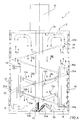
- number 1 indicates as a whole a mixing machine, which is structured for homogenising a series of components such as in particular a liquid mixture containing bitumen, a powder filler and solid granules with one another, in order to produce a bituminous mix adapted to make insulating films, applicable in the field of constructions for serving protective and/or insulating functions.
- machine 1 is further capable of mechanically crushing the solid granules so as to pulverize them and conveniently adapt them for homogenisation with the remaining components included in the bituminous mix.
- machine 1 is adapted to homogenise a mixture containing bitumen with solid granules of polymeric type preferably, but not necessarily, containing resin and/or plastic materials and/or rubber material and/or any other similar material.
- mixing machine 1 essentially comprises a container 2 which is developed along a vertical axis A and is structured so as to contain the above-described components of the bituminous mix, and a mixing assembly 3, which is mounted in an axially rotational manner within the container 2 to rotate about the axis A, and is structured for mechanically crushing solid granules against the inner side surface 2a of the container 2 so as to crumble and pulverize them, and to displace at least one portion of the mass of bituminous mix present at the surface 2a of the container 2, from the bottom surface 2b of the container 2 to the upper surface 2c opposite thereto, so as to mix the bituminous mix.
- the collection container 2 is defined by a metal container, e.g. made of steel or any other similar metal, is cylindrical in shape and integrates a heating circuit 4 within a side wall 2d thereof serving the function of transmitting heat to the inner surface 2a of the container 2 so as to rise the temperature of the bituminous mix contained therein.
- a metal container e.g. made of steel or any other similar metal
- the heating circuit 4 is of known type and therefore it will not be described in further detail except for specifying that it comprises a series of heating pipes 4a within which a heated fluid circulates, e.g. diathermic oil, adapted to yield a given amount of heat to the inner surface 2a of the side wall 2d of container 2 so as to keep the homogenised bituminous mix at a predetermined temperature.
- a heated fluid e.g. diathermic oil
- an unloading opening 5 connected to an unloading pipe (not shown), through which the homogenised bituminous mix is conveyed outwards container 2; an opening 6 connected to an outer pipe (not shown), adapted to load the filler into container 2; an opening 7 connected to an outer pipe (not shown), adapted to load the liquid mixture containing bitumen into container 2; and finally a loading opening 9 or mouth, through which the solid granules are loaded into container 2.
- the mixing assembly 3 is rotated by a central drive shaft 9, which is partially arranged within the container 2 in a position coaxial to the axis A and is connected to the outlet shaft by a driving unit 10, e.g. an electric motor, preferably but not necessarily arranged outside the container 2.
- a driving unit 10 e.g. an electric motor, preferably but not necessarily arranged outside the container 2.
- the mixing assembly 3 further comprises a central hub 11 stably fitted onto the drive shaft 9, one or more crushing device 12 which are connected to the central hub 11 by mechanical leverages 13 and are structured to crush the solid granules against the cylindrical surface 2a of the container 2 so as to crumble/pulverize them, and a scraping member 14 which is connected to the central hub 11 through a series of radial support arms 15, and serves the function of both scraping the bituminous mix, and in particular the crumbled solid granules adhering onto the inner surface 2a of the container 2, and pushing the bituminous mix present close to the surface 2a towards the upper surface 2c of the container 2.
- the mixing assembly 3 comprises a plurality of crushing devices 12, which are arranged within the container 2 being angularly spaced from one another about the axis A, and each comprising a pressure roller 16, which is arranged in abutment with the outer cylindrical surface thereof on the surface 2a of the container 2 and is mounted in an axially rotational manner on the free end of the corresponding mechanical leverage 13 so as to be able to rotate in contact with the surface 2a itself, about a corresponding axis B parallel to axis A, so as to crumble the solid granules against the surface 2a itself during its rotation.
- each pressure roller 16 is preferably but not necessarily made of metal material, and has a pair of pins 16a on its ends, which are hinged by interposing corresponding bearings on the free ends of a substantially C-shaped support bar 18 stably connected to the end of the mechanical leverage 13.
- the mechanical leverage 13 is structured so as to have a pair of radial support arms 13a vertically spaced from each other, which have the respective axial ends hinged onto the support bar 18 and on the central hub 11, respectively, so as to be arranged to be parallel and coplanar to each other and to define an articulated quadrilateral which allows the support bar 18 to move on a radial plane passing through the axis A, to and from the inner surface 2a of container 2.
- the radial support arms 13a are arranged so as to be significantly inclined upwards from the central hub 11 and outwards, so that the pressure roller 16 is kept resting with the outer cylindrical surface thereof on the surface 2a under the bias of its own weight.
- the mechanical leverage 13 may further comprise a pushing device (not shown) which is adapted to be interposed between the central hub 11 and the support bar 18 and is adapted to exert a radial force on the support bar 18, capable of keeping the pressure roller 16 constantly abutting on the inner surface 2a of the container 2 so as to crush the solid granules against the surface 2a itself.
- a pushing device (not shown) which is adapted to be interposed between the central hub 11 and the support bar 18 and is adapted to exert a radial force on the support bar 18, capable of keeping the pressure roller 16 constantly abutting on the inner surface 2a of the container 2 so as to crush the solid granules against the surface 2a itself.
- the pushing device may comprise at least one spring interposed between the support bar 18 and the central hub 11. It is worth specifying that the spring of the pushing device exerts a predetermined elastic force on the bar 18 which may be changed by means of an adjusting member (not shown) provided in the pushing device. It is apparent that the adjustment of the elastic constant of the spring made by means of the adjusting member advantageously allows to appropriately change the compression exerted by the pressure roller 16 on solid granules and bituminous material according to the type of solid granules used in the bituminous mix.
- the scraping member 14 comprises a helicoidal blade 20 preferably but not necessarily consisting of a metal strap, which extends into the container 2 in a position coaxial to the axis A according to a helicoidal curve so as to have the outer peripheral edge 20a thereof in contact with the inner surface 2a so as to be able, in use, to scrape the pulverized granules and/or bituminous material and/or filler adhering onto the inner surface 2a due to the crushing/pressing operation performed by the pressure rollers 16.
- a helicoidal blade 20 preferably but not necessarily consisting of a metal strap, which extends into the container 2 in a position coaxial to the axis A according to a helicoidal curve so as to have the outer peripheral edge 20a thereof in contact with the inner surface 2a so as to be able, in use, to scrape the pulverized granules and/or bituminous material and/or filler adhering onto the inner surface 2a due to the crushing/
- the helicoidal blade 20 is shaped so as to have the inner peripheral edge 20b thereof spaced from axis A so as to delimit therewith, during the rotation, a cylindrical inner volume of non-interference between the helicoidal blade 20 and the bituminous mix contained in container 2.
- the helicoidal blade 20 is developed along axis A so as to substantially cover the whole height H of the container 2, vertically measured along axis A, and has a width D1 which is smaller than the radius R of container 2.
- the helicoidal blade 20 comprises a number of straps or flat segments 21, which are arranged one after the other according to a helicoidal curve, are stably joined to one another at their corresponding ends and are intercalated between the pressure rollers 16.
- the bottom surface 2b of container 2 is flat and coplanar to a plane orthogonal to axis A, while the scraping member 14 comprises a scraper blade 23, which is stably connected with one end thereof onto the lower end of the central hub 11 and is arranged resting on the bottom surface 2b of container 2 so as to be able to scrape the bituminous mix and/or the components deposited on the surface 2b itself.
- the scraper blade 23 orthogonally extends to axis A and is shaped so as to have a scraping portion 23a, which is defined by a substantially rectangular, preferably but not necessarily metal plate, arranged to be inclined by a predetermined angle ⁇ with respect to the laying plane of the bottom surface 2b of container 2, and is adapted to scrape the bottom surface 2b by the its lower edge, during the rotation of the central hub 11.
- the scraper blade 23 extends orthogonally to axis A and is shaped so as to have a mixing portion 23b, which is defined by a substantially rectangular, preferably but not necessarily metal plate, arranged to be spaced and perpendicular from/to the laying plane of the bottom surface 2b of container 2, and is adapted to mix the scraped bituminous mix with the remaining bituminous mix, during the rotation of the central hub 11.
- bituminous mix i.e. bituminous liquid mixture, filler and solid granules
- the driving unit 10 rotates the mixing assembly 3 about the axis A, while the heating circuit 4 generates the heat which heats the inner surface 2a of container 2 so as to lead the components to a determined melting/dissolving temperature.
- the components of the bituminous mix are lifted upwards, i.e. towards the surface 2c, by the rotation of the helicoidal blade 20.
- the rotation of the helicoidal blade 20 further subjects the components of the mix to a centrifugal force which tends to push them towards the inner surface 2a of container 2.
- the solid granules having a higher specific weight than the remaining material conveniently tend to be accumulated on surfaces 2a.
- the rotation of pressure rollers 16 on surface 2a causes the crushing of the solid granules accumulated at the surface 2a itself, and at the same time the rotation of the helicoidal blade 20 determines the scraping of the crushed solid granules adhering onto surface 2a. Thereby, the crushed solid granules are thus detached from the surface 2a and gradually pushed upwards by the helicoidal blade 20.
- the scraping blade 23 is also rotated, which conveniently scrapes the bottom surface 2b of container 2, thus canceling all possibilities of settling the bituminous mix or components thereof on the surface 2b.
- the rotation of the helicoidal blade 20 clearly also determines a convenient mixing of the different components, in addition to the action of scraping the inner surface 2a, the action of lifting the components upwards, and the action of pushing the granules outwards.
- the motion impressed to the bituminous mix within the container has an ascending component deriving from the action of the helicoidal blade 20 and a descending component associated with the convective motion of the mix itself.
- the helicoidal blade 20 moves the bituminous mix from the bottom surface 2b, along a vertical upward path Pu, towards the upper surface 2c.
- the bituminous mix has reached the upper surface 2c, by virtue of a convective motion, it follows a downward path Pd which crosses the central non-intercepting volume of the mix towards the bottom surface 2b.
- the convective downward motion of the mix is generated by the temperature differential of the mix present in the container, which clearly has an appreciably lower temperature in the central part than the mix at the surface 2a.
- the above-described mixing machine 1 has several advantages.
- the presence of the pressure rollers allows to perform a homogenous mechanical crushing of the solid granules regardless of the toughness thereof, thereby determining both a high homogenisation of the bituminous mix and thus an excellent quality thereof, and a reduction of the thermal energy required for dissolving the components.
- the presence of the helicoidal blade increases the degree of homogenisation of the components, in addition to keeping the inner surface of the container constantly clean, with obvious advantages in terms of reduction of maintenance and cleaning operations of the container.
- the scraping action performed by the helicoidal blade is advantageous even from the point of view of energy consumption because it prevents the formation of a surface layer of material on the inner surface. Indeed, such a layer would act as a thermal insulation, thus reducing the conduction heat exchange between the inner surface and the mix, thus determining a major reduction of the machine efficiency.
- the use of the scraping blade also allows to advantageously shape the container with a flat bottom surface instead of the tapered surface present in known mixing machines, thus allowing any sizing of the container in terms of diameter and height, and obtaining a volume however having the standard capacity required by the market.
- the container may be dimensioned so as to have an inner diameter of about 2000 mm and a height of 3500 mm, and thus a capacity of about 10 cubic meters, indeed corresponding to the standard capacity required by the market. Laboratory tests demonstrated that a better thermal efficiency and a more effective mixing are determined by reducing the aforesaid dimensions of the container and increasing its height/diameter ratio.
Landscapes
- Chemical & Material Sciences (AREA)
- Chemical Kinetics & Catalysis (AREA)
- Engineering & Computer Science (AREA)
- Food Science & Technology (AREA)
- Mixers Of The Rotary Stirring Type (AREA)
- Compositions Of Macromolecular Compounds (AREA)
- Working-Up Tar And Pitch (AREA)
Claims (5)
- Bitumenmischvorrichtung (1), betreibbar zum Mischen einer flüssigen Mischung, die Bitumen mit festen Körnern enthält, zum Gewinnen einer homogenisierten flüssigen Bitumenmischung, wobei die Vorrichtung enthält:einen zylindrischen Behälter (2), der koaxial zu einer vertikalen Achse (A) angeordnet ist und betreibbar ist zum Enthalten der flüssigen Mischung, die Bitumen und die festen Körner enthält,ein Heizmittel (4), das betreibbar ist zum Heizen der Innenoberfläche (2a) der Seitenwand (2d) des zylindrischen Behälters (2),eine Mischeinrichtung (3), die axial drehbar in dem Behälter (2) angeordnet ist und betreibbar ist zum Drehen um die vertikale Achse (A), undeine Antriebseinheit (10), die betreibbar ist zum Drehen der Mischeinrichtung (3) um die vertikale Achse (A),wobei die Mischeinrichtung (3) ein Quetschmittel (12) enthält, das so aufgebaut ist, dass es die festen Körner mechanisch gegen die Innenoberfläche (2a) des Behälters (2) quetscht,das Quetschmittel (12) zumindest eine Druckwalze (16) enthält, die mit ihrer äußeren Zylinderoberfläche in Anschlag an der Innenoberfläche (2a) des Behälters (2) angeordnet ist und daran angepasst ist, sich während der Drehung der Mischeinrichtung (3) um eine Achse (B) zu drehen, die parallel zu der vertikalen Achse (A) angeordnet ist, zum Quetschen der festen Körner gegen die Innenoberfläche (2a) des Behälters (2),die Mischeinrichtung (3) ein Abstreifmittel (14) enthält
unddie Bitumenmischvorrichtung dadurch gekennzeichnet ist, dassdas Abstreifmittel (14) eine helixförmige Klinge (20) enthält, die sich koaxial zu der Achse (A) in dem Behälter (2) erstreckt und deren äußere Umfangskante (20a) in Kontakt mit der Innenoberfläche (2a) des Behälters (2) ist, zum Abstreifen des Materials, das an der Innenoberfläche (2a) haftet,die helixförmig Klinge (20) betreibbar ist zum Drehen um die vertikal Achse (A) zum Bewegen zumindest eines Teils der Masse der bituminösen Mischung, die an der Innenoberfläche (2a) des Behälters (2) vorhanden ist, von der Grundfläche (2b) des Behälters (2) zu der dieser gegenüberliegenden Deckfläche (2c) zum Mischen der bituminösen Mischung,die helixförmig Klinge (20) weiter eine Anzahl flacher Segmente (21) enthält, die hintereinander entsprechend einer Helixkurve angeordnet sind und an ihren Enden stabil miteinander verbunden sind, unddie flachen Segmente (21) zwischen den Druckrollen (16) eingefügt sind. - Vorrichtung gemäß Anspruch 1, bei der die helixförmige Klinge (20) so profiliert ist, dass ihre innere Umfangskante (20b) von der vertikalen Achse (A) beabstandet ist.
- Vorrichtung gemäß Anspruch 1 oder 2, bei der die helixförmig Klinge (20) sich so entlang der vertikalen Achse (A) herausbildet, dass sie die gesamte Höhe (H) des Behälters (2) einnimmt und eine Breite (D1) hat, die kleiner ist als der Radius (R) des Behälters (2).
- Vorrichtung gemäß einem der vorigen Ansprüche,
die eine Mittelnabe (11) enthält, die koaxial zu der vertikalen Achse (A) in dem Behälter (2) angeordnet ist,
wobei die Enden der Druckwalze (16) an einen Haltebalken (18) aufgehängt sind, der mit der Mittelnabe (11) über eine mechanische Hebelanordnung (13) verbunden ist, die so aufgebaut ist, dass sie es ermöglicht, den Haltebalken (18) auf einer radialen Ebene, die durch die vertikale Achse (A) hindurchgeht, von der Innenoberfläche (2a) des Behälters (2) weg und zu ihr hin zu verschieben. - Vorrichtung gemäß einem der vorigen Ansprüche, bei der
die Grundfläche (2b) des Behälters (2) eben und koplanar zu einer Ebene ist, die senkrecht zu der vertikalen Achse (A) verläuft, und
das Abstreifmittel (14) eine Abstreifklinge (23) enthält, die stabil mit der Mittelnabe (11) verbunden ist und so angeordnet ist, dass sie auf der Grundfläche (2b) des Behälters (2) ruht, zum Durchführen eines Abstreifens der bituminösen Mischung und/oder der Komponenten, die sich auf der Grundfläche (2b) abgelagert haben.
Applications Claiming Priority (1)
| Application Number | Priority Date | Filing Date | Title |
|---|---|---|---|
| ITTO2008A000839A IT1394446B1 (it) | 2008-11-13 | 2008-11-13 | Macchina miscelatrice per omogeneizzare una miscela liquida a base di bitume con granuli solidi |
Publications (2)
| Publication Number | Publication Date |
|---|---|
| EP2186558A1 EP2186558A1 (de) | 2010-05-19 |
| EP2186558B1 true EP2186558B1 (de) | 2014-01-01 |
Family
ID=41112825
Family Applications (1)
| Application Number | Title | Priority Date | Filing Date |
|---|---|---|---|
| EP09176010.8A Active EP2186558B1 (de) | 2008-11-13 | 2009-11-13 | Mischmaschine zur Homogenisierung eines Flüssiggemischs aus Bitumen und Festgranulaten |
Country Status (3)
| Country | Link |
|---|---|
| US (1) | US8505842B2 (de) |
| EP (1) | EP2186558B1 (de) |
| IT (1) | IT1394446B1 (de) |
Families Citing this family (32)
| Publication number | Priority date | Publication date | Assignee | Title |
|---|---|---|---|---|
| JP5572899B2 (ja) * | 2010-03-26 | 2014-08-20 | 株式会社奈良機械製作所 | 粉体の造粒方法及び造粒装置 |
| IT1400451B1 (it) * | 2010-06-08 | 2013-05-31 | Euroline Srl | Macchina miscelatrice per produrre conglomerati liquidi bituminosi. |
| US9381550B2 (en) * | 2013-05-06 | 2016-07-05 | Spokane Industires | Self-cleaning tank |
| US10058872B2 (en) * | 2014-07-03 | 2018-08-28 | STT Enviro Corp. | Vertical ball mill with internal materials flow conduit |
| US9764295B2 (en) * | 2015-02-10 | 2017-09-19 | Cathay Coating Manufacture Co., Ltd. | Mixing and grinding mechanism and mixer grinder using the same |
| CA2923039C (en) | 2015-03-09 | 2023-09-12 | Heritage Research Group | Void reducing asphalt membrane composition, method and apparatus for asphalt paving applications |
| CA2923021C (en) | 2015-03-10 | 2023-08-01 | Heritage Research Group | Apparatus and method for applying asphalt binder compositions including void reducing asphalt membrane compositions for paving applications |
| DE102015105804A1 (de) * | 2015-04-16 | 2016-10-20 | Netzsch-Feinmahltechnik Gmbh | Rührwerkskugelmühle |
| CN105521729A (zh) * | 2015-12-08 | 2016-04-27 | 无锡万能胶粘剂有限公司 | 一种粘合剂搅拌罐 |
| CN108848830A (zh) * | 2018-07-02 | 2018-11-23 | 合肥亚卡普机械科技有限公司 | 一种农业混合颗粒施肥机械 |
| CN111888993A (zh) * | 2019-05-05 | 2020-11-06 | 江苏察克润滑科技有限公司 | 一种应用于润滑油生产的搅拌设备 |
| CN110801886B (zh) * | 2019-10-18 | 2021-06-01 | 常州盘石水泥有限公司 | 一种水泥熟料生产装置 |
| CN110694534A (zh) * | 2019-11-18 | 2020-01-17 | 山东捷利尔肥业有限公司 | 一种提高石榴富硒功能的生物有机肥粉碎混合装置 |
| FR3109536B1 (fr) | 2020-04-22 | 2022-03-18 | Soprema | Raffineur pour le traitement de produits composites |
| US12404453B2 (en) * | 2020-08-28 | 2025-09-02 | Res Polyflow Llc | Helical stirring system for a plastic conversion vessel |
| CN112224685A (zh) * | 2020-09-23 | 2021-01-15 | 韩智源 | 一种合成pu树脂恒温储存罐 |
| CN112221597B (zh) * | 2020-09-24 | 2021-12-24 | 清远市方元新型材料有限公司 | 一种高岭土制备加工系统 |
| CN112221598B (zh) * | 2020-09-24 | 2021-03-30 | 茂名市南泉高岭土实业有限公司 | 一种高岭土制备方法 |
| CN112427110B (zh) * | 2020-11-17 | 2022-04-15 | 广西横县妙莲茶业有限公司 | 一种袋泡茶磨茶机 |
| CN112337384B (zh) * | 2021-01-11 | 2021-04-20 | 烟台雅米宠物食品有限公司 | 一种狗粮加工用的材料搅拌装置 |
| CN113083098B (zh) * | 2021-04-01 | 2023-02-03 | 枣庄学院 | 一种自动化生产线搅拌装置 |
| CN113351094A (zh) * | 2021-06-09 | 2021-09-07 | 扬州市鑫通交通器材集团有限公司 | 一种交通施工沥青废料处理设备 |
| CN113230965B (zh) * | 2021-06-16 | 2022-08-23 | 重庆天致药业股份有限公司 | 一种具有自动上料机构的制药混合机 |
| CN113863092B (zh) * | 2021-09-26 | 2022-09-20 | 北京盛广拓再生科技股份有限公司 | 冬季冷补料生产装置及其生产方法 |
| CN114950238A (zh) * | 2022-05-23 | 2022-08-30 | 郑州长城冶金设备有限公司 | 一种混合机 |
| CN115634740B (zh) * | 2022-10-26 | 2023-05-30 | 江苏培蕾基质科技发展有限公司 | 一种草莓育苗基质多样原基材按比同步粉碎设备及其使用方法 |
| CN115652732B (zh) * | 2022-12-28 | 2023-03-17 | 喜跃发国际环保新材料股份有限公司 | 一种改性沥青的加工工艺及加工系统 |
| CN116272584B (zh) * | 2023-02-14 | 2024-01-19 | 郑州聚合缘新材料科技有限公司 | 一种碱激发基纯无机功能性内墙涂料的生产系统及方法 |
| CN116510560A (zh) * | 2023-04-22 | 2023-08-01 | 常州仁久工程检测咨询有限公司 | 一种自动制取料机 |
| CN116603426B (zh) * | 2023-07-19 | 2023-10-10 | 佛山科学技术学院 | 一种环保型沥青混合料联动混合装置及混合方法 |
| CN116899473B (zh) * | 2023-09-12 | 2023-11-28 | 吉林省煜晖生物科技有限公司 | 一种药剂混合搅拌装置 |
| CN117643823B (zh) * | 2024-01-30 | 2024-04-30 | 多氟多(昆明)科技开发有限公司 | 一种方便添料的冰晶石制造用搅拌合成装置 |
Family Cites Families (16)
| Publication number | Priority date | Publication date | Assignee | Title |
|---|---|---|---|---|
| US1349235A (en) * | 1919-05-22 | 1920-08-10 | Oscar M Stout | Chocolate-developing machinery |
| GB628891A (en) * | 1947-04-29 | 1949-09-07 | Beardsley & Piper Co | Rotary crushing mills |
| NL268801A (de) * | 1960-09-05 | |||
| NL109760C (de) * | 1961-01-09 | |||
| US3156451A (en) * | 1961-02-16 | 1964-11-10 | Manley Inc | Rotatable agitator |
| DE2124642C3 (de) * | 1970-05-19 | 1974-03-07 | Japan Exlan Co. Ltd., Osaka (Japan) | Rührvorrichtung |
| DE3008933A1 (de) * | 1980-03-08 | 1981-09-17 | Eugen Peter Fa | Misch- und ruehreinrichtung fuer einen zur lagerung von fluessigkeit enthaltenden medien wie maische, weine, saefte, dickstoffe, konzentrate dienenden behaelter |
| JPS57125202A (en) * | 1981-01-28 | 1982-08-04 | Mitsui Toatsu Chem Inc | Device for continuous bulk polymerization |
| JPS6257636A (ja) * | 1985-09-06 | 1987-03-13 | Sakura Seisakusho:Kk | 高粘度液反応装置 |
| JPS6422332A (en) * | 1987-07-20 | 1989-01-25 | Yoshihito Sano | Agitating crusher |
| KR0140525B1 (ko) * | 1989-02-03 | 1998-06-01 | 미다 가쓰시게 | 고점성물질의 제조장치 및 제조방법 |
| JP2533566Y2 (ja) * | 1991-10-16 | 1997-04-23 | 正夫 金井 | 乾燥装置 |
| JP2649131B2 (ja) | 1992-11-18 | 1997-09-03 | 神鋼パンテツク株式会社 | 攪拌装置及びこれに使用するボトムリボン翼 |
| DE19640740A1 (de) * | 1996-10-02 | 1998-04-23 | Bayer Ag | Wärmeaustauschrührer |
| DE10359379B4 (de) * | 2002-12-28 | 2010-10-28 | Backhaus, Martin, Dipl.-Ing. | Schraubenbandmischer |
| ITTO20070098A1 (it) * | 2007-02-09 | 2008-08-10 | Euroline Srl | Macchina e metodo per omogeneizzare una miscela a base di bitume con dei granuli polimerici |
-
2008
- 2008-11-13 IT ITTO2008A000839A patent/IT1394446B1/it active
-
2009
- 2009-11-13 US US12/618,642 patent/US8505842B2/en active Active
- 2009-11-13 EP EP09176010.8A patent/EP2186558B1/de active Active
Also Published As
| Publication number | Publication date |
|---|---|
| US8505842B2 (en) | 2013-08-13 |
| ITTO20080839A1 (it) | 2010-05-14 |
| IT1394446B1 (it) | 2012-06-15 |
| EP2186558A1 (de) | 2010-05-19 |
| US20100127106A1 (en) | 2010-05-27 |
Similar Documents
| Publication | Publication Date | Title |
|---|---|---|
| EP2186558B1 (de) | Mischmaschine zur Homogenisierung eines Flüssiggemischs aus Bitumen und Festgranulaten | |
| EP2468407B1 (de) | Homogenisierungsmühle mit rollen | |
| EP2125181B1 (de) | Maschine und verfahren zur homogenisierung einer auf bitumen basierenden mischung mit polymergranulat | |
| CN102935350B (zh) | 一种立式强化多糖高聚物改性搅拌球磨反应器 | |
| CN216419094U (zh) | 一种沥青混合料循环加热搅拌装置 | |
| CN222093209U (zh) | 一种定量加药装置 | |
| CN213680530U (zh) | 一种沥青生产用混合均匀的配料罐 | |
| CN217346367U (zh) | 一种聚氨酯保温芯材连续发泡在线配料混料装置 | |
| CN111054236A (zh) | 一种强化预混合处理的废弃物处理装置 | |
| CN103512337B (zh) | 间接加热式干燥装置 | |
| CN119425442A (zh) | 一种碳酸钙加工用配料装置 | |
| KR101044098B1 (ko) | 고체연료 성형기 | |
| CN117303684B (zh) | 干化造粒机 | |
| BG4104U1 (bg) | Термокинетичен смесител за смесване чрез стопяване на пластмасови отпадъчни продукти | |
| CN220478678U (zh) | 一种胶料保温搅拌桶结构 | |
| EP0066392A2 (de) | Zerkleinungsverfahren | |
| CN217221303U (zh) | 一种节能型具有温度稳定功能的自动加药机 | |
| CN216367574U (zh) | 一种便于对大颗粒进行筛选的化工生产用搅拌釜 | |
| CN216025343U (zh) | 一种湿法混合制粒机 | |
| CN210875651U (zh) | 黏土和铁粉的混合搅碎机 | |
| CN221333868U (zh) | 一种氮化硼粉料混合装置 | |
| CN218358964U (zh) | 一种化工树脂加工用原料混合装置 | |
| CN221971504U (zh) | 一种改性沥青快速升温装置 | |
| CN217189295U (zh) | 一种反应釜的预混装置 | |
| CN222789172U (zh) | 一种化工安全投料装置 |
Legal Events
| Date | Code | Title | Description |
|---|---|---|---|
| PUAI | Public reference made under article 153(3) epc to a published international application that has entered the european phase |
Free format text: ORIGINAL CODE: 0009012 |
|
| AK | Designated contracting states |
Kind code of ref document: A1 Designated state(s): AT BE BG CH CY CZ DE DK EE ES FI FR GB GR HR HU IE IS IT LI LT LU LV MC MK MT NL NO PL PT RO SE SI SK SM TR |
|
| AX | Request for extension of the european patent |
Extension state: AL BA RS |
|
| 17P | Request for examination filed |
Effective date: 20101119 |
|
| 17Q | First examination report despatched |
Effective date: 20110124 |
|
| GRAP | Despatch of communication of intention to grant a patent |
Free format text: ORIGINAL CODE: EPIDOSNIGR1 |
|
| RIC1 | Information provided on ipc code assigned before grant |
Ipc: B02C 15/08 20060101ALI20130513BHEP Ipc: B01F 13/10 20060101ALI20130513BHEP Ipc: B01F 15/06 20060101ALI20130513BHEP Ipc: B01F 7/00 20060101AFI20130513BHEP Ipc: B01F 7/24 20060101ALI20130513BHEP |
|
| INTG | Intention to grant announced |
Effective date: 20130613 |
|
| GRAS | Grant fee paid |
Free format text: ORIGINAL CODE: EPIDOSNIGR3 |
|
| GRAA | (expected) grant |
Free format text: ORIGINAL CODE: 0009210 |
|
| AK | Designated contracting states |
Kind code of ref document: B1 Designated state(s): AT BE BG CH CY CZ DE DK EE ES FI FR GB GR HR HU IE IS IT LI LT LU LV MC MK MT NL NO PL PT RO SE SI SK SM TR |
|
| REG | Reference to a national code |
Ref country code: GB Ref legal event code: FG4D |
|
| REG | Reference to a national code |
Ref country code: CH Ref legal event code: EP |
|
| REG | Reference to a national code |
Ref country code: IE Ref legal event code: FG4D |
|
| REG | Reference to a national code |
Ref country code: DE Ref legal event code: R096 Ref document number: 602009021113 Country of ref document: DE Effective date: 20140213 |
|
| REG | Reference to a national code |
Ref country code: AT Ref legal event code: REF Ref document number: 647338 Country of ref document: AT Kind code of ref document: T Effective date: 20140215 |
|
| REG | Reference to a national code |
Ref country code: NL Ref legal event code: VDEP Effective date: 20140101 |
|
| REG | Reference to a national code |
Ref country code: AT Ref legal event code: MK05 Ref document number: 647338 Country of ref document: AT Kind code of ref document: T Effective date: 20140101 |
|
| REG | Reference to a national code |
Ref country code: LT Ref legal event code: MG4D |
|
| PG25 | Lapsed in a contracting state [announced via postgrant information from national office to epo] |
Ref country code: LT Free format text: LAPSE BECAUSE OF FAILURE TO SUBMIT A TRANSLATION OF THE DESCRIPTION OR TO PAY THE FEE WITHIN THE PRESCRIBED TIME-LIMIT Effective date: 20140101 Ref country code: IS Free format text: LAPSE BECAUSE OF FAILURE TO SUBMIT A TRANSLATION OF THE DESCRIPTION OR TO PAY THE FEE WITHIN THE PRESCRIBED TIME-LIMIT Effective date: 20140501 |
|
| PG25 | Lapsed in a contracting state [announced via postgrant information from national office to epo] |
Ref country code: SE Free format text: LAPSE BECAUSE OF FAILURE TO SUBMIT A TRANSLATION OF THE DESCRIPTION OR TO PAY THE FEE WITHIN THE PRESCRIBED TIME-LIMIT Effective date: 20140101 Ref country code: NL Free format text: LAPSE BECAUSE OF FAILURE TO SUBMIT A TRANSLATION OF THE DESCRIPTION OR TO PAY THE FEE WITHIN THE PRESCRIBED TIME-LIMIT Effective date: 20140101 Ref country code: CY Free format text: LAPSE BECAUSE OF FAILURE TO SUBMIT A TRANSLATION OF THE DESCRIPTION OR TO PAY THE FEE WITHIN THE PRESCRIBED TIME-LIMIT Effective date: 20140101 Ref country code: FI Free format text: LAPSE BECAUSE OF FAILURE TO SUBMIT A TRANSLATION OF THE DESCRIPTION OR TO PAY THE FEE WITHIN THE PRESCRIBED TIME-LIMIT Effective date: 20140101 Ref country code: AT Free format text: LAPSE BECAUSE OF FAILURE TO SUBMIT A TRANSLATION OF THE DESCRIPTION OR TO PAY THE FEE WITHIN THE PRESCRIBED TIME-LIMIT Effective date: 20140101 Ref country code: ES Free format text: LAPSE BECAUSE OF FAILURE TO SUBMIT A TRANSLATION OF THE DESCRIPTION OR TO PAY THE FEE WITHIN THE PRESCRIBED TIME-LIMIT Effective date: 20140101 Ref country code: PT Free format text: LAPSE BECAUSE OF FAILURE TO SUBMIT A TRANSLATION OF THE DESCRIPTION OR TO PAY THE FEE WITHIN THE PRESCRIBED TIME-LIMIT Effective date: 20140502 |
|
| PG25 | Lapsed in a contracting state [announced via postgrant information from national office to epo] |
Ref country code: LV Free format text: LAPSE BECAUSE OF FAILURE TO SUBMIT A TRANSLATION OF THE DESCRIPTION OR TO PAY THE FEE WITHIN THE PRESCRIBED TIME-LIMIT Effective date: 20140101 Ref country code: BE Free format text: LAPSE BECAUSE OF FAILURE TO SUBMIT A TRANSLATION OF THE DESCRIPTION OR TO PAY THE FEE WITHIN THE PRESCRIBED TIME-LIMIT Effective date: 20140101 Ref country code: HR Free format text: LAPSE BECAUSE OF FAILURE TO SUBMIT A TRANSLATION OF THE DESCRIPTION OR TO PAY THE FEE WITHIN THE PRESCRIBED TIME-LIMIT Effective date: 20140101 |
|
| REG | Reference to a national code |
Ref country code: DE Ref legal event code: R097 Ref document number: 602009021113 Country of ref document: DE |
|
| PG25 | Lapsed in a contracting state [announced via postgrant information from national office to epo] |
Ref country code: RO Free format text: LAPSE BECAUSE OF FAILURE TO SUBMIT A TRANSLATION OF THE DESCRIPTION OR TO PAY THE FEE WITHIN THE PRESCRIBED TIME-LIMIT Effective date: 20140101 Ref country code: DK Free format text: LAPSE BECAUSE OF FAILURE TO SUBMIT A TRANSLATION OF THE DESCRIPTION OR TO PAY THE FEE WITHIN THE PRESCRIBED TIME-LIMIT Effective date: 20140101 Ref country code: EE Free format text: LAPSE BECAUSE OF FAILURE TO SUBMIT A TRANSLATION OF THE DESCRIPTION OR TO PAY THE FEE WITHIN THE PRESCRIBED TIME-LIMIT Effective date: 20140101 Ref country code: CZ Free format text: LAPSE BECAUSE OF FAILURE TO SUBMIT A TRANSLATION OF THE DESCRIPTION OR TO PAY THE FEE WITHIN THE PRESCRIBED TIME-LIMIT Effective date: 20140101 |
|
| PLBE | No opposition filed within time limit |
Free format text: ORIGINAL CODE: 0009261 |
|
| STAA | Information on the status of an ep patent application or granted ep patent |
Free format text: STATUS: NO OPPOSITION FILED WITHIN TIME LIMIT |
|
| PG25 | Lapsed in a contracting state [announced via postgrant information from national office to epo] |
Ref country code: SK Free format text: LAPSE BECAUSE OF FAILURE TO SUBMIT A TRANSLATION OF THE DESCRIPTION OR TO PAY THE FEE WITHIN THE PRESCRIBED TIME-LIMIT Effective date: 20140101 Ref country code: PL Free format text: LAPSE BECAUSE OF FAILURE TO SUBMIT A TRANSLATION OF THE DESCRIPTION OR TO PAY THE FEE WITHIN THE PRESCRIBED TIME-LIMIT Effective date: 20140101 |
|
| 26N | No opposition filed |
Effective date: 20141002 |
|
| REG | Reference to a national code |
Ref country code: DE Ref legal event code: R097 Ref document number: 602009021113 Country of ref document: DE Effective date: 20141002 |
|
| PG25 | Lapsed in a contracting state [announced via postgrant information from national office to epo] |
Ref country code: SI Free format text: LAPSE BECAUSE OF FAILURE TO SUBMIT A TRANSLATION OF THE DESCRIPTION OR TO PAY THE FEE WITHIN THE PRESCRIBED TIME-LIMIT Effective date: 20140101 |
|
| PG25 | Lapsed in a contracting state [announced via postgrant information from national office to epo] |
Ref country code: MC Free format text: LAPSE BECAUSE OF FAILURE TO SUBMIT A TRANSLATION OF THE DESCRIPTION OR TO PAY THE FEE WITHIN THE PRESCRIBED TIME-LIMIT Effective date: 20140101 Ref country code: LU Free format text: LAPSE BECAUSE OF FAILURE TO SUBMIT A TRANSLATION OF THE DESCRIPTION OR TO PAY THE FEE WITHIN THE PRESCRIBED TIME-LIMIT Effective date: 20141113 |
|
| REG | Reference to a national code |
Ref country code: CH Ref legal event code: PL |
|
| GBPC | Gb: european patent ceased through non-payment of renewal fee |
Effective date: 20141113 |
|
| PG25 | Lapsed in a contracting state [announced via postgrant information from national office to epo] |
Ref country code: CH Free format text: LAPSE BECAUSE OF NON-PAYMENT OF DUE FEES Effective date: 20141130 Ref country code: LI Free format text: LAPSE BECAUSE OF NON-PAYMENT OF DUE FEES Effective date: 20141130 |
|
| REG | Reference to a national code |
Ref country code: IE Ref legal event code: MM4A |
|
| REG | Reference to a national code |
Ref country code: FR Ref legal event code: PLFP Year of fee payment: 7 |
|
| PG25 | Lapsed in a contracting state [announced via postgrant information from national office to epo] |
Ref country code: GB Free format text: LAPSE BECAUSE OF NON-PAYMENT OF DUE FEES Effective date: 20141113 Ref country code: IE Free format text: LAPSE BECAUSE OF NON-PAYMENT OF DUE FEES Effective date: 20141113 |
|
| PG25 | Lapsed in a contracting state [announced via postgrant information from national office to epo] |
Ref country code: SM Free format text: LAPSE BECAUSE OF FAILURE TO SUBMIT A TRANSLATION OF THE DESCRIPTION OR TO PAY THE FEE WITHIN THE PRESCRIBED TIME-LIMIT Effective date: 20140101 Ref country code: NO Free format text: LAPSE BECAUSE OF FAILURE TO SUBMIT A TRANSLATION OF THE DESCRIPTION OR TO PAY THE FEE WITHIN THE PRESCRIBED TIME-LIMIT Effective date: 20140401 |
|
| PG25 | Lapsed in a contracting state [announced via postgrant information from national office to epo] |
Ref country code: GR Free format text: LAPSE BECAUSE OF FAILURE TO SUBMIT A TRANSLATION OF THE DESCRIPTION OR TO PAY THE FEE WITHIN THE PRESCRIBED TIME-LIMIT Effective date: 20140402 Ref country code: IT Free format text: LAPSE BECAUSE OF FAILURE TO SUBMIT A TRANSLATION OF THE DESCRIPTION OR TO PAY THE FEE WITHIN THE PRESCRIBED TIME-LIMIT Effective date: 20140101 Ref country code: BG Free format text: LAPSE BECAUSE OF FAILURE TO SUBMIT A TRANSLATION OF THE DESCRIPTION OR TO PAY THE FEE WITHIN THE PRESCRIBED TIME-LIMIT Effective date: 20140101 |
|
| PG25 | Lapsed in a contracting state [announced via postgrant information from national office to epo] |
Ref country code: MT Free format text: LAPSE BECAUSE OF FAILURE TO SUBMIT A TRANSLATION OF THE DESCRIPTION OR TO PAY THE FEE WITHIN THE PRESCRIBED TIME-LIMIT Effective date: 20140101 Ref country code: TR Free format text: LAPSE BECAUSE OF FAILURE TO SUBMIT A TRANSLATION OF THE DESCRIPTION OR TO PAY THE FEE WITHIN THE PRESCRIBED TIME-LIMIT Effective date: 20140101 Ref country code: HU Free format text: LAPSE BECAUSE OF FAILURE TO SUBMIT A TRANSLATION OF THE DESCRIPTION OR TO PAY THE FEE WITHIN THE PRESCRIBED TIME-LIMIT; INVALID AB INITIO Effective date: 20091113 |
|
| REG | Reference to a national code |
Ref country code: FR Ref legal event code: PLFP Year of fee payment: 8 |
|
| REG | Reference to a national code |
Ref country code: FR Ref legal event code: PLFP Year of fee payment: 9 |
|
| PG25 | Lapsed in a contracting state [announced via postgrant information from national office to epo] |
Ref country code: MK Free format text: LAPSE BECAUSE OF FAILURE TO SUBMIT A TRANSLATION OF THE DESCRIPTION OR TO PAY THE FEE WITHIN THE PRESCRIBED TIME-LIMIT Effective date: 20140101 |
|
| REG | Reference to a national code |
Ref country code: DE Ref legal event code: R079 Ref document number: 602009021113 Country of ref document: DE Free format text: PREVIOUS MAIN CLASS: B01F0007000000 Ipc: B01F0027000000 |
|
| PGFP | Annual fee paid to national office [announced via postgrant information from national office to epo] |
Ref country code: DE Payment date: 20251126 Year of fee payment: 17 |
|
| PGFP | Annual fee paid to national office [announced via postgrant information from national office to epo] |
Ref country code: FR Payment date: 20251124 Year of fee payment: 17 |