EP2186575B1 - Dispositif de séparation d'un mélange pulvérulent dans un flux d'écoulement - Google Patents
Dispositif de séparation d'un mélange pulvérulent dans un flux d'écoulement Download PDFInfo
- Publication number
- EP2186575B1 EP2186575B1 EP07834954.5A EP07834954A EP2186575B1 EP 2186575 B1 EP2186575 B1 EP 2186575B1 EP 07834954 A EP07834954 A EP 07834954A EP 2186575 B1 EP2186575 B1 EP 2186575B1
- Authority
- EP
- European Patent Office
- Prior art keywords
- separation chamber
- fractions
- embodied
- air
- bulk material
- Prior art date
- Legal status (The legal status is an assumption and is not a legal conclusion. Google has not performed a legal analysis and makes no representation as to the accuracy of the status listed.)
- Not-in-force
Links
- 239000012530 fluid Substances 0.000 title 1
- 239000000203 mixture Substances 0.000 title 1
- 238000000926 separation method Methods 0.000 claims description 75
- 239000013590 bulk material Substances 0.000 claims description 29
- 230000009969 flowable effect Effects 0.000 claims description 10
- 230000000630 rising effect Effects 0.000 claims description 6
- 239000002245 particle Substances 0.000 description 19
- 239000000463 material Substances 0.000 description 14
- 235000013339 cereals Nutrition 0.000 description 9
- 230000001174 ascending effect Effects 0.000 description 8
- 230000015572 biosynthetic process Effects 0.000 description 5
- 240000006829 Ficus sundaica Species 0.000 description 3
- 238000004140 cleaning Methods 0.000 description 3
- 230000000694 effects Effects 0.000 description 3
- 238000004519 manufacturing process Methods 0.000 description 3
- 230000001154 acute effect Effects 0.000 description 2
- 238000009395 breeding Methods 0.000 description 2
- 230000001488 breeding effect Effects 0.000 description 2
- 230000008859 change Effects 0.000 description 2
- 230000003993 interaction Effects 0.000 description 2
- 230000009467 reduction Effects 0.000 description 2
- 239000007787 solid Substances 0.000 description 2
- 241000196324 Embryophyta Species 0.000 description 1
- 241000209504 Poaceae Species 0.000 description 1
- 230000009471 action Effects 0.000 description 1
- 238000004378 air conditioning Methods 0.000 description 1
- 150000001875 compounds Chemical class 0.000 description 1
- 238000013016 damping Methods 0.000 description 1
- 230000007812 deficiency Effects 0.000 description 1
- 238000010790 dilution Methods 0.000 description 1
- 239000012895 dilution Substances 0.000 description 1
- 238000007599 discharging Methods 0.000 description 1
- 238000006073 displacement reaction Methods 0.000 description 1
- 238000009826 distribution Methods 0.000 description 1
- 235000013312 flour Nutrition 0.000 description 1
- 235000013305 food Nutrition 0.000 description 1
- 230000005484 gravity Effects 0.000 description 1
- 239000007788 liquid Substances 0.000 description 1
- 239000002184 metal Substances 0.000 description 1
- 238000000034 method Methods 0.000 description 1
- 238000005457 optimization Methods 0.000 description 1
- 238000002360 preparation method Methods 0.000 description 1
- 230000008569 process Effects 0.000 description 1
- 238000005070 sampling Methods 0.000 description 1
- 239000000243 solution Substances 0.000 description 1
- 230000006641 stabilisation Effects 0.000 description 1
- 238000011105 stabilization Methods 0.000 description 1
- 238000003860 storage Methods 0.000 description 1
- 235000013311 vegetables Nutrition 0.000 description 1
- 238000009333 weeding Methods 0.000 description 1
Images

Classifications
-
- B—PERFORMING OPERATIONS; TRANSPORTING
- B07—SEPARATING SOLIDS FROM SOLIDS; SORTING
- B07B—SEPARATING SOLIDS FROM SOLIDS BY SIEVING, SCREENING, SIFTING OR BY USING GAS CURRENTS; SEPARATING BY OTHER DRY METHODS APPLICABLE TO BULK MATERIAL, e.g. LOOSE ARTICLES FIT TO BE HANDLED LIKE BULK MATERIAL
- B07B4/00—Separating solids from solids by subjecting their mixture to gas currents
- B07B4/02—Separating solids from solids by subjecting their mixture to gas currents while the mixtures fall
Definitions
- the invention relates to plants for the sorting of solid bulk materials by means of air streams. More particularly, the invention relates to automated equipment for cleaning grain, cereals, cereals, vegetables and grasses. It can be used in breeding stations, seed factories, farms, grain storage facilities, flour production and compound feed production.
- Each of these devices includes a hopper, a separation chamber, an airflow nozzle connected to a pressure fan, and reservoirs for finished fractions (see copyright certificate SU 1479141 , AI. B07B4 / 02, published on 15.05.1989, Pat. RU 2130816 , AI. B07B4 / 02, published on 27.05.1999, Pat. RU 2132754 , AI. B07B4 / 02, published 10.07.1999, or Pat. RU 2132755 , AI. B07B4 / 02, published on 10.07.1999).
- a common shortcoming of said facilities is the lack of ascending air flow, which flows counter to the bulk material to be separated. Thereby, the effective time of remaining the bulk material in the separation chamber is shortened, and the separation conditions are deteriorated. This leads to unfounded increases in the outer dimensions of the separation chamber and the entire device.
- a device for the air classification of disperse materials consists of a compressed air space, a feed assembly to throw the disperse materials into the compressed air space longitudinally, sump for wind sifting products, which are arranged in the lower part of the compressed air space successively from the feed assembly, a system for controllably supplying the vertically rising air streams in the compressed air space, and a suction system.
- the system for the controllable supply of the vertical air streams into the compressed air space in the form of slot nozzles is provided by a gradual damping of the speed of the disperse materials to be injected along the compressed air space formed, which are mounted across the compressed air space between the collecting containers for the air classification products.
- the device is preferably provided with an extra slot nozzle, which is rotatably arranged on the end face of the compressed air space with respect to the feed assembly of the disperse materials.
- a bulk solids separator including a bunker with a baffle, a separation chamber, a blower and air ducts.
- the separation chamber of this separator has an air-tight system of air connections at the bottom.
- the air connections enter the interior of the separation chamber.
- the air connections are equipped with spouts and valves for speed adjustment of the air counterflow.
- the air connections are connected to each other by means of airtight, conical collecting containers.
- the collection containers catch the fractions of the separable material, s. Pat. RU 2262994 , AI. B07B4 / 02, published on 27.10.2005.
- the air connections are arranged between these conical collecting containers.
- the ascending air countercurrent flow from the air connections can ensure the final fine separation of the particles of bulk material, immediately before they enter the sump devices.
- this is a forced current. This is because a complicated current control system has to be used. This causes accordingly additional energy and labor costs.
- the known device for separating the mixed bulk material in the flowable medium contains a bunker and a vibrating trough, a jet generator with flat nozzles of various sizes, collecting container for finished fractions and Nachfr forcingen.
- the flat nozzles are logically grown downstream with enlargement of the changing step, the acute setting angle and the nozzle size.
- the collection containers are arranged under the nozzles.
- the collecting containers for the Nachfr syndromeen are connected via a transport device with the bunker.
- the beam generator is designed in this device as a high-frequency generator. At least ten nozzles are provided with walls which serve as guide channels, the length of which increases in the downward direction. In the generator three screens before the nozzles are logically installed.
- the number of collecting containers for finished fractions is two higher than that for the post-fractions of the separable Guts.
- Two collection containers for finished fractions are built side by side at the end of the stream, s. Pat. RU 2270061 , AI. B07B4 / 02, published on 20.02.2006.
- This device makes it possible to increase the quality of the separable material, to shorten the separation time, to increase the efficiency and to reduce the metal expenditure and the dimensions of the device. This is done thanks to the optimization of the aerodynamic loading of the particles of the starting product and thanks to ensuring the exact distribution of the separable material over the intake fractions depending on weight and shape.
- This known technical solution was considered a prototype. It is particularly close to its technical nature, the achievable result and the totality of the essential features according to the notified institution.
- the deficiency of the prototype is the predominantly lateral orientation of the air flow of the jet generator with respect to the direction of movement of the separable Guts.
- the effective time of residence of the particles of the flowable separable material in the separation chamber is determined by the height of the separation chamber and the free-fall velocity of the particles.
- the separation chamber In order for the particles of separable bulk material to remain in the separation chamber until complete separation is achieved, the separation chamber must be very high. Consequently, the increased cross section of the jet generator's flat nozzles and the energy intensity of the jet generator must also be quite large.
- the structural features of the separation chamber and the prototype beam generator enhance the turbulence of the separating airflow. This significantly reduces the quality and effectiveness of processing the separable good. This forces them to select the insufficiently treated intermediate fractions, take them from production, and redirect them to repeated separation.
- the aforementioned shortcomings of the prototype limit its application possibilities. Thus, the prototype can not be used for the purposes of the present invention.
- the present invention is directed to a technical result which is to increase the effective time of residence of the particles of the separable bulk material in the separation chamber and to reduce the turbulence level of the separating air flow.
- the high quality of workmanship of the separable good and other positive features of the prototype must be preserved.
- the technical result mentioned makes it possible to extend the field of application and to increase the efficiency in the use of the device, because the bulk goods can be processed with different mechanical properties.
- the device for separating the mixed bulk material in the flowable medium comprises means for filling and conveying the mixed bulk material, a jet generator arranged thereunder with nozzles and with an air blower, a separation chamber and a collecting container for finished fractions and secondary fractions.
- This device is distinguished from the prototype in that it is equipped with at least one Dunstromabweiser and means for forming an ascending air flow.
- the Heilstromabweiser is designed as a convex surface, which is arranged on the rear wall of the separation chamber.
- the ascending airflow forming means comprises a plurality of ejection outlets (ejection outlets) for passing the outside air.
- the ejection openings are in the bottom of the separation chamber arranged between some collection bins for fractions.
- the convex surface of the Heilstromabweisers is preferably formed wave-shaped.
- the length of the separation chamber of 1.3 to 1.5 of the height of the separation chamber and the width of the separation chamber of 2.1 to 2.3 of the height of the separation chamber is optimal.
- the ejection openings are formed in the form of a slot.
- the slot width is 0.02-0.03 of the separation chamber height.
- the ejection openings may be formed in the form of a plurality of rows arranged holes.
- the holes are arranged with a change step.
- the holes can also be executed at right angles.
- the formation of the ascending air flow requires no additional energy expenditure, because this training is done thanks to the ejection of the outside air through the ejection openings.
- This process is self-regulating, because the ejection effect mostly depends on the air flow velocity of the jet generator in the separation chamber.
- the ascending airflow allows at least four commercial fractions with a reject content per fraction of max. 1.5 - 2.0% with a separation chamber height of max. Weeding out 0.9 meters.
- the performance of the device essentially determines the width of the separation chamber. With a width-to-height ratio in the range of 2.1 to 2.3, optimum economy is ensured.
- the length of the separation chamber depends on the mechanical properties of the material to be processed.
- the quality of the separation and the fine cleaning of the mixed bulk material in the flowable medium and the stable operation of the device mostly depend on the flow behavior of the air flow in the separation chamber.
- air flow separation and in the formation of turbulence and dead zones an acute reduction in the effectiveness of the operation of the device is achieved.
- the above phenomena arise mainly due to the interaction of the air flow with components of the device.
- the surface of these components is arranged perpendicular or almost perpendicular to the air flow direction.
- the likelihood of airflow turbulence is maximum in the interaction of the airflow with the rear wall of the separation chamber. Therefore, the separation chamber is formed with a Heilstromabweiser in the form of a convex surface to improve the flow conditions. This surface shape makes it possible to minimize the area of the front impact of the air flow and to exclude the formation of dead zones.
- the device characterized by the entirety of the essential features described above is new, industrially applicable and has the required inventive level.
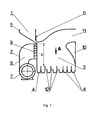
- the device for separating the mixed bulk material in a flowable medium contains: means for filling and conveying the mixed bulk material 1, a jet generator 2, a separation chamber 3, collecting container 4 for finished and Nachfr syndromeen.
- the means for filling and conveying the mixed bulk material 1 include bunker 5, which is provided with a slide 6 and a vibration device (not shown in the figures) for uniformly conveying the particles of the mixed bulk material into the separation chamber 3.
- the jet generator 2 is placed under the bunker 5 and consists of an air blower in the form of a blower (fan) 7, an air line 8 and a set of flat-aligned nozzles 9.
- the separation chamber 3 represents a rectangular, closed space whose characteristic dimension is its height.
- the height of the separation chamber 3 is designated H in the figures. Accordingly, the length of the separation chamber 3 is (1.3-1.5) H, and the width of the separation chamber 3 is (2.1-2.3) H.
- the Heilstromabweiser 10 is disposed on the inner surface of the rear wall of the separation chamber 3 with respect to the nozzles 9.
- the Heilstromabweiser 10 is formed in the form of a convex, wavy surface.
- a similar or similar deflector 10 can also be arranged on the upper wall and the side walls of the separation chamber 3.
- the bottom of the separation chamber 3 represents a totality of the collecting container 4 for finished fractions and post-fractions alternating in a specific sequence.
- the division of the collection containers 4 depending on the intended use for finished fractions and post-fractions is conditional and depends on the properties of the mixed bulk material to be processed from. An important role plays the serial number of the collecting container 4, starting from its distance from the front (nozzle) wall of the separation chamber. 3
- the collecting container 4 represent Scheiderinnen. They are arranged across the separation chamber 3 over its entire width. Each of the channels has a discharge mouth (the mouths are not shown in the figures).
- a device for forming the ascending air flow in the bottom of the separation chamber 3 is installed.
- the rising airflow forming means is formed as a whole of discharge ports 12 for passing the outside air.
- the discharge ports 12 are arranged between the second and the third, the third and the fourth, the fourth and the fifth collecting container 4.
- each discharge port 12 for passing the outside air is formed as a rectangular slit whose length is 2.1-2.3 of the height of the separation chamber 3 and whose width is 0.02-0.03 of the height of the separation chamber 3.
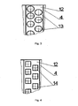
- Another version of the device is possible (s. Fig. 3 ) in which each discharge port 12 for passing the outside air in the form of rows of round holes 13 or (s. Fig. 4 ) rectangular holes 14 formed.
- the holes 13 and 14 are arranged in rows with a change step, ie, that the center distances of the holes 13 or 14 are different.
- the device works as follows.
- the mixed bulk material (eg grain) to be separated is conveyed into the bunker 5 of the means 1 for filling and conveying the mixed bulk material.
- the vibrating device and the jet generator 2 start up.
- the slider 6 is raised.
- the jet generator 2 ensures the promotion of uniform and practically horizontal air flow in the separation chamber 3 safe.
- the air flow from the jet generator 2 absorbs the flow of the grain falling freely from the bunker 5.
- the sampling cascade of the shallow air jets acts on the bulk material and divides the grains of the separable Materials in fractions that differ in density and aerodynamic properties.
- the denser particles having the better streamline shape fall into the region of the first header 4, and the less dense, large-area particles are dropped to the subsequent header 4.
- stones and heavy foreign matter come into the area of the first collecting container 4.
- the seed, the third collecting container food grain, the fourth and the fifth feed grain and the following containers the non-material fractions of the mixed bulk material.
- Volatile and powdery fractions are entrained by the air flow of the jet generator 2 and entrained from the separation chamber 3 via the opening 11 for discharging the air flow.
- the streamlined, wave-like, convex surface of the Lucasstromabweisers 10 contributes to the stabilization of the laminar (invertebrate) flow of the air flow in the separation chamber 3 at.
- the discharge ports 12 for passing the outside air are arranged between the collecting tanks 4 of the commercial fractions and ensure the air conditioning of the latter.
- liquid medium is formed.
- This flowable medium creates a dilution with respect to the atmosphere surrounding the device.
- the ejected rising outside air stream comes up from above via the discharge ports 12 up the particles of the commercial fractions of the mixed bulk material. These particles fall into the corresponding sump 4. This results in a counter-movement of the rising outside air flow and the particles of the commercial fractions of the mixed bulk material.
- the device is also effective in its application for precise multi-fraction separation of the mixed bulk, including simple and complex crops. This is very important for agriculture, for selection and breeding purposes, and in the treatment and preparation of seeds.
Landscapes
- Combined Means For Separation Of Solids (AREA)
Claims (9)
- Dispositif de séparation d'une substance en vrac mélangée (1), dans un milieu fluide, comprenant des moyens affectés au déversement et au convoyage de ladite substance en vrac mélangée (1) dans une chambre de séparation (3) ; un générateur de jets (2), occupant une position sous-jacente et muni de buses (9) et d'une soufflerie (7) ; ladite chambre de séparation (3) ; et des récipients (4) collecteurs de fractions et de post-fractions achevées,
caractérisé par le fait
que ledit dispositif est pourvu d'au moins un déflecteur (10) de courants d'air et d'un dispositif affecté à la formation d'un courant d'air ascendant, sachant que ledit déflecteur (10) de courants d'air est réalisé sous la forme d'une surface convexe située sur la paroi postérieure de la chambre de séparation (3) qui se trouve en vis-à-vis des buses (9), ledit dispositif, affecté à la formation du courant d'air ascendant, revêtant la forme d'orifices d'expulsion (12) dévolus au passage de l'air extérieur, et lesdits orifices d'expulsion (12) étant pratiqués dans le fond de ladite chambre de séparation (3), entre quelques récipients (4) collecteurs de fractions. - Dispositif selon la revendication 1,
caractérisé par le fait
que la surface convexe est de réalisation ondulée. - Dispositif selon la revendication 2,
caractérisé par le fait
que la longueur de la chambre de séparation représente 1,3 - 1,5 fois la hauteur de ladite chambre de séparation, et la largeur de ladite chambre de séparation représente 2,1 - 2,3 fois ladite hauteur de la chambre de séparation. - Dispositif selon la revendication 3,
caractérisé par le fait
que les orifices d'expulsion (12), dévolus au passage de l'air extérieur, sont pratiqués entre les deuxième, troisième et quatrième récipients (4) collecteurs de fractions et de post-fractions achevées. - Dispositif selon la revendication 4,
caractérisé par le fait
que chaque orifice d'expulsion (12), dévolu au passage de l'air extérieur, est réalisé en forme de fente et la largeur de cette fente représente 0,02 - 0,03 fois la hauteur de la chambre de séparation (3). - Dispositif selon la revendication 4,
caractérisé par le fait
que chaque orifice d'expulsion (12), dévolu au passage de l'air extérieur, est réalisé sous la forme de plusieurs trous (13, 14). - Dispositif selon la revendication 6,
caractérisé par le fait
que les trous (13, 14) présentent un agencement aligné. - Dispositif selon la revendication 7,
caractérisé par le fait
que les trous (13, 14) sont agencés en des rangées, avec pas de répartition alterné. - Dispositif selon la revendication 8,
caractérisé par le fait
que les trous (14) sont de réalisation rectangulaire.
Priority Applications (1)
| Application Number | Priority Date | Filing Date | Title |
|---|---|---|---|
| PL07834954T PL2186575T3 (pl) | 2007-03-09 | 2007-06-05 | Urządzenie do rozdzielania mieszanki materiału sypkiego w ośrodku strumieniowym |
Applications Claiming Priority (2)
| Application Number | Priority Date | Filing Date | Title |
|---|---|---|---|
| RU2007108668/03A RU2336131C1 (ru) | 2007-03-09 | 2007-03-09 | Устройство для сепарации сыпучей смеси в текучей среде |
| PCT/RU2007/000299 WO2008111868A1 (fr) | 2007-03-09 | 2007-06-05 | Dispositif de séparation d'un mélange pulvérulent dans un flux d'écoulement |
Publications (3)
| Publication Number | Publication Date |
|---|---|
| EP2186575A1 EP2186575A1 (fr) | 2010-05-19 |
| EP2186575A4 EP2186575A4 (fr) | 2012-12-12 |
| EP2186575B1 true EP2186575B1 (fr) | 2014-01-22 |
Family
ID=39759733
Family Applications (1)
| Application Number | Title | Priority Date | Filing Date |
|---|---|---|---|
| EP07834954.5A Not-in-force EP2186575B1 (fr) | 2007-03-09 | 2007-06-05 | Dispositif de séparation d'un mélange pulvérulent dans un flux d'écoulement |
Country Status (5)
| Country | Link |
|---|---|
| EP (1) | EP2186575B1 (fr) |
| ES (1) | ES2457818T3 (fr) |
| PL (1) | PL2186575T3 (fr) |
| RU (1) | RU2336131C1 (fr) |
| WO (1) | WO2008111868A1 (fr) |
Families Citing this family (9)
| Publication number | Priority date | Publication date | Assignee | Title |
|---|---|---|---|---|
| RU2391150C1 (ru) * | 2009-03-23 | 2010-06-10 | Общество с ограниченной ответственностью "Научно-производственная фирма "АЭРОМЕХ" (ООО "НПФ "АЭРОМЕХ") | Пневмосистема установки для воздушной сепарации сыпучей смеси в текучей среде |
| US9061321B2 (en) | 2013-05-31 | 2015-06-23 | Volodymyr Mytrofanovych Kosilov | Separating machine for separating loose mixtures in a fluid |
| AT515297B1 (de) | 2014-01-22 | 2015-08-15 | Wintersteiger Ag | Vorrichtung zum Abscheiden eines körnigen Guts aus einem Förderluftstrom |
| RU2672894C2 (ru) * | 2015-09-30 | 2018-11-20 | Владимир Степанович Сухин | Способ сепарации сыпучей смеси в текучей среде и устройство для его реализации |
| CN106824790A (zh) * | 2017-02-28 | 2017-06-13 | 四川理工学院 | 一种可控式多通道矿粒干法分选装置 |
| RU179365U1 (ru) * | 2017-04-26 | 2018-05-11 | Владимир Степанович Сухин | Универсальный аэродинамический сепаратор с дополнительной очисткой зернового материала |
| RU184205U1 (ru) * | 2018-05-22 | 2018-10-18 | Владимир Степанович Сухин | Аэродинамический сепаратор с дополнительной очисткой зернового материала |
| RU209903U1 (ru) * | 2021-11-08 | 2022-03-23 | Федеральное государственное бюджетное образовательное учреждение высшего образования «Волгоградский государственный технический университет» (ВолгГТУ) | Сетчатый пневмоклассификатор |
| WO2025075523A1 (fr) * | 2023-10-03 | 2025-04-10 | Владимир Митрофанович КОСИЛОВ | Dispositif de séparation de matériaux faiblement mobiles |
Family Cites Families (11)
| Publication number | Priority date | Publication date | Assignee | Title |
|---|---|---|---|---|
| FR975556A (fr) * | 1942-02-19 | 1951-03-07 | Traitement Ind Des Residus Urb | Procédé et installation pour le classement de matières hétérogènes et en particulier de déchets divers |
| US3823820A (en) * | 1972-04-26 | 1974-07-16 | G Sosson | Apparatus for separating comminuted electrical wire |
| GB2110959B (en) * | 1981-12-17 | 1985-09-04 | Faber Prest | Separation of mixtures in a wind tunnel |
| SU1321486A1 (ru) * | 1984-05-07 | 1987-07-07 | Всесоюзный Научно-Исследовательский Институт Гидромеханизации Нерудных Материалов | Устройство дл воздушной классификации дисперсных материалов |
| SU1645041A1 (ru) * | 1986-05-23 | 1991-04-30 | Войсковая Часть 44526 | Установка дл обогащени сыпучих материалов |
| SU1479141A1 (ru) | 1987-02-17 | 1989-05-15 | Ю. А. Иванов | Устройство дл сортировки сыпучих материалов по плотности |
| RU2130816C1 (ru) | 1997-12-10 | 1999-05-27 | Всероссийский научно-исследовательский институт механизации сельского хозяйства (ВИМ) | Способ сепарации сыпучих материалов и устройство для его осуществления |
| RU2132754C1 (ru) | 1998-02-24 | 1999-07-10 | Кубанский государственный аграрный университет | Устройство для сепарации сыпучей смеси |
| RU2132755C1 (ru) | 1998-07-28 | 1999-07-10 | Восточно-Сибирский государственный технологический университет | Способ сепарации сыпучих материалов и устройство для его реализации |
| RU2270061C2 (ru) * | 2003-12-04 | 2006-02-20 | Владимир Митрофанович Косилов | Устройство для сепарации сыпучей смеси в текучей среде |
| RU2262994C1 (ru) | 2004-04-13 | 2005-10-27 | Кубанский государственный аграрный университет | Сепаратор для сыпучих материалов |
-
2007
- 2007-03-09 RU RU2007108668/03A patent/RU2336131C1/ru not_active IP Right Cessation
- 2007-06-05 EP EP07834954.5A patent/EP2186575B1/fr not_active Not-in-force
- 2007-06-05 WO PCT/RU2007/000299 patent/WO2008111868A1/fr not_active Ceased
- 2007-06-05 PL PL07834954T patent/PL2186575T3/pl unknown
- 2007-06-05 ES ES07834954.5T patent/ES2457818T3/es active Active
Also Published As
| Publication number | Publication date |
|---|---|
| ES2457818T3 (es) | 2014-04-29 |
| EP2186575A4 (fr) | 2012-12-12 |
| RU2336131C1 (ru) | 2008-10-20 |
| PL2186575T3 (pl) | 2014-07-31 |
| EP2186575A1 (fr) | 2010-05-19 |
| WO2008111868A1 (fr) | 2008-09-18 |
Similar Documents
| Publication | Publication Date | Title |
|---|---|---|
| EP2186575B1 (fr) | Dispositif de séparation d'un mélange pulvérulent dans un flux d'écoulement | |
| DE3586428T2 (de) | Partikelklassierer. | |
| DE69030663T2 (de) | Verfahren und anlage zur sichtung von gegenständen, welche geringe dichteunterschiede aufweisen, mittels einer flotationsströmung | |
| EP3360613B1 (fr) | Dispositif de pressurage ou de concassage des céréales comestibles | |
| DE2552067A1 (de) | Saemaschine | |
| DE202017001636U1 (de) | Vorrichtung zum Abtrennen von Fremdstoffen von einem Schüttgut | |
| DE112016000194B4 (de) | Windkanalumlauf-Sichtvorrichtung für Schüttmaterial | |
| DE10196605B3 (de) | Vorrichtung zum Sortieren von Holzschnitzel in separate Fraktionen | |
| DE1507697A1 (de) | Verfahren und Vorrichtung zu rotierender Verarbeitung und Sortierung | |
| DE3626044C2 (fr) | ||
| DE1913708B2 (de) | Verfahren und Vorrichtung zum Trennen von körnigem Gut | |
| EP0020761B1 (fr) | Procede pour le tri de matiere en grains ou de semences et installations de tri | |
| DE2702019A1 (de) | Staubabscheider | |
| WO2019086354A1 (fr) | Dispositif de séparation | |
| DE1532086B2 (de) | Verfahren zum entrippen eines abwaerts bewegten stromes von tabakblaettern und vorrichtung zum ausueben des verfahrens | |
| DE69126028T2 (de) | Vorrichtung und verfahren zum fördern der gleichmässigkeit der dichte eines wirbelschichtmediums und/oder zum fördern der sichtung von materialien in einer wirbelschicht | |
| DE3407871A1 (de) | Verfahren und vorrichtung zur erzeugung eines massenstrom- oder volumenstromkonstanten gas-feststoffteilchen-freistrahls bestimmter geschwindigkeit | |
| CH623754A5 (en) | Air classifier | |
| DE102007020267B4 (de) | Vorrichtung zum Trennen einer lockeren Mischung in einem Fluidmedium | |
| DE1507686B1 (de) | Steigrohr-Windsichter | |
| DE1022409B (de) | Vorrichtung zum Trennen spezifisch schwererer und spezifisch leichterer Teile eines Koernergemenges, z.B. Getreide, Saemereien od. dgl. | |
| DE29709918U1 (de) | Vorrichtung zum Ausscheiden von Fein- und Leichtgut aus trockenem, rieselfähigem Schüttgut | |
| DE599366C (de) | Verfahren und Vorrichtung zur Aufbereitung von unklassierter Kohle und sonstigen Mineralien auf Luftherden mit Ruettelbewegung | |
| DE2636362A1 (de) | Verfahren und vorrichtung zum absondern auf pneumatischem wege von leichteren teilen aus einem schwerere teile enthaltenden teilchenstrom | |
| DE69228425T2 (de) | Anlage und verfahren zur sortierung mittels eines gleichmässigen wirbelbettes |
Legal Events
| Date | Code | Title | Description |
|---|---|---|---|
| PUAI | Public reference made under article 153(3) epc to a published international application that has entered the european phase |
Free format text: ORIGINAL CODE: 0009012 |
|
| 17P | Request for examination filed |
Effective date: 20100128 |
|
| AK | Designated contracting states |
Kind code of ref document: A1 Designated state(s): AT BE BG CH CY CZ DE DK EE ES FI FR GB GR HU IE IS IT LI LT LU LV MC MT NL PL PT RO SE SI SK TR |
|
| AX | Request for extension of the european patent |
Extension state: AL BA HR MK RS |
|
| R17P | Request for examination filed (corrected) |
Effective date: 20100128 |
|
| DAX | Request for extension of the european patent (deleted) | ||
| A4 | Supplementary search report drawn up and despatched |
Effective date: 20121109 |
|
| RIC1 | Information provided on ipc code assigned before grant |
Ipc: B07B 4/02 20060101AFI20121105BHEP |
|
| GRAP | Despatch of communication of intention to grant a patent |
Free format text: ORIGINAL CODE: EPIDOSNIGR1 |
|
| INTG | Intention to grant announced |
Effective date: 20130813 |
|
| GRAS | Grant fee paid |
Free format text: ORIGINAL CODE: EPIDOSNIGR3 |
|
| GRAA | (expected) grant |
Free format text: ORIGINAL CODE: 0009210 |
|
| AK | Designated contracting states |
Kind code of ref document: B1 Designated state(s): AT BE BG CH CY CZ DE DK EE ES FI FR GB GR HU IE IS IT LI LT LU LV MC MT NL PL PT RO SE SI SK TR |
|
| REG | Reference to a national code |
Ref country code: GB Ref legal event code: FG4D |
|
| REG | Reference to a national code |
Ref country code: CH Ref legal event code: EP |
|
| REG | Reference to a national code |
Ref country code: AT Ref legal event code: REF Ref document number: 650518 Country of ref document: AT Kind code of ref document: T Effective date: 20140215 |
|
| REG | Reference to a national code |
Ref country code: IE Ref legal event code: FG4D Free format text: LANGUAGE OF EP DOCUMENT: GERMAN |
|
| REG | Reference to a national code |
Ref country code: DE Ref legal event code: R096 Ref document number: 502007012738 Country of ref document: DE Effective date: 20140306 |
|
| REG | Reference to a national code |
Ref country code: RO Ref legal event code: EPE |
|
| REG | Reference to a national code |
Ref country code: ES Ref legal event code: FG2A Ref document number: 2457818 Country of ref document: ES Kind code of ref document: T3 Effective date: 20140429 |
|
| REG | Reference to a national code |
Ref country code: NL Ref legal event code: VDEP Effective date: 20140122 |
|
| REG | Reference to a national code |
Ref country code: LT Ref legal event code: MG4D |
|
| REG | Reference to a national code |
Ref country code: SK Ref legal event code: T3 Ref document number: E 16163 Country of ref document: SK |
|
| PG25 | Lapsed in a contracting state [announced via postgrant information from national office to epo] |
Ref country code: IS Free format text: LAPSE BECAUSE OF FAILURE TO SUBMIT A TRANSLATION OF THE DESCRIPTION OR TO PAY THE FEE WITHIN THE PRESCRIBED TIME-LIMIT Effective date: 20140522 Ref country code: LT Free format text: LAPSE BECAUSE OF FAILURE TO SUBMIT A TRANSLATION OF THE DESCRIPTION OR TO PAY THE FEE WITHIN THE PRESCRIBED TIME-LIMIT Effective date: 20140122 |
|
| REG | Reference to a national code |
Ref country code: PL Ref legal event code: T3 |
|
| PG25 | Lapsed in a contracting state [announced via postgrant information from national office to epo] |
Ref country code: NL Free format text: LAPSE BECAUSE OF FAILURE TO SUBMIT A TRANSLATION OF THE DESCRIPTION OR TO PAY THE FEE WITHIN THE PRESCRIBED TIME-LIMIT Effective date: 20140122 Ref country code: PT Free format text: LAPSE BECAUSE OF FAILURE TO SUBMIT A TRANSLATION OF THE DESCRIPTION OR TO PAY THE FEE WITHIN THE PRESCRIBED TIME-LIMIT Effective date: 20140522 Ref country code: SE Free format text: LAPSE BECAUSE OF FAILURE TO SUBMIT A TRANSLATION OF THE DESCRIPTION OR TO PAY THE FEE WITHIN THE PRESCRIBED TIME-LIMIT Effective date: 20140122 Ref country code: CY Free format text: LAPSE BECAUSE OF FAILURE TO SUBMIT A TRANSLATION OF THE DESCRIPTION OR TO PAY THE FEE WITHIN THE PRESCRIBED TIME-LIMIT Effective date: 20140122 Ref country code: FI Free format text: LAPSE BECAUSE OF FAILURE TO SUBMIT A TRANSLATION OF THE DESCRIPTION OR TO PAY THE FEE WITHIN THE PRESCRIBED TIME-LIMIT Effective date: 20140122 |
|
| PG25 | Lapsed in a contracting state [announced via postgrant information from national office to epo] |
Ref country code: LV Free format text: LAPSE BECAUSE OF FAILURE TO SUBMIT A TRANSLATION OF THE DESCRIPTION OR TO PAY THE FEE WITHIN THE PRESCRIBED TIME-LIMIT Effective date: 20140122 |
|
| REG | Reference to a national code |
Ref country code: DE Ref legal event code: R097 Ref document number: 502007012738 Country of ref document: DE |
|
| PG25 | Lapsed in a contracting state [announced via postgrant information from national office to epo] |
Ref country code: DK Free format text: LAPSE BECAUSE OF FAILURE TO SUBMIT A TRANSLATION OF THE DESCRIPTION OR TO PAY THE FEE WITHIN THE PRESCRIBED TIME-LIMIT Effective date: 20140122 Ref country code: EE Free format text: LAPSE BECAUSE OF FAILURE TO SUBMIT A TRANSLATION OF THE DESCRIPTION OR TO PAY THE FEE WITHIN THE PRESCRIBED TIME-LIMIT Effective date: 20140122 |
|
| PLBE | No opposition filed within time limit |
Free format text: ORIGINAL CODE: 0009261 |
|
| STAA | Information on the status of an ep patent application or granted ep patent |
Free format text: STATUS: NO OPPOSITION FILED WITHIN TIME LIMIT |
|
| 26N | No opposition filed |
Effective date: 20141023 |
|
| REG | Reference to a national code |
Ref country code: DE Ref legal event code: R119 Ref document number: 502007012738 Country of ref document: DE |
|
| PG25 | Lapsed in a contracting state [announced via postgrant information from national office to epo] |
Ref country code: MC Free format text: LAPSE BECAUSE OF FAILURE TO SUBMIT A TRANSLATION OF THE DESCRIPTION OR TO PAY THE FEE WITHIN THE PRESCRIBED TIME-LIMIT Effective date: 20140122 Ref country code: LU Free format text: LAPSE BECAUSE OF FAILURE TO SUBMIT A TRANSLATION OF THE DESCRIPTION OR TO PAY THE FEE WITHIN THE PRESCRIBED TIME-LIMIT Effective date: 20140605 |
|
| REG | Reference to a national code |
Ref country code: CH Ref legal event code: PL |
|
| REG | Reference to a national code |
Ref country code: DE Ref legal event code: R097 Ref document number: 502007012738 Country of ref document: DE Effective date: 20141023 |
|
| GBPC | Gb: european patent ceased through non-payment of renewal fee |
Effective date: 20140605 |
|
| REG | Reference to a national code |
Ref country code: IE Ref legal event code: MM4A |
|
| REG | Reference to a national code |
Ref country code: DE Ref legal event code: R119 Ref document number: 502007012738 Country of ref document: DE Effective date: 20150101 |
|
| PG25 | Lapsed in a contracting state [announced via postgrant information from national office to epo] |
Ref country code: DE Free format text: LAPSE BECAUSE OF NON-PAYMENT OF DUE FEES Effective date: 20150101 Ref country code: LI Free format text: LAPSE BECAUSE OF NON-PAYMENT OF DUE FEES Effective date: 20140630 Ref country code: CH Free format text: LAPSE BECAUSE OF NON-PAYMENT OF DUE FEES Effective date: 20140630 Ref country code: IE Free format text: LAPSE BECAUSE OF NON-PAYMENT OF DUE FEES Effective date: 20140605 |
|
| PG25 | Lapsed in a contracting state [announced via postgrant information from national office to epo] |
Ref country code: SI Free format text: LAPSE BECAUSE OF FAILURE TO SUBMIT A TRANSLATION OF THE DESCRIPTION OR TO PAY THE FEE WITHIN THE PRESCRIBED TIME-LIMIT Effective date: 20140122 Ref country code: GB Free format text: LAPSE BECAUSE OF NON-PAYMENT OF DUE FEES Effective date: 20140605 |
|
| REG | Reference to a national code |
Ref country code: FR Ref legal event code: PLFP Year of fee payment: 9 |
|
| PGFP | Annual fee paid to national office [announced via postgrant information from national office to epo] |
Ref country code: RO Payment date: 20150603 Year of fee payment: 9 Ref country code: TR Payment date: 20150601 Year of fee payment: 9 Ref country code: ES Payment date: 20150626 Year of fee payment: 9 Ref country code: SK Payment date: 20150604 Year of fee payment: 9 Ref country code: CZ Payment date: 20150604 Year of fee payment: 9 |
|
| PGFP | Annual fee paid to national office [announced via postgrant information from national office to epo] |
Ref country code: IT Payment date: 20150622 Year of fee payment: 9 Ref country code: PL Payment date: 20150601 Year of fee payment: 9 Ref country code: FR Payment date: 20150619 Year of fee payment: 9 Ref country code: AT Payment date: 20150619 Year of fee payment: 9 |
|
| PG25 | Lapsed in a contracting state [announced via postgrant information from national office to epo] |
Ref country code: MT Free format text: LAPSE BECAUSE OF FAILURE TO SUBMIT A TRANSLATION OF THE DESCRIPTION OR TO PAY THE FEE WITHIN THE PRESCRIBED TIME-LIMIT Effective date: 20140122 |
|
| PG25 | Lapsed in a contracting state [announced via postgrant information from national office to epo] |
Ref country code: BG Free format text: LAPSE BECAUSE OF FAILURE TO SUBMIT A TRANSLATION OF THE DESCRIPTION OR TO PAY THE FEE WITHIN THE PRESCRIBED TIME-LIMIT Effective date: 20140122 |
|
| PG25 | Lapsed in a contracting state [announced via postgrant information from national office to epo] |
Ref country code: GR Free format text: LAPSE BECAUSE OF FAILURE TO SUBMIT A TRANSLATION OF THE DESCRIPTION OR TO PAY THE FEE WITHIN THE PRESCRIBED TIME-LIMIT Effective date: 20140423 |
|
| PG25 | Lapsed in a contracting state [announced via postgrant information from national office to epo] |
Ref country code: BE Free format text: LAPSE BECAUSE OF FAILURE TO SUBMIT A TRANSLATION OF THE DESCRIPTION OR TO PAY THE FEE WITHIN THE PRESCRIBED TIME-LIMIT Effective date: 20140630 Ref country code: HU Free format text: LAPSE BECAUSE OF FAILURE TO SUBMIT A TRANSLATION OF THE DESCRIPTION OR TO PAY THE FEE WITHIN THE PRESCRIBED TIME-LIMIT; INVALID AB INITIO Effective date: 20070605 |
|
| PG25 | Lapsed in a contracting state [announced via postgrant information from national office to epo] |
Ref country code: RO Free format text: LAPSE BECAUSE OF NON-PAYMENT OF DUE FEES Effective date: 20160605 Ref country code: CZ Free format text: LAPSE BECAUSE OF NON-PAYMENT OF DUE FEES Effective date: 20160605 |
|
| REG | Reference to a national code |
Ref country code: AT Ref legal event code: MM01 Ref document number: 650518 Country of ref document: AT Kind code of ref document: T Effective date: 20160605 |
|
| REG | Reference to a national code |
Ref country code: SK Ref legal event code: MM4A Ref document number: E 16163 Country of ref document: SK Effective date: 20160605 |
|
| REG | Reference to a national code |
Ref country code: FR Ref legal event code: ST Effective date: 20170228 |
|
| PG25 | Lapsed in a contracting state [announced via postgrant information from national office to epo] |
Ref country code: FR Free format text: LAPSE BECAUSE OF NON-PAYMENT OF DUE FEES Effective date: 20160630 |
|
| PG25 | Lapsed in a contracting state [announced via postgrant information from national office to epo] |
Ref country code: AT Free format text: LAPSE BECAUSE OF NON-PAYMENT OF DUE FEES Effective date: 20160605 Ref country code: SK Free format text: LAPSE BECAUSE OF NON-PAYMENT OF DUE FEES Effective date: 20160605 |
|
| PG25 | Lapsed in a contracting state [announced via postgrant information from national office to epo] |
Ref country code: IT Free format text: LAPSE BECAUSE OF NON-PAYMENT OF DUE FEES Effective date: 20160605 |
|
| PG25 | Lapsed in a contracting state [announced via postgrant information from national office to epo] |
Ref country code: PL Free format text: LAPSE BECAUSE OF NON-PAYMENT OF DUE FEES Effective date: 20160605 |
|
| PG25 | Lapsed in a contracting state [announced via postgrant information from national office to epo] |
Ref country code: ES Free format text: LAPSE BECAUSE OF NON-PAYMENT OF DUE FEES Effective date: 20160606 |
|
| REG | Reference to a national code |
Ref country code: ES Ref legal event code: FD2A Effective date: 20181204 |
|
| PG25 | Lapsed in a contracting state [announced via postgrant information from national office to epo] |
Ref country code: TR Free format text: LAPSE BECAUSE OF NON-PAYMENT OF DUE FEES Effective date: 20160605 |