EP2186580A2 - Verfahren und Vorrichtung zum Pressen einer Manschette in eine Metallplatte und Manschette und Plattenelement - Google Patents
Verfahren und Vorrichtung zum Pressen einer Manschette in eine Metallplatte und Manschette und Plattenelement Download PDFInfo
- Publication number
- EP2186580A2 EP2186580A2 EP09176086A EP09176086A EP2186580A2 EP 2186580 A2 EP2186580 A2 EP 2186580A2 EP 09176086 A EP09176086 A EP 09176086A EP 09176086 A EP09176086 A EP 09176086A EP 2186580 A2 EP2186580 A2 EP 2186580A2
- Authority
- EP
- European Patent Office
- Prior art keywords
- collar
- plate
- pressing
- hole
- forming
- Prior art date
- Legal status (The legal status is an assumption and is not a legal conclusion. Google has not performed a legal analysis and makes no representation as to the accuracy of the status listed.)
- Withdrawn
Links
- 239000002184 metal Substances 0.000 title claims abstract description 11
- 238000000034 method Methods 0.000 title claims description 19
- 238000004080 punching Methods 0.000 claims description 5
- 230000000295 complement effect Effects 0.000 claims description 3
- 239000000463 material Substances 0.000 description 10
- 230000006835 compression Effects 0.000 description 3
- 238000007906 compression Methods 0.000 description 3
- 230000008719 thickening Effects 0.000 description 3
- 238000010079 rubber tapping Methods 0.000 description 2
- 238000013459 approach Methods 0.000 description 1
- 238000012986 modification Methods 0.000 description 1
- 230000004048 modification Effects 0.000 description 1
Images

Classifications
-
- B—PERFORMING OPERATIONS; TRANSPORTING
- B21—MECHANICAL METAL-WORKING WITHOUT ESSENTIALLY REMOVING MATERIAL; PUNCHING METAL
- B21D—WORKING OR PROCESSING OF SHEET METAL OR METAL TUBES, RODS OR PROFILES WITHOUT ESSENTIALLY REMOVING MATERIAL; PUNCHING METAL
- B21D28/00—Shaping by press-cutting; Perforating
- B21D28/24—Perforating, i.e. punching holes
- B21D28/26—Perforating, i.e. punching holes in sheets or flat parts
-
- B—PERFORMING OPERATIONS; TRANSPORTING
- B21—MECHANICAL METAL-WORKING WITHOUT ESSENTIALLY REMOVING MATERIAL; PUNCHING METAL
- B21D—WORKING OR PROCESSING OF SHEET METAL OR METAL TUBES, RODS OR PROFILES WITHOUT ESSENTIALLY REMOVING MATERIAL; PUNCHING METAL
- B21D19/00—Flanging or other edge treatment, e.g. of tubes
- B21D19/08—Flanging or other edge treatment, e.g. of tubes by single or successive action of pressing tools, e.g. vice jaws
- B21D19/10—Flanging or other edge treatment, e.g. of tubes by single or successive action of pressing tools, e.g. vice jaws working inwardly
-
- B—PERFORMING OPERATIONS; TRANSPORTING
- B21—MECHANICAL METAL-WORKING WITHOUT ESSENTIALLY REMOVING MATERIAL; PUNCHING METAL
- B21D—WORKING OR PROCESSING OF SHEET METAL OR METAL TUBES, RODS OR PROFILES WITHOUT ESSENTIALLY REMOVING MATERIAL; PUNCHING METAL
- B21D19/00—Flanging or other edge treatment, e.g. of tubes
- B21D19/08—Flanging or other edge treatment, e.g. of tubes by single or successive action of pressing tools, e.g. vice jaws
- B21D19/088—Flanging or other edge treatment, e.g. of tubes by single or successive action of pressing tools, e.g. vice jaws for flanging holes
-
- B—PERFORMING OPERATIONS; TRANSPORTING
- B21—MECHANICAL METAL-WORKING WITHOUT ESSENTIALLY REMOVING MATERIAL; PUNCHING METAL
- B21D—WORKING OR PROCESSING OF SHEET METAL OR METAL TUBES, RODS OR PROFILES WITHOUT ESSENTIALLY REMOVING MATERIAL; PUNCHING METAL
- B21D22/00—Shaping without cutting, by stamping, spinning, or deep-drawing
- B21D22/02—Stamping using rigid devices or tools
- B21D22/04—Stamping using rigid devices or tools for dimpling
-
- B—PERFORMING OPERATIONS; TRANSPORTING
- B21—MECHANICAL METAL-WORKING WITHOUT ESSENTIALLY REMOVING MATERIAL; PUNCHING METAL
- B21D—WORKING OR PROCESSING OF SHEET METAL OR METAL TUBES, RODS OR PROFILES WITHOUT ESSENTIALLY REMOVING MATERIAL; PUNCHING METAL
- B21D28/00—Shaping by press-cutting; Perforating
- B21D28/24—Perforating, i.e. punching holes
-
- B—PERFORMING OPERATIONS; TRANSPORTING
- B21—MECHANICAL METAL-WORKING WITHOUT ESSENTIALLY REMOVING MATERIAL; PUNCHING METAL
- B21D—WORKING OR PROCESSING OF SHEET METAL OR METAL TUBES, RODS OR PROFILES WITHOUT ESSENTIALLY REMOVING MATERIAL; PUNCHING METAL
- B21D35/00—Combined processes according to or processes combined with methods covered by groups B21D1/00 - B21D31/00
Definitions
- the invention relates to a method for pressing a collar in a metal plate, which involves pressing a collaring portion of the plate into a forming duct for the collar and making a hole in the plate.
- the invention also relates to a device for implementing the method, a collar formed in a metal plate by such a method or such a device, and a plate element provided with such a collar.
- Fitting components in fastening holes on metal plates often involves using so-called weld nuts as dollies for threaded fastening elements for the components.
- the fastening elements may be provided with a conical thread and a non-circular cross-section in order by plastic deformation to form the thread in the weld nut during the tightening stage of the fitting operation.
- weld nuts are expensive to use, since they have to be firmly pre-welded on the plate. It is therefore desirable to be able to dispense with the weld nut and instead form the plate with collars for fastening elements.
- the collaring portion is pressed down into the forming duct by a traction operation using a traction mandrel.
- a collaring method results in the plate becoming thinner at the collar, so the strength of the resulting threaded connection will not be sufficient.
- a so-called reducing process which gradually forms a collar by redistributing material in a region round the intended collar is certainly a known practice, but involves a large number of pressing steps.
- An object of the invention is to propose a method of the kind indicated in the introduction which can achieve a sufficiently strong collar by a minimum number of pressing steps.
- the plate is stretched in a region which comprises the collaring portion before the latter is pressed into the forming duct.
- This stretching provides that region with a surplus of plate material which in the subsequent pressing operation can be compressed towards the resulting collar so that the collar's plate thickness is caused to increase in at least the region of the mouth of the forming duct.
- the whole collaring operation can also be carried out in only two pressing steps, viz. a stretching step and a compression step.
- the stretching involves the forming of a concentric protrusion of the plate in said region.
- the forming of the protrusion may involve forming a central hollow in said region.
- the conical wall portion of the plate which converges towards the hollow may then be regarded as constituting a downward-pointing and therefore partly ready-made collaring portion of the plate.
- the pressing in of the collaring portion may be affected by pressure force on the protrusion.
- the material in the collaring portion will then be subject substantially to compression, thereby thickening the material.
- the hole may be formed by punching.
- the punching may be performed by a hole punch mounted on an upper element of a press tool during the downward pressing of the collaring portion.
- the hole punch may serve as a centre or drift for exerting pressure force against the inner surface of the collar, it will with advantage have a slightly diameter than that inner surface.
- a device for implementing the method is distinguished by a first press tool comprising a first upper element provided with a stretching profile and a first lower element provided with a stretching profile which cooperates therewith, and by a second press tool comprising a second upper element and a second lower element provided with a forming duct for the collar.
- the second upper element may be provided with said hole punch for making the hole.
- the invention also covers a plate element made by a method and a device as above.
- the pre-formed collar in the metal plate may be the first choice, such a plate element is inexpensive to make and may, where so required, be used as an alternative to a weld nut.
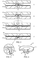
- FIGS. 1A-C depict a first press tool with an upper element 30 and a lower element 40, between which a metal plate 10 is to be subjected to a stretching operation.
- the upper element 30 and the lower element 40 are provided with mutually complementary stretching profiles comprising curved surfaces in a circular region R.
- the plate 10 is formed according to the curved surfaces so that it is subjected to area-increasing stretching in both tangential and radial directions in its initially planar region R.
- the curved surface of the lower element 40 has approximately the shape of an annular protrusion 42 with a central hollow 44.
- the complementary surface of the upper element 30 has an annular hollow 32 with a central protrusion 34.
- the upper side of the stretched plate 10 in the region R may be regarded as having an annular protrusion 12 and a central hollow 14.
- FIGS. 2A-C depict a second press tool with an upper element 50 and a lower element 60.
- the upper element 50 has on its planar pressing surface a punch 52 protruding downwards for punching out the hole 16.
- the lower element 60 has in its planar pressing surface a forming duct 62 situated opposite to the punch 52 to accommodate the pressed-down plate material and forming of the collar 18.
- the upper element 50 need not necessarily be provided with a punch 52 or some other perforating tool, as the hole 16 may also, within the scope of the invention, be pre-formed in the plate 10 (not depicted).
- the stretched plate 10 is placed in the position according to FIG. 2A between the upper element 50 and the lower element 60.
- a concentric collaring portion C of the stretched area R comprisng the hole 16 and at least part of the surrounding hollow 14, is situated above the mouth of the forming duct 62.
- Continued pressing will cause the collaring portion C to be pressed down into the forming duct 62 until the outside of the resulting collar 18 comes into contact with the rounded mouth 64 of the forming duct 62 ( FIG. 3 ) at a forming position approximately between the position in FIG. 2C and the position in FIG. 2D .
- the rounding radius at the mouth 64 may be relatively large for a good collaring result.
- This material thickening is advantageous in cases where the collar 18 is to be used in a threaded connection in conjunction with a self-tapping screw, e.g. a thread-pressing screw.
- the deformation hardening which occurs during the relocation of the plate material also increases the strength of the collar 18 and the portion adjacent to it of the plate 10.
- FIG. 4 illustrates the possibility of forming the collar 18 on a plate element 80 with a supporting flange 82.
- the plate element 80 may be provided beforehand with an internal thread on the collar 18, the example depicts it in the form of an unthreaded so-called weld nut usable in conjunction with a self-tapping screw.
- the plate element 80 may either be made separately by collar pressing of a circular or undepicted rectangular (material-saving) blank or be punched out from a larger plate provided with a plurality of pressed collars according to the invention.
- the invention is not necessarily limited to making circular or annular collars, as it is at least conceivable to provide the collar with some other cross-sectional profile, e.g. oval or polygonal.
Landscapes
- Engineering & Computer Science (AREA)
- Mechanical Engineering (AREA)
- Forging (AREA)
- Shaping Metal By Deep-Drawing, Or The Like (AREA)
Applications Claiming Priority (1)
| Application Number | Priority Date | Filing Date | Title |
|---|---|---|---|
| SE0802421A SE533132C2 (sv) | 2008-11-18 | 2008-11-18 | Förfarande och anordning för pressning av en krage i en metallplåt, samt krage och plåtbleck |
Publications (2)
| Publication Number | Publication Date |
|---|---|
| EP2186580A2 true EP2186580A2 (de) | 2010-05-19 |
| EP2186580A3 EP2186580A3 (de) | 2013-07-17 |
Family
ID=41796401
Family Applications (1)
| Application Number | Title | Priority Date | Filing Date |
|---|---|---|---|
| EP09176086.8A Withdrawn EP2186580A3 (de) | 2008-11-18 | 2009-11-16 | Verfahren und Vorrichtung zum Pressen einer Manschette in eine Metallplatte und Manschette und Plattenelement |
Country Status (2)
| Country | Link |
|---|---|
| EP (1) | EP2186580A3 (de) |
| SE (1) | SE533132C2 (de) |
Cited By (8)
| Publication number | Priority date | Publication date | Assignee | Title |
|---|---|---|---|---|
| JP2012071332A (ja) * | 2010-09-29 | 2012-04-12 | Aisin Aw Co Ltd | ボス付き円盤状部材の製造方法およびボス付き円盤状部材の製造装置 |
| US20130152656A1 (en) * | 2011-12-19 | 2013-06-20 | Ricoh Company, Ltd. | Thin plate burring processing method and thin plate female screw-forming method |
| EP2886731A1 (de) * | 2013-07-01 | 2015-06-24 | Simpson Strong-Tie Company, Inc. | Teil zur Verwendung in der Bauindustrie sowie Verfahren zur Herstellung davon |
| WO2016124528A1 (de) * | 2015-02-06 | 2016-08-11 | Thyssenkrupp Steel Europe Ag | Verfahren und vorrichtung zum auskragen eines werkstücks |
| US10265751B2 (en) | 2015-06-03 | 2019-04-23 | Thyssenkrupp Steel Europe Ag | Method and device for achieving long collar lengths |
| CN112317601A (zh) * | 2020-11-16 | 2021-02-05 | 张中海 | 一种汽车翼子板用冲孔设备 |
| US11098478B2 (en) | 2015-07-09 | 2021-08-24 | Simpson Strong-Tie Company Inc. | Fastening and alignment member |
| IT202100020507A1 (it) * | 2021-07-30 | 2023-01-30 | Biemmea Light Engineering & Tech S R L | Attrezzatura e metodo per lo stampaggio di materiale metallico in lastra sottile |
Citations (1)
| Publication number | Priority date | Publication date | Assignee | Title |
|---|---|---|---|---|
| US1699361A (en) * | 1926-02-17 | 1929-01-15 | Karmazin John | Method of forming integral tubular projections on a sheet of metal |
Family Cites Families (5)
| Publication number | Priority date | Publication date | Assignee | Title |
|---|---|---|---|---|
| DE3042158C2 (de) * | 1980-11-08 | 1982-11-25 | C. Behrens Ag, 3220 Alfeld | Einrichtung zum Herstellen von Durchzügen an Werkstücken auf einer Schneidpresse |
| JPH0724871B2 (ja) * | 1988-03-31 | 1995-03-22 | 松下電器産業株式会社 | 熱交換器用フィンのカラー成形法及び金型 |
| JPH04123828A (ja) * | 1990-09-13 | 1992-04-23 | Hidaka Seiki Kk | 熱交換器用フィンの製造金型 |
| JP2006007253A (ja) * | 2004-06-24 | 2006-01-12 | Kato Seisakusho:Kk | プレス加工品及びその製造方法 |
| JP2007275976A (ja) * | 2006-04-11 | 2007-10-25 | Fujifilm Corp | プレス金型、バーリング加工方法、プレス加工品の製造方法およびプレス加工品 |
-
2008
- 2008-11-18 SE SE0802421A patent/SE533132C2/sv not_active IP Right Cessation
-
2009
- 2009-11-16 EP EP09176086.8A patent/EP2186580A3/de not_active Withdrawn
Patent Citations (1)
| Publication number | Priority date | Publication date | Assignee | Title |
|---|---|---|---|---|
| US1699361A (en) * | 1926-02-17 | 1929-01-15 | Karmazin John | Method of forming integral tubular projections on a sheet of metal |
Cited By (12)
| Publication number | Priority date | Publication date | Assignee | Title |
|---|---|---|---|---|
| JP2012071332A (ja) * | 2010-09-29 | 2012-04-12 | Aisin Aw Co Ltd | ボス付き円盤状部材の製造方法およびボス付き円盤状部材の製造装置 |
| US20130152656A1 (en) * | 2011-12-19 | 2013-06-20 | Ricoh Company, Ltd. | Thin plate burring processing method and thin plate female screw-forming method |
| EP2886731A1 (de) * | 2013-07-01 | 2015-06-24 | Simpson Strong-Tie Company, Inc. | Teil zur Verwendung in der Bauindustrie sowie Verfahren zur Herstellung davon |
| WO2016124528A1 (de) * | 2015-02-06 | 2016-08-11 | Thyssenkrupp Steel Europe Ag | Verfahren und vorrichtung zum auskragen eines werkstücks |
| DE102015101717A1 (de) * | 2015-02-06 | 2016-08-11 | Thyssenkrupp Ag | Verfahren und Vorrichtung zum Auskragen eines Werkstücks |
| CN107206452A (zh) * | 2015-02-06 | 2017-09-26 | 蒂森克虏伯钢铁欧洲股份公司 | 用于在工件上产生套环的方法和装置 |
| US10118211B2 (en) | 2015-02-06 | 2018-11-06 | Thyssenkrupp Steel Europe Ag | Method and device for forming a collar on a workpiece |
| US10265751B2 (en) | 2015-06-03 | 2019-04-23 | Thyssenkrupp Steel Europe Ag | Method and device for achieving long collar lengths |
| US11098478B2 (en) | 2015-07-09 | 2021-08-24 | Simpson Strong-Tie Company Inc. | Fastening and alignment member |
| US11965329B2 (en) | 2015-07-09 | 2024-04-23 | Simpson Strong-Tie Company, Inc. | Fastening and alignment member |
| CN112317601A (zh) * | 2020-11-16 | 2021-02-05 | 张中海 | 一种汽车翼子板用冲孔设备 |
| IT202100020507A1 (it) * | 2021-07-30 | 2023-01-30 | Biemmea Light Engineering & Tech S R L | Attrezzatura e metodo per lo stampaggio di materiale metallico in lastra sottile |
Also Published As
| Publication number | Publication date |
|---|---|
| SE0802421A1 (sv) | 2010-05-19 |
| SE533132C2 (sv) | 2010-07-06 |
| EP2186580A3 (de) | 2013-07-17 |
Similar Documents
| Publication | Publication Date | Title |
|---|---|---|
| EP2186580A2 (de) | Verfahren und Vorrichtung zum Pressen einer Manschette in eine Metallplatte und Manschette und Plattenelement | |
| MX2012004567A (es) | Sujetador de perno de remache. | |
| US7165310B2 (en) | Method for connecting two members | |
| KR20170105440A (ko) | 기능적 요소를 시트 금속 부재에 부착하는 방법 | |
| CN106102948A (zh) | 具有多个增厚部分的板状成型体的制造方法及具有多个增厚部的板状成型体 | |
| KR101557392B1 (ko) | 레버 및 이의 제조방법 | |
| WO2014034211A1 (ja) | 高強度鋼板用ピアスナット | |
| KR20090028059A (ko) | 탭 플레이트의 제조방법 | |
| JP6539562B2 (ja) | フランジの成形方法 | |
| US8402632B2 (en) | Method for crimping an insert in a support with two superposed panels | |
| US20090029247A1 (en) | Side terminal and insert, method and apparatus for manufacturing same | |
| JP2006297455A (ja) | 圧入ナットおよびその製造方法 | |
| JP2020029876A (ja) | バーリング締結方法、バーリング締結構造およびバーリングパンチ | |
| JP5097769B2 (ja) | リング状部材の製造方法 | |
| JP2010227988A (ja) | 鋼管の拡管成形方法および拡管成形装置 | |
| US20090175675A1 (en) | Method for inserting connecting elements in metal sheets and connection between a metal sheet and a connecting element | |
| JP7587837B2 (ja) | 板状ワーク積層体へのピアスナットの結合方法 | |
| CN107110192B (zh) | 用于固定在板材处的螺母 | |
| JP2004322104A (ja) | 絞り成形金型および絞り成形方法 | |
| JPH09151927A (ja) | セルフピアシングスタッドの金属パネルへの固着方法、セルフピアシングスタッドの金属パネルへの固着用プランジャ−ダイボタン・アセンブリー及びセルフピアシングスタッド | |
| CN107503403B (zh) | 一种用于水龙头安装的锁紧装置 | |
| CN2390716Y (zh) | 模具脱料弹簧装置 | |
| CN224149937U (zh) | 一种连接螺栓及复合材料连接组件 | |
| CN112775276A (zh) | 薄材翻边螺纹孔的冲孔工艺 | |
| CN207212458U (zh) | 一种汽车排气管衔接固定用的法兰 |
Legal Events
| Date | Code | Title | Description |
|---|---|---|---|
| PUAI | Public reference made under article 153(3) epc to a published international application that has entered the european phase |
Free format text: ORIGINAL CODE: 0009012 |
|
| AK | Designated contracting states |
Kind code of ref document: A2 Designated state(s): AT BE BG CH CY CZ DE DK EE ES FI FR GB GR HR HU IE IS IT LI LT LU LV MC MK MT NL NO PL PT RO SE SI SK SM TR |
|
| PUAL | Search report despatched |
Free format text: ORIGINAL CODE: 0009013 |
|
| AK | Designated contracting states |
Kind code of ref document: A3 Designated state(s): AT BE BG CH CY CZ DE DK EE ES FI FR GB GR HR HU IE IS IT LI LT LU LV MC MK MT NL NO PL PT RO SE SI SK SM TR |
|
| RIC1 | Information provided on ipc code assigned before grant |
Ipc: B21D 28/26 20060101AFI20130613BHEP Ipc: B21D 19/08 20060101ALI20130613BHEP Ipc: B21D 28/24 20060101ALI20130613BHEP Ipc: B21D 22/04 20060101ALI20130613BHEP |
|
| 17P | Request for examination filed |
Effective date: 20140117 |
|
| RBV | Designated contracting states (corrected) |
Designated state(s): AT BE BG CH CY CZ DE DK EE ES FI FR GB GR HR HU IE IS IT LI LT LU LV MC MK MT NL NO PL PT RO SE SI SK SM TR |
|
| 17Q | First examination report despatched |
Effective date: 20151106 |
|
| STAA | Information on the status of an ep patent application or granted ep patent |
Free format text: STATUS: THE APPLICATION IS DEEMED TO BE WITHDRAWN |
|
| 18D | Application deemed to be withdrawn |
Effective date: 20160317 |