EP2186588B1 - Scie circulaire et scie à onglet - Google Patents
Scie circulaire et scie à onglet Download PDFInfo
- Publication number
- EP2186588B1 EP2186588B1 EP09013856.1A EP09013856A EP2186588B1 EP 2186588 B1 EP2186588 B1 EP 2186588B1 EP 09013856 A EP09013856 A EP 09013856A EP 2186588 B1 EP2186588 B1 EP 2186588B1
- Authority
- EP
- European Patent Office
- Prior art keywords
- carrier
- additional
- workpiece
- attached
- saw
- Prior art date
- Legal status (The legal status is an assumption and is not a legal conclusion. Google has not performed a legal analysis and makes no representation as to the accuracy of the status listed.)
- Active
Links
Images

Classifications
-
- B—PERFORMING OPERATIONS; TRANSPORTING
- B23—MACHINE TOOLS; METAL-WORKING NOT OTHERWISE PROVIDED FOR
- B23D—PLANING; SLOTTING; SHEARING; BROACHING; SAWING; FILING; SCRAPING; LIKE OPERATIONS FOR WORKING METAL BY REMOVING MATERIAL, NOT OTHERWISE PROVIDED FOR
- B23D45/00—Sawing machines or sawing devices with circular saw blades or with friction saw discs
- B23D45/04—Sawing machines or sawing devices with circular saw blades or with friction saw discs with a circular saw blade or the stock carried by a pivoted lever
- B23D45/042—Sawing machines or sawing devices with circular saw blades or with friction saw discs with a circular saw blade or the stock carried by a pivoted lever with the saw blade carried by a pivoted lever
- B23D45/046—Sawing machines or sawing devices with circular saw blades or with friction saw discs with a circular saw blade or the stock carried by a pivoted lever with the saw blade carried by a pivoted lever the pivoted lever being mounted on a carriage
- B23D45/048—Sawing machines or sawing devices with circular saw blades or with friction saw discs with a circular saw blade or the stock carried by a pivoted lever with the saw blade carried by a pivoted lever the pivoted lever being mounted on a carriage the saw blade being adjustable according to angle of cut
-
- B—PERFORMING OPERATIONS; TRANSPORTING
- B23—MACHINE TOOLS; METAL-WORKING NOT OTHERWISE PROVIDED FOR
- B23D—PLANING; SLOTTING; SHEARING; BROACHING; SAWING; FILING; SCRAPING; LIKE OPERATIONS FOR WORKING METAL BY REMOVING MATERIAL, NOT OTHERWISE PROVIDED FOR
- B23D47/00—Sawing machines or sawing devices working with circular saw blades, characterised only by constructional features of particular parts
- B23D47/02—Sawing machines or sawing devices working with circular saw blades, characterised only by constructional features of particular parts of frames; of guiding arrangements for work-table or saw-carrier
- B23D47/025—Sawing machines or sawing devices working with circular saw blades, characterised only by constructional features of particular parts of frames; of guiding arrangements for work-table or saw-carrier of tables
Definitions
- the invention relates to a miter saw with the features of the preamble of claim 1.
- the known miter saw from which the invention proceeds ( GB-A-2 446 317 ), has a support with which it stands on a base, such as a workbench.
- the support itself forms marginal bearing surfaces on the edge.
- a rotatably mounted about a vertical axis rotary table is embedded. Together with the lateral bearing surfaces of this turntable forms a workpiece support surface.
- the workpiece support surface in the region of the turntable on a dipping slot for the ring gear of a saw blade.
- miter saw is located on the turntable, which forms part of the carrier, a holder for a saw unit, which is arranged above the workpiece support surface and has a drive motor and a driven therefrom saw blade.
- This sawing unit defines a sawing direction with the plane of the saw blade. This is reflected in the orientation of the immersion slot in the workpiece support surface again.
- the saw unit can be pivoted on the holder about a transverse axis, from a raised rest position to a lowered saw position and vice versa. With this movement of the saw blade, a workpiece located on the workpiece support surface can be cut off - cut off.
- the saw blade can here cut through the workpiece not only due to the pivoting movement about the transverse axis, but also due to a sliding movement perpendicular to the transverse axis and parallel to the workpiece support surface.
- the well-known miter saw is thus a combined miter, miter and tension saw. It is further characterized in that the turntable has a small diameter, but has a cantilever arm with immersion slot continued therein.
- the teaching of the invention can be realized in a miter saw with a turntable with boom as well as in a crosscut and miter saw with a turntable without boom ( DE-A-29 29 932 ) and in a miter saw in the form of a radial arm saw without or with height adjustment ( US-A-4,152,961 ).
- the workpiece support surface in stateauxetticardi defined at located in the central home position sawing unit a certain depth and transverse to the workinggeschnittcardi in this position of the sawing a certain width.
- the workpiece can be considerably larger than the workpiece support surface, in particular substantially wider or substantially deeper in terms of its dimensions. In this case, the workpiece is not optimal, the saw cut in the workpiece can not be performed as precisely as you really want.
- each one an additional surface forming additional carrier attached by the for the support of a workpiece effective width of the workpiece support surface is increased.
- the additional surface of the carrier mounted on the additional carrier relative to the carrier between a near the carrier near base position and a distance from the carrier as far as possible removed distance adjustable.
- the additional surface in the basic position at least a considerable part behind the cross line. In the basic position, therefore, a significant part of the additional area for the support of the workpiece is unused. In the basic position but also only workpieces are regularly processed with correspondingly appropriate, small dimensions.
- the additional carrier with the additional surface is moved into the distance position or a position located between the basic position and the distance position. This is the unused in the basic position Part of the additional area in the area in front of the transverse line defined by the workpiece stop. This additional surface acts here on the support of the workpiece, which is created on the workpiece stop, with.
- a large workpiece is thus supported much better, namely with a larger additional surface than before.
- the additional surface on the additional carrier moves when moving from the basic position in the distance position exactly where it is needed for a wide and deep workpiece.
- a "significant part" of the additional area means at least 25%, preferably 30% to 50%, of the total additional area.
- the additional carrier is mounted on the carrier in such a way that it can be adjusted from its basic position into its distance position by an obliquely outwardly and forwardly directed movement away from the workpiece stop.
- An alternative to a bar displacement guide is a pivoting guide ( DE-U-20 2006 012 601 ) or a parallelogram panning guide.
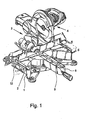
- Fig. 1 shows the basic structure of a miter saw according to the invention, here in the embodiment of a combined miter, miter and tension saw.
- the train function is not a mandatory requirement for the realization of the doctrine.
- miter saw shows a support 1, which forms a Maschinen Swissausßageßwashe 2.
- a holder 3 for a above the workpiece support surface 2 arranged, a shegeschnittcardi defining saw unit 4.
- a turntable 5 is inserted into the carrier 1, which is rotatably mounted in the carrier 1 about a vertical axis.
- a workpiece stop 6 Affixed to the carrier 1 is a workpiece stop 6 on which a workpiece 7 (FIG. Fig. 2-5 ) is created.
- the workpiece stop 6 extends transversely to the direction of sawing, if this is in befindlichem in the central home position saw unit 4 ( Fig. 1 ) Are defined.
- the workpiece support surface 2 has a certain depth in saw-cutting time, indicated in FIG Fig. 2 , And across the shegeschnittides a certain width.
- the depth of the workpiece support surface 2 is defined without the boom arm 8 of the turntable 5.
- Fig. 1 It can be seen that on the carrier 1 at least on one transverse side, in fact on both transverse sides, an additional surface 10 forming additional carrier 11 can be attached, by which the support of a workpiece 7 effective width is increased.
- Fig. 1 can be seen at the laterally indicated jacks 12, in the support rods 13 of an additional carrier 11 can be inserted.
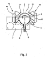
- Fig. 2 to 5 each show right and left of the carrier 1 corresponding additional carrier 11 with additional surfaces 10 and corresponding support rods 13th
- auxiliary carrier 11 is attachable, through which the effective width for the support of a workpiece 7 can be increased.
- the additional surfaces 10 of the carrier 1 mounted on the additional carrier 11 is relative to the carrier 1 between a carrier 1 near the base position and a distance from the carrier 1 as far as possible removed distance adjustable.
- the additional surface 10 is in the basic position at least to a considerable extent behind the transverse line defined by the workpiece stop 6 and in the distance position as far as possible or completely in front of the transverse line.
- Fig. 2 are located on the right and left of the carrier 1 arranged additional carrier 11 with their additional surfaces 10 in basic position. It can be seen that the large workpiece 7, indicated by the dot-dashed circle, has a large, unsupported surface. It can also be seen that a considerable part of the additional surfaces 10 of the two additional carriers 11 are located behind the transverse line defined by the workpiece stop 6.
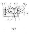
- Fig. 3 shows the two additional carrier 11 with their additional surfaces 10 in the respective distance position.
- the effective width and depth of the workpiece support surface 2 has increased significantly.
- dash-dotted lines are indicated by a circle, which surface of the workpiece 7 is not supported. That's a lot less than in Fig. 2 ,
- Fig. 2 and 3 illustrated embodiment shows that the substantial part of the additional surface 10 is at least 25%, preferably 30% to 50%, of the additional surface 10.
- FIG. 2 and 3 illustrated embodiment also shows a particularly expedient construction with a Stangen-Verschiebessel with support rods It is provided that the additional carrier 11 and here both additional carrier 11 so on the support 1, in the illustrated embodiment on the transverse side of the carrier 1, mounted so that it obliquely away from the basic position by a workpiece stop 6 away outside and after the directional movement is adjustable in its distance position.
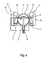
- the jacks 12 are for the support rods 13 of the additional carrier 11 is not on the transverse sides of the carrier 1, but at the front. Due to the clever L-shape of the additional surfaces 10 of the additional carrier 11 but also here has the same effect of "activating" in the basic position of unused parts of the additional surfaces 10. Thus, in this embodiment, when moving the additional carrier 11 in the distance position and the effective width of the Workpiece support surface 2 perfectly enlarged.
Landscapes
- Engineering & Computer Science (AREA)
- Mechanical Engineering (AREA)
- Sawing (AREA)
Claims (6)
- Scie circulaire et à onglet,
comportant un support (1), qui constitue une surface d'appui (2) de pièce d'usinage ainsi qu'une fixation (3) attachée au support (1) pour un outil de sciage (4) définissant une direction d'un trait de scie, disposé au-dessus de la surface d'appui (2) de pièce d'usinage, avec une butée d'appui (6), pour une pièce d'usinage (7), fixée au support (1), dans une position médiane de l'outil de sciage (4), et s'étendant transversalement par rapport à la direction du trait de scie, sur la surface d'appui (2) de pièce d'usinage,
dans laquelle la surface d'appui (2) de la pièce d'usinage présente, dans la direction du trait de scie, lorsque l'outil de sciage (4) se trouve dans son positionnement de base, une certaine profondeur et dans la direction transversale par rapport à la direction du trait de scie, une certaine largeur,
lorsque l'outil de sciage (4) se trouve dans son positionnement de base,
dans laquelle le support (1), est pourvu, au moins d'un côté, d'une surface supplémentaire (10) formant un support complémentaire (11), grâce auquel, la profondeur et/ou la largeur utile pour le maintien d'une pièce d'usinage (7),
peuvent être agrandies,
dans laquelle la surface supplémentaire (10) fixée du support complémentaire (11) du support (1), est réglable entre une position de base proche du support (1) et une position distante éventuellement plus éloignée, et
dans laquelle la surface supplémentaire (10) se trouve dans la position de base, pour une certaine partie, en arrière de la ligne transversale définie par la butée d'appui (6) de la pièce d'usinage,
caractérisée en ce que,
la surface supplémentaire (10) se trouve, dans sa position de base, pour une part importante derrière la ligne transversale définie par la butée d'appui (6) et dans la position distante, bien d'avantage ou complètement devant la ligne transversale, et
que le support complémentaire (11) est attaché au support (1) de telle manière qu'il est réglable de sa position de base vers sa position distante, par un déplacement orienté en oblique, vers l'extérieur et vers l'avant, de la butée d'appui (6). - Scie circulaire et à onglet, selon la revendication 1, caractérisée en ce que la part importante de la surface supplémentaire (10) comprend au moins 25%, de préférence 30% à 50% de la surface (10).
- Scie circulaire et à onglet, selon les revendications 1 ou 2, caractérisée en ce que, le support complémentaire (10) est solidaire du côté latéral du support (1).
- Scie circulaire et à onglet selon l'une des revendications 1 à 3, caractérisée en ce que le support complémentaire (11) est fixé au support (1) au moyen de tiges coulissantes.
- Scie circulaire et à onglet selon l'une des revendications 1 à 3, caractérisée en ce que le support complémentaire (11) est fixé au support (1) au moyen d'un dispositif de guidage pivotant, en particulier un dispositif à parallélogramme.
- Scie circulaire et à onglet selon l'une des revendications 1 à 5, caractérisée en ce que le support complémentaire (11) est fixé au support (1) de façon amovible.
Applications Claiming Priority (1)
| Application Number | Priority Date | Filing Date | Title |
|---|---|---|---|
| DE200820015018 DE202008015018U1 (de) | 2008-11-12 | 2008-11-12 | Kapp- und Gehrungssäge |
Publications (2)
| Publication Number | Publication Date |
|---|---|
| EP2186588A1 EP2186588A1 (fr) | 2010-05-19 |
| EP2186588B1 true EP2186588B1 (fr) | 2015-01-07 |
Family
ID=41800586
Family Applications (1)
| Application Number | Title | Priority Date | Filing Date |
|---|---|---|---|
| EP09013856.1A Active EP2186588B1 (fr) | 2008-11-12 | 2009-11-04 | Scie circulaire et scie à onglet |
Country Status (2)
| Country | Link |
|---|---|
| EP (1) | EP2186588B1 (fr) |
| DE (1) | DE202008015018U1 (fr) |
Citations (1)
| Publication number | Priority date | Publication date | Assignee | Title |
|---|---|---|---|---|
| US20040079214A1 (en) * | 2001-02-08 | 2004-04-29 | Meredith Daryl S. | Miter saw |
Family Cites Families (6)
| Publication number | Priority date | Publication date | Assignee | Title |
|---|---|---|---|---|
| US4152961A (en) | 1978-01-18 | 1979-05-08 | The Singer Company | Radial saw |
| DE2929932A1 (de) | 1978-08-10 | 1980-02-21 | Liliana Ottaviani | Drehtischvorrichtung zum schneiden von platten, profilen und aehnlichem mit einer kreissaege |
| EP1604764A1 (fr) | 2001-02-08 | 2005-12-14 | BLACK & DECKER INC. | Dispositif de protection pour une lame de scie à onglet |
| GB2446317B (en) * | 2004-04-15 | 2008-09-10 | Milwaukee Electric Tool Corp | A power tool |
| DE202006001892U1 (de) | 2006-02-03 | 2006-04-13 | Jochimsen, Hans-Peter | Kappsäge mit Werkstückhalter |
| DE202006012601U1 (de) | 2006-08-15 | 2006-11-09 | Metabowerke Gmbh | Kapp- und Gehrungssäge mit einem Drehtisch |
-
2008
- 2008-11-12 DE DE200820015018 patent/DE202008015018U1/de not_active Expired - Lifetime
-
2009
- 2009-11-04 EP EP09013856.1A patent/EP2186588B1/fr active Active
Patent Citations (1)
| Publication number | Priority date | Publication date | Assignee | Title |
|---|---|---|---|---|
| US20040079214A1 (en) * | 2001-02-08 | 2004-04-29 | Meredith Daryl S. | Miter saw |
Also Published As
| Publication number | Publication date |
|---|---|
| EP2186588A1 (fr) | 2010-05-19 |
| DE202008015018U1 (de) | 2010-04-08 |
Similar Documents
| Publication | Publication Date | Title |
|---|---|---|
| EP3581310B1 (fr) | Machine à scier pour coupes d'onglet | |
| EP1557231B1 (fr) | Scie pivotante avec collecteur de poussière | |
| EP0598248B1 (fr) | Scie circulaire portative à moteur électrique | |
| DE4106635C1 (fr) | ||
| DE3511498A1 (de) | Vorrichtung zur bearbeitung von pfosten oder sprossen fuer fenster oder tueren | |
| EP0615807A2 (fr) | Scie de précision à table ayant une rigidité de torsion améliorée des éléments de structure | |
| EP2213398B1 (fr) | Scie à onglet du type combiné | |
| EP1839791B1 (fr) | Scie circulaire à table | |
| EP2186588B1 (fr) | Scie circulaire et scie à onglet | |
| DE29910173U1 (de) | Stichsäge | |
| DE202006012601U1 (de) | Kapp- und Gehrungssäge mit einem Drehtisch | |
| DE3347920A1 (de) | Saegeeinrichtung | |
| EP0109632A1 (fr) | Couche carter pour scie circulaire | |
| DE29506017U1 (de) | Stichsäge | |
| DE102004052130B3 (de) | Sägevorrichtung mit Auflagefläche für Baumstämme und mit einer quer zu dieser an einer Führung verstellbaren Anschlagkonsole | |
| DE2910337C2 (de) | Kombinierte Tisch- und Gehrungssäge | |
| EP2198999B1 (fr) | Machine-outil, notamment scie circulaire et à onglet | |
| EP1518628B1 (fr) | Scie pivotante, en particulier pour le travail du bois | |
| DE202009005542U1 (de) | Kappsäge mit Neigungsverstellung | |
| DE202006012341U1 (de) | Kappsäge mit Längssägefunktion | |
| DE2925401C2 (de) | Stichsäge mit Motorantrieb | |
| DE102006017060B3 (de) | Aufsatzeinrichtung für einen Sägentisch | |
| EP0299227B1 (fr) | Scie circulaire à froid à lame de scie mobile vers le haut à travers une plaque de support de dessous d'une table de support | |
| EP1857207B1 (fr) | Scie à onglet transportable | |
| DE2161358A1 (de) | Einrichtung an Zapfenschneidmaschinen |
Legal Events
| Date | Code | Title | Description |
|---|---|---|---|
| PUAI | Public reference made under article 153(3) epc to a published international application that has entered the european phase |
Free format text: ORIGINAL CODE: 0009012 |
|
| AK | Designated contracting states |
Kind code of ref document: A1 Designated state(s): AT BE BG CH CY CZ DE DK EE ES FI FR GB GR HR HU IE IS IT LI LT LU LV MC MK MT NL NO PL PT RO SE SI SK SM TR |
|
| AX | Request for extension of the european patent |
Extension state: AL BA RS |
|
| 17P | Request for examination filed |
Effective date: 20100615 |
|
| GRAP | Despatch of communication of intention to grant a patent |
Free format text: ORIGINAL CODE: EPIDOSNIGR1 |
|
| INTG | Intention to grant announced |
Effective date: 20140724 |
|
| GRAS | Grant fee paid |
Free format text: ORIGINAL CODE: EPIDOSNIGR3 |
|
| GRAA | (expected) grant |
Free format text: ORIGINAL CODE: 0009210 |
|
| AK | Designated contracting states |
Kind code of ref document: B1 Designated state(s): AT BE BG CH CY CZ DE DK EE ES FI FR GB GR HR HU IE IS IT LI LT LU LV MC MK MT NL NO PL PT RO SE SI SK SM TR |
|
| REG | Reference to a national code |
Ref country code: GB Ref legal event code: FG4D Free format text: NOT ENGLISH |
|
| REG | Reference to a national code |
Ref country code: CH Ref legal event code: EP |
|
| REG | Reference to a national code |
Ref country code: IE Ref legal event code: FG4D Free format text: LANGUAGE OF EP DOCUMENT: GERMAN |
|
| REG | Reference to a national code |
Ref country code: AT Ref legal event code: REF Ref document number: 705340 Country of ref document: AT Kind code of ref document: T Effective date: 20150215 |
|
| REG | Reference to a national code |
Ref country code: DE Ref legal event code: R096 Ref document number: 502009010445 Country of ref document: DE Effective date: 20150219 |
|
| REG | Reference to a national code |
Ref country code: NL Ref legal event code: VDEP Effective date: 20150107 |
|
| REG | Reference to a national code |
Ref country code: LT Ref legal event code: MG4D |
|
| PG25 | Lapsed in a contracting state [announced via postgrant information from national office to epo] |
Ref country code: HR Free format text: LAPSE BECAUSE OF FAILURE TO SUBMIT A TRANSLATION OF THE DESCRIPTION OR TO PAY THE FEE WITHIN THE PRESCRIBED TIME-LIMIT Effective date: 20150107 Ref country code: ES Free format text: LAPSE BECAUSE OF FAILURE TO SUBMIT A TRANSLATION OF THE DESCRIPTION OR TO PAY THE FEE WITHIN THE PRESCRIBED TIME-LIMIT Effective date: 20150107 Ref country code: NO Free format text: LAPSE BECAUSE OF FAILURE TO SUBMIT A TRANSLATION OF THE DESCRIPTION OR TO PAY THE FEE WITHIN THE PRESCRIBED TIME-LIMIT Effective date: 20150407 Ref country code: LT Free format text: LAPSE BECAUSE OF FAILURE TO SUBMIT A TRANSLATION OF THE DESCRIPTION OR TO PAY THE FEE WITHIN THE PRESCRIBED TIME-LIMIT Effective date: 20150107 Ref country code: SE Free format text: LAPSE BECAUSE OF FAILURE TO SUBMIT A TRANSLATION OF THE DESCRIPTION OR TO PAY THE FEE WITHIN THE PRESCRIBED TIME-LIMIT Effective date: 20150107 Ref country code: BG Free format text: LAPSE BECAUSE OF FAILURE TO SUBMIT A TRANSLATION OF THE DESCRIPTION OR TO PAY THE FEE WITHIN THE PRESCRIBED TIME-LIMIT Effective date: 20150407 Ref country code: FI Free format text: LAPSE BECAUSE OF FAILURE TO SUBMIT A TRANSLATION OF THE DESCRIPTION OR TO PAY THE FEE WITHIN THE PRESCRIBED TIME-LIMIT Effective date: 20150107 |
|
| PG25 | Lapsed in a contracting state [announced via postgrant information from national office to epo] |
Ref country code: IS Free format text: LAPSE BECAUSE OF FAILURE TO SUBMIT A TRANSLATION OF THE DESCRIPTION OR TO PAY THE FEE WITHIN THE PRESCRIBED TIME-LIMIT Effective date: 20150507 Ref country code: PL Free format text: LAPSE BECAUSE OF FAILURE TO SUBMIT A TRANSLATION OF THE DESCRIPTION OR TO PAY THE FEE WITHIN THE PRESCRIBED TIME-LIMIT Effective date: 20150107 Ref country code: LV Free format text: LAPSE BECAUSE OF FAILURE TO SUBMIT A TRANSLATION OF THE DESCRIPTION OR TO PAY THE FEE WITHIN THE PRESCRIBED TIME-LIMIT Effective date: 20150107 Ref country code: NL Free format text: LAPSE BECAUSE OF FAILURE TO SUBMIT A TRANSLATION OF THE DESCRIPTION OR TO PAY THE FEE WITHIN THE PRESCRIBED TIME-LIMIT Effective date: 20150107 Ref country code: GR Free format text: LAPSE BECAUSE OF FAILURE TO SUBMIT A TRANSLATION OF THE DESCRIPTION OR TO PAY THE FEE WITHIN THE PRESCRIBED TIME-LIMIT Effective date: 20150408 |
|
| REG | Reference to a national code |
Ref country code: DE Ref legal event code: R097 Ref document number: 502009010445 Country of ref document: DE |
|
| PG25 | Lapsed in a contracting state [announced via postgrant information from national office to epo] |
Ref country code: SK Free format text: LAPSE BECAUSE OF FAILURE TO SUBMIT A TRANSLATION OF THE DESCRIPTION OR TO PAY THE FEE WITHIN THE PRESCRIBED TIME-LIMIT Effective date: 20150107 Ref country code: DK Free format text: LAPSE BECAUSE OF FAILURE TO SUBMIT A TRANSLATION OF THE DESCRIPTION OR TO PAY THE FEE WITHIN THE PRESCRIBED TIME-LIMIT Effective date: 20150107 Ref country code: EE Free format text: LAPSE BECAUSE OF FAILURE TO SUBMIT A TRANSLATION OF THE DESCRIPTION OR TO PAY THE FEE WITHIN THE PRESCRIBED TIME-LIMIT Effective date: 20150107 Ref country code: RO Free format text: LAPSE BECAUSE OF FAILURE TO SUBMIT A TRANSLATION OF THE DESCRIPTION OR TO PAY THE FEE WITHIN THE PRESCRIBED TIME-LIMIT Effective date: 20150107 Ref country code: CZ Free format text: LAPSE BECAUSE OF FAILURE TO SUBMIT A TRANSLATION OF THE DESCRIPTION OR TO PAY THE FEE WITHIN THE PRESCRIBED TIME-LIMIT Effective date: 20150107 |
|
| PLBE | No opposition filed within time limit |
Free format text: ORIGINAL CODE: 0009261 |
|
| STAA | Information on the status of an ep patent application or granted ep patent |
Free format text: STATUS: NO OPPOSITION FILED WITHIN TIME LIMIT |
|
| REG | Reference to a national code |
Ref country code: FR Ref legal event code: PLFP Year of fee payment: 7 |
|
| 26N | No opposition filed |
Effective date: 20151008 |
|
| PG25 | Lapsed in a contracting state [announced via postgrant information from national office to epo] |
Ref country code: IT Free format text: LAPSE BECAUSE OF FAILURE TO SUBMIT A TRANSLATION OF THE DESCRIPTION OR TO PAY THE FEE WITHIN THE PRESCRIBED TIME-LIMIT Effective date: 20150107 |
|
| PG25 | Lapsed in a contracting state [announced via postgrant information from national office to epo] |
Ref country code: SI Free format text: LAPSE BECAUSE OF FAILURE TO SUBMIT A TRANSLATION OF THE DESCRIPTION OR TO PAY THE FEE WITHIN THE PRESCRIBED TIME-LIMIT Effective date: 20150107 |
|
| PG25 | Lapsed in a contracting state [announced via postgrant information from national office to epo] |
Ref country code: LU Free format text: LAPSE BECAUSE OF FAILURE TO SUBMIT A TRANSLATION OF THE DESCRIPTION OR TO PAY THE FEE WITHIN THE PRESCRIBED TIME-LIMIT Effective date: 20151104 Ref country code: MC Free format text: LAPSE BECAUSE OF FAILURE TO SUBMIT A TRANSLATION OF THE DESCRIPTION OR TO PAY THE FEE WITHIN THE PRESCRIBED TIME-LIMIT Effective date: 20150107 |
|
| REG | Reference to a national code |
Ref country code: CH Ref legal event code: PL |
|
| PG25 | Lapsed in a contracting state [announced via postgrant information from national office to epo] |
Ref country code: LI Free format text: LAPSE BECAUSE OF NON-PAYMENT OF DUE FEES Effective date: 20151130 Ref country code: CH Free format text: LAPSE BECAUSE OF NON-PAYMENT OF DUE FEES Effective date: 20151130 |
|
| REG | Reference to a national code |
Ref country code: IE Ref legal event code: MM4A |
|
| PG25 | Lapsed in a contracting state [announced via postgrant information from national office to epo] |
Ref country code: IE Free format text: LAPSE BECAUSE OF NON-PAYMENT OF DUE FEES Effective date: 20151104 |
|
| REG | Reference to a national code |
Ref country code: FR Ref legal event code: PLFP Year of fee payment: 8 |
|
| REG | Reference to a national code |
Ref country code: AT Ref legal event code: MM01 Ref document number: 705340 Country of ref document: AT Kind code of ref document: T Effective date: 20151104 |
|
| PG25 | Lapsed in a contracting state [announced via postgrant information from national office to epo] |
Ref country code: AT Free format text: LAPSE BECAUSE OF NON-PAYMENT OF DUE FEES Effective date: 20151104 |
|
| PG25 | Lapsed in a contracting state [announced via postgrant information from national office to epo] |
Ref country code: HU Free format text: LAPSE BECAUSE OF FAILURE TO SUBMIT A TRANSLATION OF THE DESCRIPTION OR TO PAY THE FEE WITHIN THE PRESCRIBED TIME-LIMIT; INVALID AB INITIO Effective date: 20091104 Ref country code: SM Free format text: LAPSE BECAUSE OF FAILURE TO SUBMIT A TRANSLATION OF THE DESCRIPTION OR TO PAY THE FEE WITHIN THE PRESCRIBED TIME-LIMIT Effective date: 20150107 |
|
| PG25 | Lapsed in a contracting state [announced via postgrant information from national office to epo] |
Ref country code: CY Free format text: LAPSE BECAUSE OF FAILURE TO SUBMIT A TRANSLATION OF THE DESCRIPTION OR TO PAY THE FEE WITHIN THE PRESCRIBED TIME-LIMIT Effective date: 20150107 |
|
| PG25 | Lapsed in a contracting state [announced via postgrant information from national office to epo] |
Ref country code: BE Free format text: LAPSE BECAUSE OF NON-PAYMENT OF DUE FEES Effective date: 20151130 |
|
| PG25 | Lapsed in a contracting state [announced via postgrant information from national office to epo] |
Ref country code: MT Free format text: LAPSE BECAUSE OF FAILURE TO SUBMIT A TRANSLATION OF THE DESCRIPTION OR TO PAY THE FEE WITHIN THE PRESCRIBED TIME-LIMIT Effective date: 20150107 Ref country code: TR Free format text: LAPSE BECAUSE OF FAILURE TO SUBMIT A TRANSLATION OF THE DESCRIPTION OR TO PAY THE FEE WITHIN THE PRESCRIBED TIME-LIMIT Effective date: 20150107 |
|
| REG | Reference to a national code |
Ref country code: FR Ref legal event code: PLFP Year of fee payment: 9 |
|
| PG25 | Lapsed in a contracting state [announced via postgrant information from national office to epo] |
Ref country code: PT Free format text: LAPSE BECAUSE OF FAILURE TO SUBMIT A TRANSLATION OF THE DESCRIPTION OR TO PAY THE FEE WITHIN THE PRESCRIBED TIME-LIMIT Effective date: 20150107 Ref country code: MK Free format text: LAPSE BECAUSE OF FAILURE TO SUBMIT A TRANSLATION OF THE DESCRIPTION OR TO PAY THE FEE WITHIN THE PRESCRIBED TIME-LIMIT Effective date: 20150107 |
|
| PGFP | Annual fee paid to national office [announced via postgrant information from national office to epo] |
Ref country code: FR Payment date: 20191121 Year of fee payment: 11 |
|
| PGFP | Annual fee paid to national office [announced via postgrant information from national office to epo] |
Ref country code: GB Payment date: 20191126 Year of fee payment: 11 |
|
| GBPC | Gb: european patent ceased through non-payment of renewal fee |
Effective date: 20201104 |
|
| PG25 | Lapsed in a contracting state [announced via postgrant information from national office to epo] |
Ref country code: FR Free format text: LAPSE BECAUSE OF NON-PAYMENT OF DUE FEES Effective date: 20201130 |
|
| PG25 | Lapsed in a contracting state [announced via postgrant information from national office to epo] |
Ref country code: GB Free format text: LAPSE BECAUSE OF NON-PAYMENT OF DUE FEES Effective date: 20201104 |
|
| PGFP | Annual fee paid to national office [announced via postgrant information from national office to epo] |
Ref country code: DE Payment date: 20251118 Year of fee payment: 17 |