EP2186594A1 - Procédé et dispositif de préchauffage lors du soudage utilisant un deuxième faisceau laser - Google Patents
Procédé et dispositif de préchauffage lors du soudage utilisant un deuxième faisceau laser Download PDFInfo
- Publication number
- EP2186594A1 EP2186594A1 EP08019755A EP08019755A EP2186594A1 EP 2186594 A1 EP2186594 A1 EP 2186594A1 EP 08019755 A EP08019755 A EP 08019755A EP 08019755 A EP08019755 A EP 08019755A EP 2186594 A1 EP2186594 A1 EP 2186594A1
- Authority
- EP
- European Patent Office
- Prior art keywords
- laser
- welding
- component
- laser beam
- preheating
- Prior art date
- Legal status (The legal status is an assumption and is not a legal conclusion. Google has not performed a legal analysis and makes no representation as to the accuracy of the status listed.)
- Withdrawn
Links
Images

Classifications
-
- B—PERFORMING OPERATIONS; TRANSPORTING
- B23—MACHINE TOOLS; METAL-WORKING NOT OTHERWISE PROVIDED FOR
- B23K—SOLDERING OR UNSOLDERING; WELDING; CLADDING OR PLATING BY SOLDERING OR WELDING; CUTTING BY APPLYING HEAT LOCALLY, e.g. FLAME CUTTING; WORKING BY LASER BEAM
- B23K26/00—Working by laser beam, e.g. welding, cutting or boring
- B23K26/02—Positioning or observing the workpiece, e.g. with respect to the point of impact; Aligning, aiming or focusing the laser beam
- B23K26/06—Shaping the laser beam, e.g. by masks or multi-focusing
- B23K26/0604—Shaping the laser beam, e.g. by masks or multi-focusing by a combination of beams
-
- B—PERFORMING OPERATIONS; TRANSPORTING
- B23—MACHINE TOOLS; METAL-WORKING NOT OTHERWISE PROVIDED FOR
- B23K—SOLDERING OR UNSOLDERING; WELDING; CLADDING OR PLATING BY SOLDERING OR WELDING; CUTTING BY APPLYING HEAT LOCALLY, e.g. FLAME CUTTING; WORKING BY LASER BEAM
- B23K26/00—Working by laser beam, e.g. welding, cutting or boring
- B23K26/02—Positioning or observing the workpiece, e.g. with respect to the point of impact; Aligning, aiming or focusing the laser beam
- B23K26/06—Shaping the laser beam, e.g. by masks or multi-focusing
- B23K26/067—Dividing the beam into multiple beams, e.g. multi-focusing
- B23K26/0676—Dividing the beam into multiple beams, e.g. multi-focusing into dependently operating sub-beams, e.g. an array of spots with fixed spatial relationship or for performing simultaneously identical operations
-
- B—PERFORMING OPERATIONS; TRANSPORTING
- B23—MACHINE TOOLS; METAL-WORKING NOT OTHERWISE PROVIDED FOR
- B23K—SOLDERING OR UNSOLDERING; WELDING; CLADDING OR PLATING BY SOLDERING OR WELDING; CUTTING BY APPLYING HEAT LOCALLY, e.g. FLAME CUTTING; WORKING BY LASER BEAM
- B23K26/00—Working by laser beam, e.g. welding, cutting or boring
- B23K26/20—Bonding
- B23K26/21—Bonding by welding
-
- B—PERFORMING OPERATIONS; TRANSPORTING
- B23—MACHINE TOOLS; METAL-WORKING NOT OTHERWISE PROVIDED FOR
- B23K—SOLDERING OR UNSOLDERING; WELDING; CLADDING OR PLATING BY SOLDERING OR WELDING; CUTTING BY APPLYING HEAT LOCALLY, e.g. FLAME CUTTING; WORKING BY LASER BEAM
- B23K26/00—Working by laser beam, e.g. welding, cutting or boring
- B23K26/34—Laser welding for purposes other than joining
- B23K26/342—Build-up welding
-
- B—PERFORMING OPERATIONS; TRANSPORTING
- B23—MACHINE TOOLS; METAL-WORKING NOT OTHERWISE PROVIDED FOR
- B23K—SOLDERING OR UNSOLDERING; WELDING; CLADDING OR PLATING BY SOLDERING OR WELDING; CUTTING BY APPLYING HEAT LOCALLY, e.g. FLAME CUTTING; WORKING BY LASER BEAM
- B23K35/00—Rods, electrodes, materials, or media, for use in soldering, welding, or cutting
- B23K35/02—Rods, electrodes, materials, or media, for use in soldering, welding, or cutting characterised by mechanical features, e.g. shape
- B23K35/0222—Rods, electrodes, materials, or media, for use in soldering, welding, or cutting characterised by mechanical features, e.g. shape for use in soldering or brazing
- B23K35/0244—Powders, particles or spheres; Preforms made therefrom
-
- B—PERFORMING OPERATIONS; TRANSPORTING
- B23—MACHINE TOOLS; METAL-WORKING NOT OTHERWISE PROVIDED FOR
- B23K—SOLDERING OR UNSOLDERING; WELDING; CLADDING OR PLATING BY SOLDERING OR WELDING; CUTTING BY APPLYING HEAT LOCALLY, e.g. FLAME CUTTING; WORKING BY LASER BEAM
- B23K35/00—Rods, electrodes, materials, or media, for use in soldering, welding, or cutting
- B23K35/02—Rods, electrodes, materials, or media, for use in soldering, welding, or cutting characterised by mechanical features, e.g. shape
- B23K35/0255—Rods, electrodes, materials, or media, for use in soldering, welding, or cutting characterised by mechanical features, e.g. shape for use in welding
- B23K35/0261—Rods, electrodes or wires
-
- B—PERFORMING OPERATIONS; TRANSPORTING
- B23—MACHINE TOOLS; METAL-WORKING NOT OTHERWISE PROVIDED FOR
- B23K—SOLDERING OR UNSOLDERING; WELDING; CLADDING OR PLATING BY SOLDERING OR WELDING; CUTTING BY APPLYING HEAT LOCALLY, e.g. FLAME CUTTING; WORKING BY LASER BEAM
- B23K2101/00—Articles made by soldering, welding or cutting
- B23K2101/001—Turbines
-
- B—PERFORMING OPERATIONS; TRANSPORTING
- B23—MACHINE TOOLS; METAL-WORKING NOT OTHERWISE PROVIDED FOR
- B23K—SOLDERING OR UNSOLDERING; WELDING; CLADDING OR PLATING BY SOLDERING OR WELDING; CUTTING BY APPLYING HEAT LOCALLY, e.g. FLAME CUTTING; WORKING BY LASER BEAM
- B23K2103/00—Materials to be soldered, welded or cut
- B23K2103/02—Iron or ferrous alloys
-
- B—PERFORMING OPERATIONS; TRANSPORTING
- B23—MACHINE TOOLS; METAL-WORKING NOT OTHERWISE PROVIDED FOR
- B23K—SOLDERING OR UNSOLDERING; WELDING; CLADDING OR PLATING BY SOLDERING OR WELDING; CUTTING BY APPLYING HEAT LOCALLY, e.g. FLAME CUTTING; WORKING BY LASER BEAM
- B23K2103/00—Materials to be soldered, welded or cut
- B23K2103/08—Non-ferrous metals or alloys
-
- B—PERFORMING OPERATIONS; TRANSPORTING
- B23—MACHINE TOOLS; METAL-WORKING NOT OTHERWISE PROVIDED FOR
- B23K—SOLDERING OR UNSOLDERING; WELDING; CLADDING OR PLATING BY SOLDERING OR WELDING; CUTTING BY APPLYING HEAT LOCALLY, e.g. FLAME CUTTING; WORKING BY LASER BEAM
- B23K2103/00—Materials to be soldered, welded or cut
- B23K2103/18—Dissimilar materials
- B23K2103/26—Alloys of Nickel and Cobalt and Chromium
Definitions
- the invention relates to a method for preheating a component during welding and a device therefor.
- the preheating of the component is often done by inductive heating, the corresponding heating loops must be adapted to the component. This is very expensive.
- the object is achieved by a method according to claim 1 and a device according to claim 8.
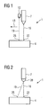
- FIG. 1 shows a device 1, which has a welding device 7, in particular a laser 7, which is required for welding a component 4.
- This can be, in particular, a re-welding or a build-up welding (by powder, wire feed, or the like).
- the device 1 can be used in a connection of two workpieces to a component.
- the point to be welded on the component 4 is marked 22.
- the device 1 preferably has an additional second laser 10 for preheating the substrate 4, which irradiates by means of a separate laser beam 19 a point 25 which is different from the point 22 and which is welded immediately thereafter, when the laser 7 in a traversing 13th moves.
- the point 25 is preheated, but not on or melted.
- the point 25 is thus located starting from the point 22 in the direction of travel 13.
- the second laser 10 preferably has a lower laser power than the laser 7.
- the second laser 10 is attached directly to the welding device 7, preferably to the first laser 7.
- the welding device 7 preferably to the first laser 7.
- Other possibilities are conceivable.
- FIG. 2 shows a further embodiment possibility of the device.
- the laser 7 can simultaneously emit two laser beams through a device (not shown in detail) 28 or successively direct laser beams to the point to be welded 22 and the preheated point 25.
- the laser 7 is preferably designed so that the laser power is adjusted according to the surface to be irradiated 22, 25, ie, when the second laser beam 19 hits the point 25, the laser beam 19 has a lower power or the irradiation time is shorter to achieve a lower power for the local preheating of the substrate 4.
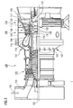
- FIG. 3 shows by way of example a gas turbine 100 in a longitudinal partial section.
- the gas turbine 100 has inside a rotatably mounted about a rotation axis 102 rotor 103 with a shaft 101, which is also referred to as a turbine runner.
- an intake housing 104 a compressor 105, for example, a toroidal combustion chamber 110, in particular annular combustion chamber, with a plurality of coaxially arranged burners 107, a turbine 108 and the exhaust housing 109th
- a compressor 105 for example, a toroidal combustion chamber 110, in particular annular combustion chamber, with a plurality of coaxially arranged burners 107, a turbine 108 and the exhaust housing 109th
- the annular combustion chamber 110 communicates with an annular annular hot gas channel 111, for example.
- annular annular hot gas channel 111 for example.
- turbine stages 112 connected in series form the turbine 108.
- Each turbine stage 112 is formed, for example, from two blade rings. As seen in the direction of flow of a working medium 113, in the hot gas channel 111 of a row of guide vanes 115, a series 125 formed of rotor blades 120 follows.
- the guide vanes 130 are fastened to an inner housing 138 of a stator 143, whereas the moving blades 120 of a row 125 are attached to the rotor 103 by means of a turbine disk 133, for example.
- air 105 is sucked in and compressed by the compressor 105 through the intake housing 104.
- the compressed air provided at the turbine-side end of the compressor 105 is supplied to the burners 107 where it is mixed with a fuel.
- the mixture is then burned to form the working fluid 113 in the combustion chamber 110.
- the working medium 113 flows along the hot gas channel 111 past the guide vanes 130 and the rotor blades 120.
- the working medium 113 relaxes on the rotor blades 120 in a pulse-transmitting manner, so that the blades 120 drive the rotor 103 and drive the machine coupled to it.
- the components exposed to the hot working medium 113 are subject to thermal loads during operation of the gas turbine 100.
- the guide vanes 130 and rotor blades 120 of the first turbine stage 112, viewed in the flow direction of the working medium 113, are subjected to the greatest thermal stress in addition to the heat shield elements lining the annular combustion chamber 110.
- substrates of the components may have a directional structure, i. they are monocrystalline (SX structure) or have only longitudinal grains (DS structure).
- iron-, nickel- or cobalt-based superalloys are used as the material for the components, in particular for the turbine blade 120, 130 and components of the combustion chamber 110.
- Such superalloys are for example from EP 1 204 776 B1 .
- EP 1 306 454 .
- the blades 120, 130 may be anti-corrosion coatings (MCrAlX; M is at least one element of the group iron (Fe), cobalt (Co), nickel (Ni), X is an active element and represents yttrium (Y) and / or silicon , Scandium (Sc) and / or at least one element of the rare earth or hafnium).
- M is at least one element of the group iron (Fe), cobalt (Co), nickel (Ni)
- X is an active element and represents yttrium (Y) and / or silicon , Scandium (Sc) and / or at least one element of the rare earth or hafnium).
- Such alloys are known from the EP 0 486 489 B1 .
- EP 0 412 397 B1 or EP 1 306 454 A1 are known from the EP 0 486 489 B1 .
- MCrAlX may still be present a thermal barrier coating, and consists for example of ZrO 2 , Y 2 O 3 -ZrO 2 , ie it is not, partially or completely stabilized by yttria and / or calcium oxide and / or magnesium oxide.
- the vane 130 has a guide vane foot (not shown here) facing the inner casing 138 of the turbine 108 and a vane head opposite the vane root.
- the vane head faces the rotor 103 and fixed to a mounting ring 140 of the stator 143.
- FIG. 4 shows a perspective view of a blade 120 or guide vane 130 of a turbomachine, which extends along a longitudinal axis 121.
- the turbomachine may be a gas turbine of an aircraft or a power plant for power generation, a steam turbine or a compressor.
- the blade 120, 130 has along the longitudinal axis 121 consecutively a fastening region 400, a blade platform 403 adjacent thereto and an airfoil 406 and a blade tip 415.
- the blade 130 may have at its blade tip 415 another platform (not shown).
- a blade root 183 is formed, which serves for attachment of the blades 120, 130 to a shaft or a disc (not shown).
- the blade root 183 is designed, for example, as a hammer head. Other designs as Christmas tree or Schwalbenschwanzfuß are possible.
- the blade 120, 130 has a leading edge 409 and a trailing edge 412 for a medium flowing past the airfoil 406.
- Such superalloys are for example from EP 1 204 776 B1 .
- EP 1 306 454 .
- the blade 120, 130 can be made by a casting process, also by directional solidification, by a forging process, by a milling process or combinations thereof.
- Workpieces with a monocrystalline structure or structures are used as components for machines which are exposed to high mechanical, thermal and / or chemical stresses during operation.
- Such monocrystalline workpieces takes place e.g. by directed solidification from the melt.
- These are casting processes in which the liquid metallic alloy is transformed into a monocrystalline structure, i. to the single-crystal workpiece, or directionally solidified.
- dendritic crystals are aligned along the heat flow and form either a columnar grain structure (columnar, i.e., grains that run the full length of the workpiece and here, in common usage, are referred to as directionally solidified) or a monocrystalline structure, i. the whole workpiece consists of a single crystal.
- a columnar grain structure columnar, i.e., grains that run the full length of the workpiece and here, in common usage, are referred to as directionally solidified
- a monocrystalline structure i. the whole workpiece consists of a single crystal.
- directionally solidified microstructures which means both single crystals that have no grain boundaries or at most small angle grain boundaries, and stem crystal structures that have probably longitudinal grain boundaries but no transverse grain boundaries.
- stem crystal structures that have probably longitudinal grain boundaries but no transverse grain boundaries.
- second-mentioned crystalline Structures are also called directionally solidified structures.
- the blades 120, 130 may have coatings against corrosion or oxidation, e.g. M is at least one element of the group iron (Fe), cobalt (Co), nickel (Ni), X is an active element and stands for yttrium (Y) and / or silicon and / or at least one element of the rare ones Earth, or hafnium (Hf)).
- M is at least one element of the group iron (Fe), cobalt (Co), nickel (Ni)
- X is an active element and stands for yttrium (Y) and / or silicon and / or at least one element of the rare ones Earth, or hafnium (Hf)).
- Such alloys are known from the EP 0 486 489 B1 .
- EP 0 412 397 B1 or EP 1 306 454 A1 are known from the EP 0 486 489 B1 .
- the density is preferably 95% of the theoretical density.
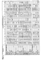
- the layer composition comprises Co-30Ni-28Cr-8Al-0.6Y-0.7Si or Co-28Ni-24Cr-10Al-0.6Y.
- nickel-based protective layers such as Ni-10Cr-12Al-0.6Y-3Re or Ni-12Co-21Cr-11Al-0.4Y-2Re or Ni-25Co-17Cr-10Al-0.4Y-1 are also preferably used , 5RE.
- thermal barrier coating which is preferably the outermost layer, and consists for example of ZrO 2 , Y 2 O 3 -ZrO 2 , ie it is not, partially or completely stabilized by yttria and / or calcium oxide and / or magnesium oxide.
- the thermal barrier coating covers the entire MCrAlX layer.
- suitable coating methods e.g. Electron beam evaporation (EB-PVD) produces stalk-shaped grains in the thermal barrier coating.
- the thermal barrier coating may be porous, micro- or macro-cracked grains have better thermal shock resistance.
- the thermal barrier coating is therefore preferably more porous than the MCrAlX layer.
- Refurbishment means that components 120, 130 may need to be deprotected after use (e.g., by sandblasting). This is followed by removal of the corrosion and / or oxidation layers or products. Optionally, even cracks in the component 120, 130 are repaired. This is followed by a re-coating of the component 120, 130 and a renewed use of the component 120, 130.
- the blade 120, 130 may be hollow or solid. If the blade 120, 130 is to be cooled, it is hollow and may still film cooling holes 418 (indicated by dashed lines) on.
Landscapes
- Physics & Mathematics (AREA)
- Optics & Photonics (AREA)
- Engineering & Computer Science (AREA)
- Mechanical Engineering (AREA)
- Plasma & Fusion (AREA)
- Turbine Rotor Nozzle Sealing (AREA)
Priority Applications (1)
| Application Number | Priority Date | Filing Date | Title |
|---|---|---|---|
| EP08019755A EP2186594A1 (fr) | 2008-11-12 | 2008-11-12 | Procédé et dispositif de préchauffage lors du soudage utilisant un deuxième faisceau laser |
Applications Claiming Priority (1)
| Application Number | Priority Date | Filing Date | Title |
|---|---|---|---|
| EP08019755A EP2186594A1 (fr) | 2008-11-12 | 2008-11-12 | Procédé et dispositif de préchauffage lors du soudage utilisant un deuxième faisceau laser |
Publications (1)
| Publication Number | Publication Date |
|---|---|
| EP2186594A1 true EP2186594A1 (fr) | 2010-05-19 |
Family
ID=40512241
Family Applications (1)
| Application Number | Title | Priority Date | Filing Date |
|---|---|---|---|
| EP08019755A Withdrawn EP2186594A1 (fr) | 2008-11-12 | 2008-11-12 | Procédé et dispositif de préchauffage lors du soudage utilisant un deuxième faisceau laser |
Country Status (1)
| Country | Link |
|---|---|
| EP (1) | EP2186594A1 (fr) |
Cited By (8)
| Publication number | Priority date | Publication date | Assignee | Title |
|---|---|---|---|---|
| EP2774712A1 (fr) * | 2013-03-07 | 2014-09-10 | Siemens Aktiengesellschaft | Procédé laser avec des plages de rayonnement laser différentes au sein d'un rayon |
| EP2774713A1 (fr) * | 2013-03-07 | 2014-09-10 | Siemens Aktiengesellschaft | Procédé laser avec des plages de rayonnement laser différentes au sein d'un rayon et dispositifs |
| DE102013223957A1 (de) * | 2013-11-22 | 2015-05-28 | Siemens Aktiengesellschaft | Auftragsschweißverfahren und Vorrichtung mit stangenförmigem Schweißzusatz-Werkstoff |
| US20150360320A1 (en) * | 2014-06-16 | 2015-12-17 | Toyota Jidosha Kabushiki Kaisha | Laser welding apparatus and laser welding method |
| DE102015207279A1 (de) * | 2015-04-22 | 2016-10-27 | Ipg Laser Gmbh | Fügevorrichtung und Fügeverfahren |
| DE102016218938A1 (de) * | 2016-09-29 | 2018-04-12 | Volkswagen Aktiengesellschaft | Fügeeinrichtung und Fügeverfahren |
| WO2019151912A1 (fr) * | 2018-02-01 | 2019-08-08 | Stjernberg Automation Ab | Procédés et systèmes de revêtement d'une surface |
| CN115673549A (zh) * | 2022-11-24 | 2023-02-03 | 哈尔滨工业大学 | 一种玻璃-金属激光复合焊接方法 |
Citations (18)
| Publication number | Priority date | Publication date | Assignee | Title |
|---|---|---|---|---|
| JPS54153745A (en) * | 1978-05-24 | 1979-12-04 | Nec Corp | Method and apparatus for laser processing |
| JPS60121093A (ja) * | 1983-12-06 | 1985-06-28 | Mitsubishi Heavy Ind Ltd | レ−ザ溶接方法 |
| JPH01143784A (ja) * | 1987-11-30 | 1989-06-06 | Mitsubishi Heavy Ind Ltd | 異軸多焦点式レーザビーム集光装置 |
| JPH0332481A (ja) * | 1989-06-29 | 1991-02-13 | Komatsu Ltd | レーザ肉盛溶接装置 |
| EP0486489B1 (fr) | 1989-08-10 | 1994-11-02 | Siemens Aktiengesellschaft | Revetement anticorrosion resistant aux temperatures elevees, notamment pour elements de turbines a gaz |
| EP0412397B1 (fr) | 1989-08-10 | 1998-03-25 | Siemens Aktiengesellschaft | Revêtement protecteur contenant du rhénium possédant une résistance plus grande à la corrosion et l'oxydation |
| EP0892090A1 (fr) | 1997-02-24 | 1999-01-20 | Sulzer Innotec Ag | Procédé de fabrication de structure smonocristallines |
| EP0786017B1 (fr) | 1994-10-14 | 1999-03-24 | Siemens Aktiengesellschaft | Couche de protection de pieces contre la corrosion, l'oxydation et les contraintes thermiques excessives, et son procede de production |
| WO1999067435A1 (fr) | 1998-06-23 | 1999-12-29 | Siemens Aktiengesellschaft | Alliage a solidification directionnelle a resistance transversale a la rupture amelioree |
| US6024792A (en) | 1997-02-24 | 2000-02-15 | Sulzer Innotec Ag | Method for producing monocrystalline structures |
| WO2000044949A1 (fr) | 1999-01-28 | 2000-08-03 | Siemens Aktiengesellschaft | Superalliage a base de nickel presentant une bonne usinabilite |
| US6191379B1 (en) * | 1999-04-05 | 2001-02-20 | General Electric Company | Heat treatment for weld beads |
| US6269540B1 (en) * | 1998-10-05 | 2001-08-07 | National Research Council Of Canada | Process for manufacturing or repairing turbine engine or compressor components |
| EP1306454A1 (fr) | 2001-10-24 | 2003-05-02 | Siemens Aktiengesellschaft | Revêtement protecteur contenant du rhénium pour la protection d'un élément contre l'oxydation et la corrosion aux températures élevées |
| EP1319729A1 (fr) | 2001-12-13 | 2003-06-18 | Siemens Aktiengesellschaft | Pièce résistante à des températures élevées réalisé en superalliage polycristallin ou monocristallin à base de nickel |
| EP1204776B1 (fr) | 1999-07-29 | 2004-06-02 | Siemens Aktiengesellschaft | Piece resistant a des temperatures elevees et son procede de production |
| US20050194363A1 (en) * | 2004-03-04 | 2005-09-08 | Yiping Hu | Multi-laser beam welding high strength superalloys |
| CA2215940C (fr) * | 1996-09-23 | 2006-06-13 | National Research Council Of Canada | Appareil de frittage laser pour fabriquer des revetements et des pieces metalliques denses |
-
2008
- 2008-11-12 EP EP08019755A patent/EP2186594A1/fr not_active Withdrawn
Patent Citations (18)
| Publication number | Priority date | Publication date | Assignee | Title |
|---|---|---|---|---|
| JPS54153745A (en) * | 1978-05-24 | 1979-12-04 | Nec Corp | Method and apparatus for laser processing |
| JPS60121093A (ja) * | 1983-12-06 | 1985-06-28 | Mitsubishi Heavy Ind Ltd | レ−ザ溶接方法 |
| JPH01143784A (ja) * | 1987-11-30 | 1989-06-06 | Mitsubishi Heavy Ind Ltd | 異軸多焦点式レーザビーム集光装置 |
| JPH0332481A (ja) * | 1989-06-29 | 1991-02-13 | Komatsu Ltd | レーザ肉盛溶接装置 |
| EP0486489B1 (fr) | 1989-08-10 | 1994-11-02 | Siemens Aktiengesellschaft | Revetement anticorrosion resistant aux temperatures elevees, notamment pour elements de turbines a gaz |
| EP0412397B1 (fr) | 1989-08-10 | 1998-03-25 | Siemens Aktiengesellschaft | Revêtement protecteur contenant du rhénium possédant une résistance plus grande à la corrosion et l'oxydation |
| EP0786017B1 (fr) | 1994-10-14 | 1999-03-24 | Siemens Aktiengesellschaft | Couche de protection de pieces contre la corrosion, l'oxydation et les contraintes thermiques excessives, et son procede de production |
| CA2215940C (fr) * | 1996-09-23 | 2006-06-13 | National Research Council Of Canada | Appareil de frittage laser pour fabriquer des revetements et des pieces metalliques denses |
| EP0892090A1 (fr) | 1997-02-24 | 1999-01-20 | Sulzer Innotec Ag | Procédé de fabrication de structure smonocristallines |
| US6024792A (en) | 1997-02-24 | 2000-02-15 | Sulzer Innotec Ag | Method for producing monocrystalline structures |
| WO1999067435A1 (fr) | 1998-06-23 | 1999-12-29 | Siemens Aktiengesellschaft | Alliage a solidification directionnelle a resistance transversale a la rupture amelioree |
| US6269540B1 (en) * | 1998-10-05 | 2001-08-07 | National Research Council Of Canada | Process for manufacturing or repairing turbine engine or compressor components |
| WO2000044949A1 (fr) | 1999-01-28 | 2000-08-03 | Siemens Aktiengesellschaft | Superalliage a base de nickel presentant une bonne usinabilite |
| US6191379B1 (en) * | 1999-04-05 | 2001-02-20 | General Electric Company | Heat treatment for weld beads |
| EP1204776B1 (fr) | 1999-07-29 | 2004-06-02 | Siemens Aktiengesellschaft | Piece resistant a des temperatures elevees et son procede de production |
| EP1306454A1 (fr) | 2001-10-24 | 2003-05-02 | Siemens Aktiengesellschaft | Revêtement protecteur contenant du rhénium pour la protection d'un élément contre l'oxydation et la corrosion aux températures élevées |
| EP1319729A1 (fr) | 2001-12-13 | 2003-06-18 | Siemens Aktiengesellschaft | Pièce résistante à des températures élevées réalisé en superalliage polycristallin ou monocristallin à base de nickel |
| US20050194363A1 (en) * | 2004-03-04 | 2005-09-08 | Yiping Hu | Multi-laser beam welding high strength superalloys |
Cited By (15)
| Publication number | Priority date | Publication date | Assignee | Title |
|---|---|---|---|---|
| US10144092B2 (en) | 2013-03-07 | 2018-12-04 | Siemens Aktiengesellschaft | Laser method with different laser beam areas within a beam |
| EP2774713A1 (fr) * | 2013-03-07 | 2014-09-10 | Siemens Aktiengesellschaft | Procédé laser avec des plages de rayonnement laser différentes au sein d'un rayon et dispositifs |
| WO2014135362A1 (fr) * | 2013-03-07 | 2014-09-12 | Siemens Aktiengesellschaft | Procédé laser à différentes zones de faisceau laser au sein d'un faisceau |
| WO2014135358A1 (fr) * | 2013-03-07 | 2014-09-12 | Siemens Aktiengesellschaft | Procédé laser présentant diverses zones de faisceau laser au sein d'un faisceau et dispositifs |
| EP2774712A1 (fr) * | 2013-03-07 | 2014-09-10 | Siemens Aktiengesellschaft | Procédé laser avec des plages de rayonnement laser différentes au sein d'un rayon |
| US9884391B2 (en) | 2013-03-07 | 2018-02-06 | Siemens Aktiengesellschaft | Laser method with different laser beam areas within a beam and devices |
| DE102013223957A1 (de) * | 2013-11-22 | 2015-05-28 | Siemens Aktiengesellschaft | Auftragsschweißverfahren und Vorrichtung mit stangenförmigem Schweißzusatz-Werkstoff |
| US20150360320A1 (en) * | 2014-06-16 | 2015-12-17 | Toyota Jidosha Kabushiki Kaisha | Laser welding apparatus and laser welding method |
| US9802272B2 (en) * | 2014-06-16 | 2017-10-31 | Toyota Jidosha Kabushiki Kaisha | Laser welding apparatus and laser welding method |
| DE102015207279A1 (de) * | 2015-04-22 | 2016-10-27 | Ipg Laser Gmbh | Fügevorrichtung und Fügeverfahren |
| US10894300B2 (en) | 2015-04-22 | 2021-01-19 | Ipg Laser Gmbh | Laser-based joining of components |
| DE102016218938A1 (de) * | 2016-09-29 | 2018-04-12 | Volkswagen Aktiengesellschaft | Fügeeinrichtung und Fügeverfahren |
| WO2019151912A1 (fr) * | 2018-02-01 | 2019-08-08 | Stjernberg Automation Ab | Procédés et systèmes de revêtement d'une surface |
| CN115673549A (zh) * | 2022-11-24 | 2023-02-03 | 哈尔滨工业大学 | 一种玻璃-金属激光复合焊接方法 |
| CN115673549B (zh) * | 2022-11-24 | 2025-02-28 | 哈尔滨工业大学 | 一种玻璃-金属激光复合焊接方法 |
Similar Documents
| Publication | Publication Date | Title |
|---|---|---|
| EP2117758B1 (fr) | Réparation par soudage de défauts intérieurs | |
| EP2414127B1 (fr) | Methode de soudage d'un evidement dans un composant par le depot de cordons de soudure a l'exterieur ou autour du contour ; composant correspondant | |
| EP2450471A1 (fr) | Procédé d'application de matériaux et de réparation d'un composant un composant | |
| DE102008018264A1 (de) | Schweißverfahren mit geregeltem Temperaturverlauf und eine Vorrichtung dafür | |
| EP1952931A1 (fr) | Mechtrode ayant une alimentation en poudre et procédé d'utilisation de cette mechtrode | |
| EP2330230A1 (fr) | Matériel de masquage, couche de masquage, procédé de masquage d'un substrat et procédé de revêtement d'un substrat | |
| EP2100687A1 (fr) | Chauffage de fil en acier sans potentiel lors de la soudure et son dispositif | |
| EP2369131A1 (fr) | Réparation de bords d'un composant à l'aide de bandes PSP et composant | |
| EP2312267A1 (fr) | Procédé de mesure de l'épaisseur de couche par triangulation laser et dispositif | |
| EP2254726A2 (fr) | Élément à soudures superposées et procédé de production correspondant | |
| DE102008019636A1 (de) | Bauteil mit Schweißnaht und Verfahren zur Herstellung einer Schweißnaht | |
| EP2062672A1 (fr) | Méthode de brasage de fissures larges | |
| EP2226149A1 (fr) | Procédé de soudure en deux étapes | |
| EP2224039A1 (fr) | Revêtement doté d'un procédé de revêtement thermique et non thermique | |
| EP2078578A1 (fr) | Soudage de trous, procédé de revêtement de tiges de soudage | |
| EP2583784A1 (fr) | Préparation d'au moins un poste à souder avant le soudage et composant | |
| EP2088224A1 (fr) | Procédé de fabrication d'une couche rugueuse et système de couche | |
| EP2584067A1 (fr) | Composant avec graphène et procédé de fabrication de composants avec graphène | |
| EP2312122A1 (fr) | Détermination d'une référence pour l'établissement de la position de trous bouchés, dispositif et dispositif d'usinage | |
| EP2138258A1 (fr) | Procédé de soudage à profil de température à plusieurs niveaux | |
| EP2460608A1 (fr) | Fabrication d'un fil d'acier à l'aide du procédé de prototypage rapide, fil d'acier et procédé de soudage | |
| EP2558245B1 (fr) | Lot contenant du germanium, un composant doté d'un lot et un procédé de soudage | |
| EP2053145A1 (fr) | Procédé d'enlèvement d'une couche métallique à l'aide de FIC dans une étape intermédiaire | |
| DE102008015913A1 (de) | Vorrichtung zum Schweißen mit einer Prozesskammer und ein Schweißverfahren | |
| WO2018114766A1 (fr) | Procédé d'assemblage de segments de composants à gaz chaud par brasage et composant à gaz chaud correspondant |
Legal Events
| Date | Code | Title | Description |
|---|---|---|---|
| PUAI | Public reference made under article 153(3) epc to a published international application that has entered the european phase |
Free format text: ORIGINAL CODE: 0009012 |
|
| AK | Designated contracting states |
Kind code of ref document: A1 Designated state(s): AT BE BG CH CY CZ DE DK EE ES FI FR GB GR HR HU IE IS IT LI LT LU LV MC MT NL NO PL PT RO SE SI SK TR |
|
| AX | Request for extension of the european patent |
Extension state: AL BA MK RS |
|
| AKY | No designation fees paid | ||
| STAA | Information on the status of an ep patent application or granted ep patent |
Free format text: STATUS: THE APPLICATION IS DEEMED TO BE WITHDRAWN |
|
| 18D | Application deemed to be withdrawn |
Effective date: 20101120 |
|
| REG | Reference to a national code |
Ref country code: DE Ref legal event code: R108 Effective date: 20110510 |