EP2186661A1 - Veränderbare Abstützung einer Schraubendruckfeder oder dergleichen für ein Kraftfahrzeug - Google Patents
Veränderbare Abstützung einer Schraubendruckfeder oder dergleichen für ein Kraftfahrzeug Download PDFInfo
- Publication number
- EP2186661A1 EP2186661A1 EP09012782A EP09012782A EP2186661A1 EP 2186661 A1 EP2186661 A1 EP 2186661A1 EP 09012782 A EP09012782 A EP 09012782A EP 09012782 A EP09012782 A EP 09012782A EP 2186661 A1 EP2186661 A1 EP 2186661A1
- Authority
- EP
- European Patent Office
- Prior art keywords
- spring
- support according
- changeable support
- helical compression
- pad
- Prior art date
- Legal status (The legal status is an assumption and is not a legal conclusion. Google has not performed a legal analysis and makes no representation as to the accuracy of the status listed.)
- Granted
Links
Images


Classifications
-
- B—PERFORMING OPERATIONS; TRANSPORTING
- B60—VEHICLES IN GENERAL
- B60G—VEHICLE SUSPENSION ARRANGEMENTS
- B60G11/00—Resilient suspensions characterised by arrangement, location or kind of springs
- B60G11/14—Resilient suspensions characterised by arrangement, location or kind of springs having helical, spiral or coil springs only
- B60G11/16—Resilient suspensions characterised by arrangement, location or kind of springs having helical, spiral or coil springs only characterised by means specially adapted for attaching the spring to axle or sprung part of the vehicle
-
- B—PERFORMING OPERATIONS; TRANSPORTING
- B60—VEHICLES IN GENERAL
- B60G—VEHICLE SUSPENSION ARRANGEMENTS
- B60G11/00—Resilient suspensions characterised by arrangement, location or kind of springs
- B60G11/26—Resilient suspensions characterised by arrangement, location or kind of springs having fluid springs only, e.g. hydropneumatic springs
- B60G11/28—Resilient suspensions characterised by arrangement, location or kind of springs having fluid springs only, e.g. hydropneumatic springs characterised by means specially adapted for attaching the spring to axle or sprung part of the vehicle
-
- B—PERFORMING OPERATIONS; TRANSPORTING
- B62—LAND VEHICLES FOR TRAVELLING OTHERWISE THAN ON RAILS
- B62D—MOTOR VEHICLES; TRAILERS
- B62D17/00—Means on vehicles for adjusting camber, castor, or toe-in
-
- F—MECHANICAL ENGINEERING; LIGHTING; HEATING; WEAPONS; BLASTING
- F16—ENGINEERING ELEMENTS AND UNITS; GENERAL MEASURES FOR PRODUCING AND MAINTAINING EFFECTIVE FUNCTIONING OF MACHINES OR INSTALLATIONS; THERMAL INSULATION IN GENERAL
- F16F—SPRINGS; SHOCK-ABSORBERS; MEANS FOR DAMPING VIBRATION
- F16F1/00—Springs
- F16F1/02—Springs made of steel or other material having low internal friction; Wound, torsion, leaf, cup, ring or the like springs, the material of the spring not being relevant
- F16F1/04—Wound springs
- F16F1/12—Attachments or mountings
- F16F1/121—Attachments or mountings adjustable, e.g. to modify spring characteristics
-
- B—PERFORMING OPERATIONS; TRANSPORTING
- B60—VEHICLES IN GENERAL
- B60G—VEHICLE SUSPENSION ARRANGEMENTS
- B60G2202/00—Indexing codes relating to the type of spring, damper or actuator
- B60G2202/10—Type of spring
- B60G2202/12—Wound spring
-
- B—PERFORMING OPERATIONS; TRANSPORTING
- B60—VEHICLES IN GENERAL
- B60G—VEHICLE SUSPENSION ARRANGEMENTS
- B60G2204/00—Indexing codes related to suspensions per se or to auxiliary parts
- B60G2204/10—Mounting of suspension elements
- B60G2204/12—Mounting of springs or dampers
- B60G2204/124—Mounting of coil springs
-
- B—PERFORMING OPERATIONS; TRANSPORTING
- B60—VEHICLES IN GENERAL
- B60G—VEHICLE SUSPENSION ARRANGEMENTS
- B60G2204/00—Indexing codes related to suspensions per se or to auxiliary parts
- B60G2204/40—Auxiliary suspension parts; Adjustment of suspensions
- B60G2204/43—Fittings, brackets or knuckles
-
- B—PERFORMING OPERATIONS; TRANSPORTING
- B60—VEHICLES IN GENERAL
- B60G—VEHICLE SUSPENSION ARRANGEMENTS
- B60G2204/00—Indexing codes related to suspensions per se or to auxiliary parts
- B60G2204/40—Auxiliary suspension parts; Adjustment of suspensions
- B60G2204/44—Centering or positioning means
- B60G2204/4402—Spacers or shims
-
- B—PERFORMING OPERATIONS; TRANSPORTING
- B60—VEHICLES IN GENERAL
- B60G—VEHICLE SUSPENSION ARRANGEMENTS
- B60G2204/00—Indexing codes related to suspensions per se or to auxiliary parts
- B60G2204/61—Adjustable during maintenance
-
- B—PERFORMING OPERATIONS; TRANSPORTING
- B60—VEHICLES IN GENERAL
- B60G—VEHICLE SUSPENSION ARRANGEMENTS
- B60G2206/00—Indexing codes related to the manufacturing of suspensions: constructional features, the materials used, procedures or tools
- B60G2206/01—Constructional features of suspension elements, e.g. arms, dampers, springs
- B60G2206/70—Materials used in suspensions
- B60G2206/73—Rubber; Elastomers
-
- B—PERFORMING OPERATIONS; TRANSPORTING
- B60—VEHICLES IN GENERAL
- B60G—VEHICLE SUSPENSION ARRANGEMENTS
- B60G2206/00—Indexing codes related to the manufacturing of suspensions: constructional features, the materials used, procedures or tools
- B60G2206/01—Constructional features of suspension elements, e.g. arms, dampers, springs
- B60G2206/80—Manufacturing procedures
- B60G2206/82—Joining
- B60G2206/8209—Joining by deformation
-
- B—PERFORMING OPERATIONS; TRANSPORTING
- B60—VEHICLES IN GENERAL
- B60G—VEHICLE SUSPENSION ARRANGEMENTS
- B60G2206/00—Indexing codes related to the manufacturing of suspensions: constructional features, the materials used, procedures or tools
- B60G2206/01—Constructional features of suspension elements, e.g. arms, dampers, springs
- B60G2206/90—Maintenance
- B60G2206/91—Assembly procedures
Definitions
- the invention relates to a variable support of a helical compression spring or the like for a motor vehicle according to the preamble of claim 1 and 10.
- bobenend horrin be used as suspension springs in motor vehicles for cushioning. They consist of a spring wire, which are wound with a constant or variable pitch in the entire effective range and with a constant or variable winding diameter about a coil spring axis. In this case, at least one spring end and / or both spring ends is supported on spring pads.
- the DE 199 39 515 C2 describes a strut for a motor vehicle, in which a support member made of a plastic and in addition an elastic pad made of a rubber material are used on a lower spring plate.
- the support element and the base are closed annularly.
- a strut with adjustable support of a helical compression spring discloses the DE 100 54 488 A1 , The helical compression spring shown there is supported on one end of the piston rod on a spring plate and on the other hand on a spring plate connected to the housing of a vibration damper. Such a spring plate is pivotally mounted in a support member and has one of the respective end turns of the helical compression spring adapted spring support.
- the DE 10 2008 004 089 A1 discloses a coil spring for a chassis of motor vehicles, which includes an adjusting device.
- a MacPherson automotive strut can be removed which is constructed so that the piston rod can be mounted off-center at one end.
- An essential feature of loaded helical compression springs is the eccentric application of force via the end surfaces in the spring body, and a shear stress of the spring body caused by the axial kinematics caused shear movement of the spring supports each other. This load results in additional stresses.
- increasing power density in vehicle construction has made it increasingly difficult to set higher standards for individual machine elements. New concepts are needed to meet these power densities.
- helical compression springs or the like components that are very heavily loaded. In such a load, they experience very complex stresses, which are due to each other in the geometric shape of the spring wire whose winding and in the shear behavior of the spring pad. Especially in a component assembly with other rigid components, the helical compression springs as elastic components significantly influence the system behavior.
- the present invention seeks to provide a helical compression spring or the like for motor vehicles with a spring pad that allows a variable spring position with identical axle components and body-side spring mounts.
- the mechanical stresses of the helical compression springs are determined in their load, in particular by the introduction of force over the effective surface pairs. As pairs of effective surfaces, the end turns of the helical compression spring are considered. This circumstance can result in an off-center load application, which in turn results in lateral forces and moments being generated in the end regions. These additional stresses generated reduce the life of such a spring.
- the introduced into the spring shear forces and moments can be reduced.
- the eccentric bearings constructed in accordance with the present invention are formed separately.
- the spring pad is designed so that it has for holding the helical compression spring or the like in alignment with the center line of the spring receiver and also the helical compression spring aligned spring holder.
- the connection to the body or the chassis is realized by a mounting approach, which is formed in an eccentric to the aforementioned center line. So it is possible that an eccentricity can be created by means of a rigid spring pad.
- the eccentricity can vary depending on the vehicle type.
- the mounting approach is stabilized against rotation by a Arretmaschinesanthesis so that it can not rotate about its own axis. With such an eccentrically designed mounting approach, it is possible to take different positions, for example, within the body.
- the spring pad preferably has a hard core surrounded by a sheath which is preferably made of an elastomer or the like.
- Mounting pins and locking pins are preferably equipped with a tip so that they can be mounted faster in the assembly process.
- the assembly approach and the locking pin form a positive connection to prevent rotation of the spring pad and can be formed with a circular cross-section.
- the mounting projection preferably has projections on its outer circumference, so that during assembly within the bodywork panel the mounting approach virtually engages with the bodywork.
- the rotation can in addition to form-fitting also have other designs, eg. B. adhesion and / or material bond, which are also included in the patent application.
- the spring pad can be extended by an essay or the like in their vertical extent.
- the mounting lug may not have a circular cross-section but is parallel through two Surfaces that merge into half cylinders at their ends, formed.
- Such a configuration of a form fit to prevent rotation is suitable that at least in an elaborated as a slot breakthrough within the body, a predetermined position can be taken. While this may be a limitation over the first preferred embodiment, this is a matter of design of the vehicle.
- Another advantage is in particular that no increase in the number of axle components and body parts is necessary. By this measure, a simple determination of the optimal spring position for maximum life of such a coil spring is given. At the same time, however, a tuning potential of chassis characteristics is possible by offsetting the force action line of the helical compression spring.
- axle concepts such as air spring / steel spring or torsion-beam axles / multi-link axles or different load groups in a series with the same body-side spring mounts is thus possible.
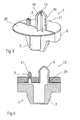
- FIG. 1 A first preferred embodiment of a spring pad 1 is in FIG. 1 shown.
- the core is adjoined by a plate 24, to which an eccentric dimension A is offset, a mounting attachment center line 9 is indicated.
- a mounting attachment centerline 9 around a mounting lug 4 is provided, which is intended for use on a body 2 or suspension. So that the mounting lug 4 also finds a firm anchoring within the body 2, projections 10 are formed on its circumference.
- a locking lug 5 is present, which ensures that when inserted spring pad 1 within the body 2 no distortion can take place here. It is thus a form fit to prevent rotation.
- FIG. 2 An installation situation of such a spring pad 1 is the FIG. 2 again.
- a bore 23 is introduced for the mounting lug 4 within the body 2.
- 2 holes 22 are present within the body. Within these holes 22 of the locking projection 5 dives, so that the spring pad 1 can not rotate.
- the basic structure of the first preferred embodiment of the spring pad 1 can in the perspective view in cut form and the FIG. 3 be taken again.
- the core 7 is preferably made of a harder material than, for example, the sheath 6 and the support surface 21, which rests against the body 2.
- the sheath 6 is preferably made of an elastomer or the like.
- the attachment 13 is designed so that it has an opening for the mounting lug 4 and preferably a blind hole for the Arretianssanthesis 5.
- the mounting lug 4 and the locking lug 5 equipped with tips 11.
- a mounting projection 16 is shown, which is arranged on a spring pad 20, for example for an air spring 15.
- the execution of the mounting projection 16 can be applied in the same way for the spring pad 1.
- the mounting projection 16 has two parallel outer surfaces, which are brought together in semicircles 18 at the ends. One of the semicircles 18 lies with its center on the center line 8 of the spring pad 20.
- Such a mounting lug 16 is suitable for being used in a position rotated by 180 ° within the body 2.
- FIG. 6 shows the FIG. 6 in which a breakthrough 17 has been shown as a slot for the mounting lug 16.
- the body 2 has at the edge of the opening 17 on a flange 12, which is so dimensionally coordinated that the mounting boss 16 is inserted during insertion firmly within the opening 17.
Landscapes
- Engineering & Computer Science (AREA)
- Mechanical Engineering (AREA)
- General Engineering & Computer Science (AREA)
- Chemical & Material Sciences (AREA)
- Combustion & Propulsion (AREA)
- Transportation (AREA)
- Springs (AREA)
- Vehicle Body Suspensions (AREA)
Abstract
Description
- Die Erfindung betrifft eine veränderbare Abstützung einer Schraubendruckfeder oder dergleichen für ein Kraftfahrzeug gemäß dem Oberbegriff des Patentanspruches 1 und 10.
- Schraubenddruckfedern werden als Tragfedern bei Kraftfahrzeugen zur Abfederung eingesetzt. Sie bestehen dabei aus einem Federdraht, der mit gleich bleibender oder variabler Steigung im gesamten federungswirksamen Bereich und mit gleich bleibendem oder variablem Windungsdurchmesser um eine Schraubenfedermittelachse gewickelt sind. Dabei ist zumindest ein Federende und/oder beide Federenden an Federunterlagen abgestützt.
- Die
DE 199 39 515 C2 beschreibt ein Federbein für ein Kraftfahrzeug, bei dem auf einem unteren Federteller ein Stützelement aus einem Kunststoff und zusätzlich eine elastische Unterlage aus einem Gummimaterial verwendet werden. Das Stützelement und die Unterlage sind dabei ringförmig geschlossen. - Ein Federbein mit einstellbarer Abstützung einer Schraubendruckfeder offenbart die
DE 100 54 488 A1 . Die dort dargestellte Schraubendruckfeder stützt sich an einem Ende der Kolbenstange an einem Federteller und andererseits an einem mit dem Gehäuse eines Schwingungsdämpfers verbundenen Federteller ab. Ein solcher Federteller ist schwenkbar in einem Abstützteil angeordnet und weist eine der jeweiligen Endwindungen der Schraubendruckfeder angepasste Federauflage auf. - Die
DE 10 2008 004 089 A1 offenbart eine Schraubenfeder für ein Fahrwerk von Kraftfahrzeugen, die eine Einstellvorrichtung beinhaltet. - Aus der
US 4 946 188 kann ein MacPherson-Federbein für Automobile entnommen werden, das so aufgebaut ist, dass die Kolbenstange an einem Ende außermittig montiert werden kann. - Ein wesentliches Merkmal von belasteten Schraubendruckfedern ist die exzentrische Krafteinleitung über die Endflächen in den Federkörper, sowie eine Scherbelastung des Federkörpers hervorgerufen durch die aus der Achskinematik bedingte Scherbewegung der Federauflagen zueinander. Aus dieser Belastung resultieren zusätzliche Beanspruchungen. Zudem ist eine steigende Leistungsdichte im Fahrzeugbau dazu angetan, immer höhere Ansprüche an die einzelnen Maschinenelemente zu stellen. Dabei sind neue Konzepte erforderlich, um diese Leistungsdichten zu erfüllen.
- In der Kraftfahrzeugindustrie sind Schraubendruckfedern oder dergleichen Bauteile, die sehr hoch belastet sind. Bei einer solchen Belastung erfahren sie sehr komplexe Beanspruchungen, die in der geometrischen Form des Federdrahtes,dessen Wicklung als auch in dem Scherverhalten der Federunterlage zueinander begründet sind. Gerade in einem Bauteilverbund mit anderen starren Komponenten beeinflussen die Schraubendruckfedern als elastische Komponenten das Systemverhalten maßgeblich.
- Ausgehend von dem vorliegenden Stand der Technik liegt der Erfindung die Aufgabe zugrunde, eine Schraubendruckfeder oder dergleichen für Kraftfahrzeuge mit einer Federunterlage bereitzustellen, die eine variable Federposition bei identischen Achsbauteilen und karosserieseitigen Federaufnahmen gestattet.
- Gelöst wird die Aufgabe jeweils durch die Merkmale der Ansprüche 1 und 10.
- Die Unteransprüche geben eine weitere Ausgestaltung des erfindungsgemäßen Gegenstandes wieder.
- Die mechanischen Beanspruchungen der Schraubendruckfedern werden in ihrer Belastung, insbesondere durch die Krafteinleitung über die Wirkflächenpaare bestimmt. Als Wirkflächenpaare werden die Endwindungen der Schraubendruckfeder angesehen. Durch diesen Umstand kann daraus ein außermittiger Lastangriff resultieren, was wieder zur Folge hat, dass in den Endbereichen Querkräfte und Momente erzeugt werden. Diese erzeugten zusätzlichen Spannungen reduzieren die Lebensdauer einer solchen Feder.
- Durch die Erfindung, nämlich durch eine auf die Federverformung abgestimmte Umgebungskonstruktion, können die in die Feder eingebrachten Querkräfte und Momente reduziert werden.
- So ist es möglich, dass bei einer Scherung des Federkörpers durch die Achskinematik die auftretenden Beanspruchungen gesenkt werden können. Entsprechende Abweichungen von der mittleren Beanspruchung hin zu größeren Werten, kann als zusätzliche Spannung bezeichnet werden. Gerade durch diese zusätzlichen Spannungen wird eine Reduzierung der Lebensdauer der Schraubendruckfeder hervorgerufen.
- Die gemäß der vorliegenden Erfindung ausgeführten Exzenterlager sind getrennt ausgebildet. Dabei ist die Federunterlage so gestaltet, dass sie zur Halterung der Schraubendruckfeder oder dergleichen eine fluchtend zu der Mittellinie der Federaufnahme und auch der Schraubendruckfeder ausgerichtete Federhalterung aufweist. Die Verbindung jedoch zur Karosserie oder zum Fahrwerk hin wird durch einen Montageansatz realisiert, der in einem Exzentermaß zu der vor genannter Mittellinie ausgebildet ist. So ist es möglich, dass eine Exzentrizität mittels einer starren Federunterlage geschaffen werden kann. Das Exzentrizitätsmaß kann dabei je nach Fahrzeugtyp variieren. Der Montageansatz wird gegen Verdrehen durch einen Arretierungsansatz so stabilisiert, dass dieser sich nicht um seine eigene Achse drehen kann. Mit einem derartig exzentrisch ausgebildeten Montageansatz ist es möglich, unterschiedliche Positionen beispielsweise innerhalb der Karosserie einzunehmen.
- Die Federunterlage hat vorzugsweise einen harten Kern, der von einer Umhüllung umgeben ist, der vorzugsweise aus einem Elastomer oder dergleichen besteht. Montagezapfen und Arretierungszapfen sind vorzugsweise mit einer Spitze ausgerüstet, damit sie in dem Montageprozess schneller montiert werden können.
- Der Montageansatz und der Arretierungszapfen bilden einen Formschluss zur Verdrehsicherung für die Federunterlage und können dabei mit einem kreisrunden Querschnitt ausgebildet sein. Der Montageansatz weist dabei vorzugsweise an seinem äußeren Umfang noch Vorsprünge auf, damit bei der Montage innerhalb des Karosseriebleches der Montageansatz sich quasi mit der Karosserie verkrallt. Die Verdrehsicherung kann neben Formschluss auch andere Gestaltungen aufweisen, z. B. Kraftschluss und/oder Stoffschluss, die vom Patentbegehren ebenfalls mit umfasst sind.
- Um eine derartige Federunterlage auch für unterschiedliche Fahrzeugderivate verwenden zu können, ist es möglich, dass die Federunterlage durch einen Aufsatz oder dergleichen in ihrer Höhenerstreckung verlängert werden kann.
- In einer zweiten bevorzugten Ausführungsform kann der Montageansatz nicht einen kreisrunden Querschnitt aufweisen sondern ist durch zwei parallele Flächen, die an ihren Enden jeweils in halbe Zylinder übergehen, ausgebildet. Eine derartige Ausgestaltung eines Formschlusses zur Verdrehsicherung ist dazu geeignet, dass zumindest in einem als Langloch ausgearbeiteten Durchbruch innerhalb der Karosserie eine vorbestimmt ausgerichtete Position eingenommen werden kann. Dieses mag zwar gegenüber der ersten bevorzugten Ausführungsform eine Einschränkung sein, jedoch ist dies eine Frage der Konstruktion des Fahrzeuges.
- Ein weiterer Vorteil besteht insbesondere darin, dass keine Variantenerhöhung von Achsbauteilen und Karosserieteilen notwendig ist. Durch diese Maßnahme ist eine einfache Festlegung der optimalen Federposition für eine maximale Lebensdauer einer derartigen Schraubenfeder gegeben. Gleichzeitig ist jedoch ein Abstimmpotenzial von Fahrwerkseigenschaften durch ein Versetzen der Kraftwirkungslinie der Schraubendruckfeder möglich.
- Auch die Verbaumöglichkeit unterschiedlicher Achskonzepte, wie zum Beispiel Luftfeder/Stahlfeder oder Verbundlenkerachsen/Mehrlenkerachsen oder unterschiedliche Lastgruppen in einer Baureihe bei gleichen karosserieseitigen Federaufnahmen ist somit möglich.
- Weitere Vorteile, Merkmale und Anwendungsmöglichkeiten der Erfindung ergeben sich aus der nachfolgenden Beschreibung in Verbindung mit dem in den Zeichnungen dargestellten Ausführungsbeispiel.
- Die Erfindung wird im Folgenden anhand des in der Zeichnung dargestellten Ausführungsbeispiels näher beschrieben. In der Beschreibung, in den Patentansprüchen, der Zusammenfassung und in der Zeichnung werden die in der hinten angeführten Liste der Bezugszeichen verwendeten Begriffe und zugeordneten Bezugszeichen verwendet. Es zeigen:
- Fig. 1
- Eine erste bevorzugte Ausführungsform einer Federunterlage in einer Schnittdarstellung mit einer zentrischen Federauf- nahme und dazu exzentrisch angeordnetem Montageansatz;
- Fig. 2
- eine Einbausituation der Federunterlage gemäß
Figur 1 ; - Fig. 3
- eine perspektivische Darstellung der Federunterlage gemäß
Figur 1 ; - Fig. 4
- eine Schnittdarstellung der Federunterlage gemäß
Figur 1 mit einem Aufsatz; - Fig. 5
- eine zweite bevorzugte Ausführungsform einer Federunterla- ge mit angeschlossener Luftfeder;
- Fig. 6
- die Ausführung eines Durchbruches innerhalb einer Karosse- rie für die Federunterlage gemäß
Figur 5 . - Eine erste bevorzugte Ausführungsform einer Federunterlage 1 wird in
Figur 1 dargestellt. In der Schnittdarstellung platziert sich um eine Mittellinie 8 ein Kern 7, der von einer Umhüllung als Federaufnahme 3 umgeben ist. Mit dieser Federaufnahme 3 wird die Verbindung zu der nicht dargestellten Schraubendruckfeder oder dergleichen hergestellt. An den Kern schließt sich ein Teller 24 an, an dem, um ein Exentermaß A versetzt, eine Montageansatzmittellinie 9 ausgewiesen ist. Um die Montageansatzmittellinie 9 herum ist ein Montageansatz 4 ausgebildet, der zur Verwendung an einer Karosserie 2 oder Radaufhängung vorgesehen ist. Damit der Montageansatz 4 auch innerhalb der Karosserie 2 eine feste Verankerung findet, sind auf seinem Umfang Vorsprünge 10 ausgebildet. Neben dem Montageansatz 4 ist auch noch ein Arretierungsansatz 5 vorhanden, der dafür sorgt, dass bei eingesetzter Federunterlage 1 innerhalb der Karosserie 2 hier keine Verdrehung stattfinden kann. Es handelt sich somit um einen Formschluss zur Verdrehsicherung. - Eine Einbausituation einer derartigen Federunterlage 1 gibt die
Figur 2 wieder. Dabei ist innerhalb der Karosserie 2 eine Bohrung 23 für den Montageansatz 4 eingebracht. Um eine hiervon unterschiedliche Position, beispielsweise um 180° verdreht, für den Montageansatz 4 und damit direkt für die Federunterlage 1 zu erreichen, sind innerhalb der Karosserie 2 Bohrungen 22 vorhanden. Innerhalb dieser Bohrungen 22 taucht der Arretierungsansatz 5 ein, so dass die Federunterlage 1 sich nicht mehr verdrehen kann. - Aufgrund der konstruktiven Gegebenheiten eines Fahrzeuges ist es möglich, dass neben den zwei gegenüberliegend angeordneten Bohrungen 22 der
Figur 2 weitere Bohrungen auf einem Kreisdurchmesser angelegt werden, um so unterschiedliche Einbaupositionen für die Federunterlage zu schaffen. - Den grundsätzlichen Aufbau der ersten bevorzugten Ausführungsform der Federunterlage 1 kann in der perspektivischen Darstellung in geschnittener Form auch der
Figur 3 noch einmal entnommen werden. Der Kern 7 ist dabei vorzugsweise aus einem härteren Material als beispielsweise die Umhüllung 6 und die Auflagefläche 21, die sich gegen die Karosserie 2 anlegt. Die Umhüllung 6 ist vorzugsweise aus einem Elastomer oder dergleichen. - Um gleiche Federunterlagen 1 auch bei unterschiedlichen Fahrzeugen verwenden zu können, können diese mit einem Aufsatz 13 in der Höhe verändert werden. Dabei ist der Aufsatz 13 so gestaltet, dass er einen Durchbruch für den Montageansatz 4 und vorzugsweise eine Sackbohrung für den Arretierungsansatz 5 aufweist. Zur besseren Montage sind sowohl der Montageansatz 4 als auch der Arretierungsansatz 5 mit Spitzen 11 ausgestattet.
- In der
Figur 5 wird in einer zweiten bevorzugten Ausführungsform ein Montageansatz 16 wiedergegeben, der an einer Federunterlage 20, beispielsweise für eine Luftfeder 15, angeordnet ist. Prinzipiell kann die Ausführung des Montageansatzes 16 in gleicher Weise auch für die Federunterlage 1 angewendet werden. Dabei weist der Montageansatz 16 zwei parallele äußere Flächen auf, die an den Enden in Halbkreisen 18 zusammengeführt werden. Einer der Halbkreise 18 liegt mit seinem Mittelpunkt auf der Mittellinie 8 der Federunterlage 20. Ein derartiger Montageansatz 16 eignet sich dafür, um in einer Position um 180° verdreht innerhalb der Karosserie 2 eingesetzt zu werden. Dieses zeigt dieFigur 6 , bei der ein Durchbruch 17 als Langloch für den Montageansatz 16 dargestellt worden ist. Die Karosserie 2 weist am Rand des Durchbruches 17 eine Bördelung 12 auf, die so maßlich abgestimmt ist, dass der Montageansatz 16 beim Einführen fest innerhalb des Durchbruches 17 eintaucht. -
- 1
- Federunterlage
- 2
- Karosserie
- 3
- Federaufnahme
- 4
- Montageansatz
- 5
- Arretierungsansatz
- 6
- Umhüllung
- 7
- Kern
- 8
- Mittellinie
- 9
- Montageansatzmittellinie
- 10
- Vorsprünge
- 11
- Spitze
- 12
- Bördelung
- 13
- Aufsatz
- 14
- Verstärkungsrippen
- 15
- Luftfeder
- 16
- Montageansatz
- 17
- Durchbruch
- 18
- Halbkreis
- 19
- parallele Flächen
- 20
- Federunterlage
- 21
- Auflagefläche
- 22
- Bohrung
- 23
- Bohrung
- 24
- Teller
- 25
- Durchbruch
- A
- Exzentermaß
Claims (15)
- Veränderbare Abstützung einer Schraubendruckfeder oder dergleichen für ein Kraftfahrzeug, deren erstes Federende sich an einer Karosserie (2) oder einem Achsbauteil und deren zweites Federende sich an einer Radaufhängung abstützt, wobei zumindest ein Federende über eine Federunterlage (1) an der Karosserie (2), dem Achsbauteil oder der Radaufhängung anliegt, dadurch gekennzeichnet, dass die Federunterlage (1) zur Halterung der Schraubendruckfeder oder dergleichen eine fluchtend zu einer Mittellinie (8) angeordnete Federaufnahme (3) und einem dazu in einem Exzentermaß (A) versetzt ausgebildeten Montageansatz (4) aufweist.
- Veränderbare Abstützung nach Anspruch 1, dadurch gekennzeichnet, dass das Exzentermaß (A) je nach Fahrzeugtyp variabel ist.
- Veränderbare Abstützung nach Anspruch 1, dadurch gekennzeichnet, dass die Federunterlage (1) eine Verdrehsicherung aufweist.
- Veränderbare Abstützung nach Anspruch 3, dadurch gekennzeichnet, dass die Verdrehsicherung über Formschluss und/oder Kraftschluss und/oder Stoffschluss gebildet ist.
- Veränderbare Abstützung nach Anspruch 4, dadurch gekennzeichnet, dass zur Verdrehsicherung mittels Formschluss neben dem Montageansatz (4) ein Arretierungsansatz (5) angeordnet ist.
- Veränderbare Abstützung nach einem der vorhergehenden Ansprüche, dadurch gekennzeichnet, dass der Montageaufsatz (4) einen kreisrunden Querschnitt aufweist.
- Veränderbare Abstützung nach einem der vorhergehenden Ansprüche, dadurch gekennzeichnet, dass auf dem äußeren Umfang des Montageansatzes (4) Vorsprünge (10) angeordnet sind.
- Veränderbare Abstützung nach einem der vorhergehenden Ansprüche, dadurch gekennzeichnet, dass die Federunterlage (1) mit einem Aufsatz (13) in ihrer Höhenerstreckung verlängerbar ist.
- Veränderbare Abstützung nach einem der vorhergehenden Ansprüche, dadurch gekennzeichnet, dass die Karosserie (2), das Achsbauteil und/oder die Radaufhängung zur Aufnahme der Federunterlage (1) eine dem Montageansatz (4) entsprechende Bohrung (23) und mindestens eine dem Arretierungsansatz (5) entsprechende Bohrung (22) aufweist.
- Veränderbare Abstützung einer Schraubendruckfeder oder dergleichen für ein Kraftfahrzeug, deren erstes Federende sich mit an einer Karosserie (2) oder einem Achsbauteil und deren zweites Federende sich an einer Radaufhängung abstützt, wobei zumindest ein Federende über eine Federunterlage (20) an der Karosserie (2), dem Achsbauteil oder der Radaufhängung anliegt, dadurch gekennzeichnet, dass die Federunterlage (20) einen Montageansatz (16) für eine Feder aufweist, der als Formschluss zur Verdrehsicherung ausgebildet ist.
- Veränderbare Abstützung nach Anspruch 9, dadurch gekennzeichnet, dass der Formschluss zur Verdrehsicherung durch zwei parallele Flächen (19) mit an deren Enden sich anschließenden halben Zylindern (18) aufweist, wobei einer der halben Zylinder (18) in der Mittelachse (8) der Federunterlage (20) liegt.
- Veränderbare Abstützung nach Anspruch 10 oder 11, dadurch gekennzeichnet, dass in der Karosserie (2) ein Durchbruch (17) in Form eines Montageansatzes (16) vorhanden ist.
- Veränderbare Abstützung nach einem der vorhergehenden Ansprüche, dadurch gekennzeichnet, dass die Federunterlage (1, 20) durch einen entsprechend gestalteten Formschluss und/oder Kraftschloss und/oder Stoffschluss frei ausrichtbar ist.
- Veränderbare Abstützung nach einem der vorhergehenden Ansprüche, dadurch gekennzeichnet, dass die Federunterlage (1) in unterschiedlichen Positionen montierbar ist.
- Kraftfahrzeug, dessen Federung mittels Schraubendruckfedern oder dergleichen realisiert ist, die mit Federunterlagen (1, 20) gemäß den vorhergehenden Ansprüchen ausgestattet sind.
Applications Claiming Priority (1)
| Application Number | Priority Date | Filing Date | Title |
|---|---|---|---|
| DE102008057325A DE102008057325A1 (de) | 2008-11-14 | 2008-11-14 | Veränderbare Abstützung einer Schraubendruckfeder oder dergleichen |
Publications (2)
| Publication Number | Publication Date |
|---|---|
| EP2186661A1 true EP2186661A1 (de) | 2010-05-19 |
| EP2186661B1 EP2186661B1 (de) | 2013-03-20 |
Family
ID=41622453
Family Applications (1)
| Application Number | Title | Priority Date | Filing Date |
|---|---|---|---|
| EP20090012782 Not-in-force EP2186661B1 (de) | 2008-11-14 | 2009-10-09 | Veränderbare Abstützung einer Schraubendruckfeder oder dergleichen für ein Kraftfahrzeug |
Country Status (2)
| Country | Link |
|---|---|
| EP (1) | EP2186661B1 (de) |
| DE (1) | DE102008057325A1 (de) |
Cited By (2)
| Publication number | Priority date | Publication date | Assignee | Title |
|---|---|---|---|---|
| EP2466167A3 (de) * | 2010-12-18 | 2017-02-22 | Audi AG | Federunterlage für eine freistehende Tragfeder eines Kraftfahrzeugs |
| CN114834200A (zh) * | 2022-05-09 | 2022-08-02 | 岚图汽车科技有限公司 | 一种偏心分体式弹簧支承结构及悬架结构 |
Families Citing this family (4)
| Publication number | Priority date | Publication date | Assignee | Title |
|---|---|---|---|---|
| JP5293340B2 (ja) * | 2009-03-30 | 2013-09-18 | スズキ株式会社 | スプリングシート及びスプリングシートの取り付け構造 |
| DE102015221126B4 (de) | 2015-10-29 | 2025-02-27 | Ford Global Technologies, Llc | Federanordnung für ein Kraftfahrzeug |
| DE202015106077U1 (de) | 2015-10-29 | 2015-11-18 | Ford Global Technologies, Llc | Federanordnung für ein Kraftfahrzeug |
| DE102015221129A1 (de) | 2015-10-29 | 2017-05-04 | Ford Global Technologies, Llc | Federanordnung für ein Kraftfahrzeug |
Citations (10)
| Publication number | Priority date | Publication date | Assignee | Title |
|---|---|---|---|---|
| EP0092066A1 (de) * | 1982-04-21 | 1983-10-26 | FIAT AUTO S.p.A. | Fahrzeugradaufhängung |
| US4946188A (en) | 1989-10-12 | 1990-08-07 | Doreen Mason | Wheel alignment |
| DE4340556A1 (de) * | 1993-11-29 | 1995-06-01 | Porsche Ag | Radaufhängung |
| EP0985565A1 (de) * | 1998-09-14 | 2000-03-15 | Peugeot Citroen Automobiles SA | Obere Dämpferbefestigungsvorrichtung einer Kraftfahrzeugradaufhängung |
| DE10054488A1 (de) | 1999-12-21 | 2001-07-05 | Mannesmann Sachs Ag | Federbein mit einstellbarer Abstützung einer Schraubendruckfeder |
| US6382645B1 (en) * | 2000-12-04 | 2002-05-07 | Northstar Manufacturing Co., Inc. | Offset upper strut mount |
| DE19939515C2 (de) | 1999-08-20 | 2002-06-13 | Porsche Ag | Federbein für ein Kraftfahrzeug mit einer Lagerung für eine Schraubenfeder |
| EP1321319A1 (de) * | 2001-12-21 | 2003-06-25 | ContiTech Vibration Control GmbH | Federbeinstützlager |
| EP1743784A2 (de) * | 2005-07-12 | 2007-01-17 | Zf Friedrichshafen Ag | Federteller-Auflage |
| DE102008004089A1 (de) | 2007-01-30 | 2008-07-31 | Schaeffler Kg | Schraubenfeder für ein Fahrwerk |
Family Cites Families (2)
| Publication number | Priority date | Publication date | Assignee | Title |
|---|---|---|---|---|
| DE10005849A1 (de) * | 1999-02-23 | 2000-08-24 | Mannesmann Sachs Ag | Federteller-Auflage mit Geräuschreduzierung |
| US6149171A (en) * | 1999-03-31 | 2000-11-21 | Daimlerchrysler Corporation | Spring isolator for a motor vehicle suspension |
-
2008
- 2008-11-14 DE DE102008057325A patent/DE102008057325A1/de not_active Withdrawn
-
2009
- 2009-10-09 EP EP20090012782 patent/EP2186661B1/de not_active Not-in-force
Patent Citations (10)
| Publication number | Priority date | Publication date | Assignee | Title |
|---|---|---|---|---|
| EP0092066A1 (de) * | 1982-04-21 | 1983-10-26 | FIAT AUTO S.p.A. | Fahrzeugradaufhängung |
| US4946188A (en) | 1989-10-12 | 1990-08-07 | Doreen Mason | Wheel alignment |
| DE4340556A1 (de) * | 1993-11-29 | 1995-06-01 | Porsche Ag | Radaufhängung |
| EP0985565A1 (de) * | 1998-09-14 | 2000-03-15 | Peugeot Citroen Automobiles SA | Obere Dämpferbefestigungsvorrichtung einer Kraftfahrzeugradaufhängung |
| DE19939515C2 (de) | 1999-08-20 | 2002-06-13 | Porsche Ag | Federbein für ein Kraftfahrzeug mit einer Lagerung für eine Schraubenfeder |
| DE10054488A1 (de) | 1999-12-21 | 2001-07-05 | Mannesmann Sachs Ag | Federbein mit einstellbarer Abstützung einer Schraubendruckfeder |
| US6382645B1 (en) * | 2000-12-04 | 2002-05-07 | Northstar Manufacturing Co., Inc. | Offset upper strut mount |
| EP1321319A1 (de) * | 2001-12-21 | 2003-06-25 | ContiTech Vibration Control GmbH | Federbeinstützlager |
| EP1743784A2 (de) * | 2005-07-12 | 2007-01-17 | Zf Friedrichshafen Ag | Federteller-Auflage |
| DE102008004089A1 (de) | 2007-01-30 | 2008-07-31 | Schaeffler Kg | Schraubenfeder für ein Fahrwerk |
Cited By (2)
| Publication number | Priority date | Publication date | Assignee | Title |
|---|---|---|---|---|
| EP2466167A3 (de) * | 2010-12-18 | 2017-02-22 | Audi AG | Federunterlage für eine freistehende Tragfeder eines Kraftfahrzeugs |
| CN114834200A (zh) * | 2022-05-09 | 2022-08-02 | 岚图汽车科技有限公司 | 一种偏心分体式弹簧支承结构及悬架结构 |
Also Published As
| Publication number | Publication date |
|---|---|
| DE102008057325A8 (de) | 2010-09-02 |
| EP2186661B1 (de) | 2013-03-20 |
| DE102008057325A1 (de) | 2010-05-20 |
Similar Documents
| Publication | Publication Date | Title |
|---|---|---|
| EP2186661B1 (de) | Veränderbare Abstützung einer Schraubendruckfeder oder dergleichen für ein Kraftfahrzeug | |
| DE102009016139A1 (de) | Elastomergelenk | |
| DE112008000166T5 (de) | Gesteigerter Axialwert und verbesserte Haltbarkeit einer elastomeren Buchse | |
| DE10032222A1 (de) | Schwenklagerbuchse | |
| DE102015016142A1 (de) | Elastisches Lager zur Verbindung zweier Bauteile | |
| DE102014001943A1 (de) | Elastomer-Lagerbuchse, insbesondere zur Lagerung eines Stoßdämpfers einer Fahrzeug-Achsanbindung | |
| EP2906437A2 (de) | Befestigungsanordnung eines schwingungsdämpfers an einem radträger | |
| EP0137096B1 (de) | Elastische Lagerung von Blattfederenden für Strassen- und Schienenfahrzeuge | |
| DE102005003945B4 (de) | Buchsenlager mit in Umfangsrichtung wechselnder radialer Steifigkeit | |
| EP1691104B1 (de) | Elastisches Lager | |
| DE102017217598A1 (de) | Federbaugruppe | |
| DE102007016742A1 (de) | Gelenklager, insbesondere an einem Drehgelenk zwischen einem Vorderwagen und Hinterwagen eines Gelenkbusses | |
| DE102021118344A1 (de) | Gelenklager für die Abstützung eines Fahrzeug-Lenkerarms | |
| EP1124076A2 (de) | Gelenklager, insbesondere Stabilisatorlager für ein Fahrzeug | |
| DE102022104980A1 (de) | Lenkungsaktuator | |
| DE102015218944A1 (de) | Federauflage und Verfahren zu deren Herstellung | |
| DE102017201903A1 (de) | Lagereinheit, Lagerung und Fahrzeug | |
| DE20021481U1 (de) | Federwegbegrenzungselement | |
| DE102019200995A1 (de) | Anordnung zur Lagerung eines Aggregates in einem Kraftfahrzeug sowie Kraftfahrzeug mit einer derartigen Lagerungsanordnung | |
| DE102024114742B3 (de) | Starres Verbindungsteil zur mechanischen Kopplung eines ersten Bauteils und eines zweiten Bauteils | |
| DE10357080B4 (de) | Elastisches Federaugenlager zur Lagerung eines Federauges einer Blattfeder an einem Fahrzeug | |
| DE10357079B4 (de) | Elastische Federaugenlagerung zur Lagerung eines Federauges einer Blattfeder an einem Fahrzeug | |
| DE102017222821A1 (de) | Lagervorrichtung, Aggregatträgersystem und Kraftfahrzeug | |
| DE102007041647A1 (de) | Lagerbefestigung | |
| EP1571366B1 (de) | Elastisches Lager |
Legal Events
| Date | Code | Title | Description |
|---|---|---|---|
| PUAI | Public reference made under article 153(3) epc to a published international application that has entered the european phase |
Free format text: ORIGINAL CODE: 0009012 |
|
| AK | Designated contracting states |
Kind code of ref document: A1 Designated state(s): AT BE BG CH CY CZ DE DK EE ES FI FR GB GR HR HU IE IS IT LI LT LU LV MC MK MT NL NO PL PT RO SE SI SK SM TR |
|
| AX | Request for extension of the european patent |
Extension state: AL BA RS |
|
| RBV | Designated contracting states (corrected) |
Designated state(s): AT BE BG CH CY CZ DE DK EE ES FI FR GB GR HR HU IE IS IT LI LT LU LV MC MK MT NL NO PL PT RO SE SI SK SM TR |
|
| 17P | Request for examination filed |
Effective date: 20101119 |
|
| 17Q | First examination report despatched |
Effective date: 20110126 |
|
| GRAP | Despatch of communication of intention to grant a patent |
Free format text: ORIGINAL CODE: EPIDOSNIGR1 |
|
| RIC1 | Information provided on ipc code assigned before grant |
Ipc: B62D 17/00 20060101ALI20121112BHEP Ipc: B60G 17/02 20060101ALI20121112BHEP Ipc: B60G 11/28 20060101ALI20121112BHEP Ipc: F16F 1/12 20060101ALI20121112BHEP Ipc: B60G 11/16 20060101AFI20121112BHEP |
|
| GRAS | Grant fee paid |
Free format text: ORIGINAL CODE: EPIDOSNIGR3 |
|
| GRAA | (expected) grant |
Free format text: ORIGINAL CODE: 0009210 |
|
| AK | Designated contracting states |
Kind code of ref document: B1 Designated state(s): AT BE BG CH CY CZ DE DK EE ES FI FR GB GR HR HU IE IS IT LI LT LU LV MC MK MT NL NO PL PT RO SE SI SK SM TR |
|
| REG | Reference to a national code |
Ref country code: GB Ref legal event code: FG4D Free format text: NOT ENGLISH |
|
| REG | Reference to a national code |
Ref country code: CH Ref legal event code: EP |
|
| REG | Reference to a national code |
Ref country code: IE Ref legal event code: FG4D Free format text: LANGUAGE OF EP DOCUMENT: GERMAN |
|
| REG | Reference to a national code |
Ref country code: AT Ref legal event code: REF Ref document number: 601835 Country of ref document: AT Kind code of ref document: T Effective date: 20130415 |
|
| REG | Reference to a national code |
Ref country code: DE Ref legal event code: R096 Ref document number: 502009006530 Country of ref document: DE Effective date: 20130516 |
|
| PG25 | Lapsed in a contracting state [announced via postgrant information from national office to epo] |
Ref country code: SE Free format text: LAPSE BECAUSE OF FAILURE TO SUBMIT A TRANSLATION OF THE DESCRIPTION OR TO PAY THE FEE WITHIN THE PRESCRIBED TIME-LIMIT Effective date: 20130320 Ref country code: NO Free format text: LAPSE BECAUSE OF FAILURE TO SUBMIT A TRANSLATION OF THE DESCRIPTION OR TO PAY THE FEE WITHIN THE PRESCRIBED TIME-LIMIT Effective date: 20130620 Ref country code: LT Free format text: LAPSE BECAUSE OF FAILURE TO SUBMIT A TRANSLATION OF THE DESCRIPTION OR TO PAY THE FEE WITHIN THE PRESCRIBED TIME-LIMIT Effective date: 20130320 Ref country code: ES Free format text: LAPSE BECAUSE OF FAILURE TO SUBMIT A TRANSLATION OF THE DESCRIPTION OR TO PAY THE FEE WITHIN THE PRESCRIBED TIME-LIMIT Effective date: 20130701 Ref country code: BG Free format text: LAPSE BECAUSE OF FAILURE TO SUBMIT A TRANSLATION OF THE DESCRIPTION OR TO PAY THE FEE WITHIN THE PRESCRIBED TIME-LIMIT Effective date: 20130620 |
|
| REG | Reference to a national code |
Ref country code: LT Ref legal event code: MG4D |
|
| PG25 | Lapsed in a contracting state [announced via postgrant information from national office to epo] |
Ref country code: LV Free format text: LAPSE BECAUSE OF FAILURE TO SUBMIT A TRANSLATION OF THE DESCRIPTION OR TO PAY THE FEE WITHIN THE PRESCRIBED TIME-LIMIT Effective date: 20130320 Ref country code: SI Free format text: LAPSE BECAUSE OF FAILURE TO SUBMIT A TRANSLATION OF THE DESCRIPTION OR TO PAY THE FEE WITHIN THE PRESCRIBED TIME-LIMIT Effective date: 20130320 Ref country code: FI Free format text: LAPSE BECAUSE OF FAILURE TO SUBMIT A TRANSLATION OF THE DESCRIPTION OR TO PAY THE FEE WITHIN THE PRESCRIBED TIME-LIMIT Effective date: 20130320 Ref country code: GR Free format text: LAPSE BECAUSE OF FAILURE TO SUBMIT A TRANSLATION OF THE DESCRIPTION OR TO PAY THE FEE WITHIN THE PRESCRIBED TIME-LIMIT Effective date: 20130621 |
|
| REG | Reference to a national code |
Ref country code: NL Ref legal event code: VDEP Effective date: 20130320 |
|
| PG25 | Lapsed in a contracting state [announced via postgrant information from national office to epo] |
Ref country code: HR Free format text: LAPSE BECAUSE OF FAILURE TO SUBMIT A TRANSLATION OF THE DESCRIPTION OR TO PAY THE FEE WITHIN THE PRESCRIBED TIME-LIMIT Effective date: 20130320 |
|
| PG25 | Lapsed in a contracting state [announced via postgrant information from national office to epo] |
Ref country code: SK Free format text: LAPSE BECAUSE OF FAILURE TO SUBMIT A TRANSLATION OF THE DESCRIPTION OR TO PAY THE FEE WITHIN THE PRESCRIBED TIME-LIMIT Effective date: 20130320 Ref country code: NL Free format text: LAPSE BECAUSE OF FAILURE TO SUBMIT A TRANSLATION OF THE DESCRIPTION OR TO PAY THE FEE WITHIN THE PRESCRIBED TIME-LIMIT Effective date: 20130320 Ref country code: RO Free format text: LAPSE BECAUSE OF FAILURE TO SUBMIT A TRANSLATION OF THE DESCRIPTION OR TO PAY THE FEE WITHIN THE PRESCRIBED TIME-LIMIT Effective date: 20130320 Ref country code: CZ Free format text: LAPSE BECAUSE OF FAILURE TO SUBMIT A TRANSLATION OF THE DESCRIPTION OR TO PAY THE FEE WITHIN THE PRESCRIBED TIME-LIMIT Effective date: 20130320 Ref country code: PT Free format text: LAPSE BECAUSE OF FAILURE TO SUBMIT A TRANSLATION OF THE DESCRIPTION OR TO PAY THE FEE WITHIN THE PRESCRIBED TIME-LIMIT Effective date: 20130722 Ref country code: EE Free format text: LAPSE BECAUSE OF FAILURE TO SUBMIT A TRANSLATION OF THE DESCRIPTION OR TO PAY THE FEE WITHIN THE PRESCRIBED TIME-LIMIT Effective date: 20130320 Ref country code: IS Free format text: LAPSE BECAUSE OF FAILURE TO SUBMIT A TRANSLATION OF THE DESCRIPTION OR TO PAY THE FEE WITHIN THE PRESCRIBED TIME-LIMIT Effective date: 20130720 |
|
| PG25 | Lapsed in a contracting state [announced via postgrant information from national office to epo] |
Ref country code: PL Free format text: LAPSE BECAUSE OF FAILURE TO SUBMIT A TRANSLATION OF THE DESCRIPTION OR TO PAY THE FEE WITHIN THE PRESCRIBED TIME-LIMIT Effective date: 20130320 Ref country code: CY Free format text: LAPSE BECAUSE OF FAILURE TO SUBMIT A TRANSLATION OF THE DESCRIPTION OR TO PAY THE FEE WITHIN THE PRESCRIBED TIME-LIMIT Effective date: 20130320 |
|
| PLBE | No opposition filed within time limit |
Free format text: ORIGINAL CODE: 0009261 |
|
| STAA | Information on the status of an ep patent application or granted ep patent |
Free format text: STATUS: NO OPPOSITION FILED WITHIN TIME LIMIT |
|
| PG25 | Lapsed in a contracting state [announced via postgrant information from national office to epo] |
Ref country code: DK Free format text: LAPSE BECAUSE OF FAILURE TO SUBMIT A TRANSLATION OF THE DESCRIPTION OR TO PAY THE FEE WITHIN THE PRESCRIBED TIME-LIMIT Effective date: 20130320 |
|
| 26N | No opposition filed |
Effective date: 20140102 |
|
| REG | Reference to a national code |
Ref country code: DE Ref legal event code: R097 Ref document number: 502009006530 Country of ref document: DE Effective date: 20140102 |
|
| BERE | Be: lapsed |
Owner name: AUDI A.G. Effective date: 20131031 |
|
| PG25 | Lapsed in a contracting state [announced via postgrant information from national office to epo] |
Ref country code: MC Free format text: LAPSE BECAUSE OF FAILURE TO SUBMIT A TRANSLATION OF THE DESCRIPTION OR TO PAY THE FEE WITHIN THE PRESCRIBED TIME-LIMIT Effective date: 20130320 |
|
| REG | Reference to a national code |
Ref country code: CH Ref legal event code: PL |
|
| REG | Reference to a national code |
Ref country code: IE Ref legal event code: MM4A |
|
| PG25 | Lapsed in a contracting state [announced via postgrant information from national office to epo] |
Ref country code: LI Free format text: LAPSE BECAUSE OF NON-PAYMENT OF DUE FEES Effective date: 20131031 Ref country code: CH Free format text: LAPSE BECAUSE OF NON-PAYMENT OF DUE FEES Effective date: 20131031 |
|
| PG25 | Lapsed in a contracting state [announced via postgrant information from national office to epo] |
Ref country code: BE Free format text: LAPSE BECAUSE OF NON-PAYMENT OF DUE FEES Effective date: 20131031 |
|
| PG25 | Lapsed in a contracting state [announced via postgrant information from national office to epo] |
Ref country code: IE Free format text: LAPSE BECAUSE OF NON-PAYMENT OF DUE FEES Effective date: 20131009 |
|
| PG25 | Lapsed in a contracting state [announced via postgrant information from national office to epo] |
Ref country code: SM Free format text: LAPSE BECAUSE OF FAILURE TO SUBMIT A TRANSLATION OF THE DESCRIPTION OR TO PAY THE FEE WITHIN THE PRESCRIBED TIME-LIMIT Effective date: 20130320 |
|
| PG25 | Lapsed in a contracting state [announced via postgrant information from national office to epo] |
Ref country code: TR Free format text: LAPSE BECAUSE OF FAILURE TO SUBMIT A TRANSLATION OF THE DESCRIPTION OR TO PAY THE FEE WITHIN THE PRESCRIBED TIME-LIMIT Effective date: 20130320 |
|
| PG25 | Lapsed in a contracting state [announced via postgrant information from national office to epo] |
Ref country code: MK Free format text: LAPSE BECAUSE OF FAILURE TO SUBMIT A TRANSLATION OF THE DESCRIPTION OR TO PAY THE FEE WITHIN THE PRESCRIBED TIME-LIMIT Effective date: 20130320 Ref country code: HU Free format text: LAPSE BECAUSE OF FAILURE TO SUBMIT A TRANSLATION OF THE DESCRIPTION OR TO PAY THE FEE WITHIN THE PRESCRIBED TIME-LIMIT; INVALID AB INITIO Effective date: 20091009 Ref country code: LU Free format text: LAPSE BECAUSE OF NON-PAYMENT OF DUE FEES Effective date: 20131009 |
|
| PG25 | Lapsed in a contracting state [announced via postgrant information from national office to epo] |
Ref country code: MT Free format text: LAPSE BECAUSE OF FAILURE TO SUBMIT A TRANSLATION OF THE DESCRIPTION OR TO PAY THE FEE WITHIN THE PRESCRIBED TIME-LIMIT Effective date: 20130320 |
|
| REG | Reference to a national code |
Ref country code: FR Ref legal event code: PLFP Year of fee payment: 7 |
|
| REG | Reference to a national code |
Ref country code: AT Ref legal event code: MM01 Ref document number: 601835 Country of ref document: AT Kind code of ref document: T Effective date: 20141009 |
|
| PG25 | Lapsed in a contracting state [announced via postgrant information from national office to epo] |
Ref country code: AT Free format text: LAPSE BECAUSE OF NON-PAYMENT OF DUE FEES Effective date: 20141009 |
|
| REG | Reference to a national code |
Ref country code: FR Ref legal event code: PLFP Year of fee payment: 8 |
|
| REG | Reference to a national code |
Ref country code: FR Ref legal event code: PLFP Year of fee payment: 9 |
|
| REG | Reference to a national code |
Ref country code: FR Ref legal event code: PLFP Year of fee payment: 10 |
|
| P01 | Opt-out of the competence of the unified patent court (upc) registered |
Effective date: 20230530 |
|
| PGFP | Annual fee paid to national office [announced via postgrant information from national office to epo] |
Ref country code: GB Payment date: 20231023 Year of fee payment: 15 |
|
| PGFP | Annual fee paid to national office [announced via postgrant information from national office to epo] |
Ref country code: IT Payment date: 20231030 Year of fee payment: 15 Ref country code: FR Payment date: 20231024 Year of fee payment: 15 Ref country code: DE Payment date: 20231031 Year of fee payment: 15 |
|
| REG | Reference to a national code |
Ref country code: DE Ref legal event code: R119 Ref document number: 502009006530 Country of ref document: DE |
|
| GBPC | Gb: european patent ceased through non-payment of renewal fee |
Effective date: 20241009 |
|
| PG25 | Lapsed in a contracting state [announced via postgrant information from national office to epo] |
Ref country code: DE Free format text: LAPSE BECAUSE OF NON-PAYMENT OF DUE FEES Effective date: 20250501 |
|
| PG25 | Lapsed in a contracting state [announced via postgrant information from national office to epo] |
Ref country code: GB Free format text: LAPSE BECAUSE OF NON-PAYMENT OF DUE FEES Effective date: 20241009 |
|
| PG25 | Lapsed in a contracting state [announced via postgrant information from national office to epo] |
Ref country code: FR Free format text: LAPSE BECAUSE OF NON-PAYMENT OF DUE FEES Effective date: 20241031 |
|
| PG25 | Lapsed in a contracting state [announced via postgrant information from national office to epo] |
Ref country code: IT Free format text: LAPSE BECAUSE OF NON-PAYMENT OF DUE FEES Effective date: 20241009 |