EP2186958A2 - Elément d'isolation - Google Patents
Elément d'isolation Download PDFInfo
- Publication number
- EP2186958A2 EP2186958A2 EP09450218A EP09450218A EP2186958A2 EP 2186958 A2 EP2186958 A2 EP 2186958A2 EP 09450218 A EP09450218 A EP 09450218A EP 09450218 A EP09450218 A EP 09450218A EP 2186958 A2 EP2186958 A2 EP 2186958A2
- Authority
- EP
- European Patent Office
- Prior art keywords
- insulating
- wall
- elements
- insulating element
- channels
- Prior art date
- Legal status (The legal status is an assumption and is not a legal conclusion. Google has not performed a legal analysis and makes no representation as to the accuracy of the status listed.)
- Granted
Links
Images




Classifications
-
- E—FIXED CONSTRUCTIONS
- E04—BUILDING
- E04B—GENERAL BUILDING CONSTRUCTIONS; WALLS, e.g. PARTITIONS; ROOFS; FLOORS; CEILINGS; INSULATION OR OTHER PROTECTION OF BUILDINGS
- E04B1/00—Constructions in general; Structures which are not restricted either to walls, e.g. partitions, or floors or ceilings or roofs
- E04B1/62—Insulation or other protection; Elements or use of specified material therefor
- E04B1/74—Heat, sound or noise insulation, absorption, or reflection; Other building methods affording favourable thermal or acoustical conditions, e.g. accumulating of heat within walls
- E04B1/76—Heat, sound or noise insulation, absorption, or reflection; Other building methods affording favourable thermal or acoustical conditions, e.g. accumulating of heat within walls specifically with respect to heat only
- E04B1/78—Heat insulating elements
- E04B1/80—Heat insulating elements slab-shaped
-
- E—FIXED CONSTRUCTIONS
- E04—BUILDING
- E04B—GENERAL BUILDING CONSTRUCTIONS; WALLS, e.g. PARTITIONS; ROOFS; FLOORS; CEILINGS; INSULATION OR OTHER PROTECTION OF BUILDINGS
- E04B1/00—Constructions in general; Structures which are not restricted either to walls, e.g. partitions, or floors or ceilings or roofs
- E04B1/62—Insulation or other protection; Elements or use of specified material therefor
- E04B1/74—Heat, sound or noise insulation, absorption, or reflection; Other building methods affording favourable thermal or acoustical conditions, e.g. accumulating of heat within walls
- E04B1/76—Heat, sound or noise insulation, absorption, or reflection; Other building methods affording favourable thermal or acoustical conditions, e.g. accumulating of heat within walls specifically with respect to heat only
- E04B1/762—Exterior insulation of exterior walls
-
- E—FIXED CONSTRUCTIONS
- E04—BUILDING
- E04F—FINISHING WORK ON BUILDINGS, e.g. STAIRS, FLOORS
- E04F13/00—Coverings or linings, e.g. for walls or ceilings
- E04F13/007—Outer coverings for walls with ventilating means
-
- E—FIXED CONSTRUCTIONS
- E04—BUILDING
- E04F—FINISHING WORK ON BUILDINGS, e.g. STAIRS, FLOORS
- E04F13/00—Coverings or linings, e.g. for walls or ceilings
- E04F13/02—Coverings or linings, e.g. for walls or ceilings of plastic materials hardening after applying, e.g. plaster
- E04F13/04—Bases for plaster
Definitions
- the invention relates to a Dämman extract comprising a wall, such as an outer wall, and arranged on this wall continuous, closed insulating surface formed of a plurality of interconnected via their end faces insulating elements made of a foamed material or foam.
- the thermal insulation structure must be designed so that more moisture must be derived from the wall area, as replenished becomes.
- the moisture is dissipated by a lying between the wall and the insulation ventilation system.
- internal insulation construction thus provides a rule before abutting the inner wall slat construction, wherein the slats are spaced apart and form cavities for the rear ventilation.
- the insulation boards are then placed and attached to it. At the same time one can Thermal insulation and a rear ventilation or the removal of the water vapor-enriched air can be achieved.
- Various materials for insulation are also known from the prior art, for example mineral or organic fiber materials, organic or inorganic foams, porous materials in general and systems for vacuum thermal insulation, for example so-called vacuum insulation panels or vacuum insulation panels.
- the heat transport or the heat conduction essentially takes place through the mechanisms of heat conduction, thermal radiation and convection.
- the aim is to reduce these components in order to increase the insulating effect.
- the heat conduction through the solid can be reduced by using suitable materials or increased porosities and the heat radiation can be reduced by reflecting or absorbing elements.
- the convection or the heat conduction via the contained gas can be reduced very effectively by the provision of a vacuum.
- each Dämmelements or the Dämm configuration rear-ventilating means to allow venting or removal of water vapor from the area between the wall and the insulating surface, wherein between the insulating surface and the wall is provided a known condensate converter in the form of a layer of diffusion-open and / or hydrophilic plaster, which converts out of the wall condensation and / or wall moisture into water vapor and releases it as water vapor and which is suitable to absorb water from moistened masonry and To direct this water or the resulting water vapor through the plaster thickness and deliver it to the environment, so that the surface is always dry.
- a known condensate converter in the form of a layer of diffusion-open and / or hydrophilic plaster, which converts out of the wall condensation and / or wall moisture into water vapor and releases it as water vapor and which is suitable to absorb water from moistened masonry and To direct this water or the resulting water vapor through the plaster thickness and deliver it to the environment, so that the surface is always dry.
- Such Dämman shirt comes, as noted, without a separate ventilation structure, but the insulation elements are mounted directly on the wall or the special plaster.
- the Dämmanowski invention is thus very easy and quick to build.
- the wall to be insulated is damp or everywhere where high wall moisture prevails due to condensation or hygroscopy and insulation from the outside is not expedient, it is advantageous if between the insulating surface and the wall of the known condensate converter or a plaster layer is provided from diffusion-open hydrophilic plaster, which sucks in the emerging from the wall condensation and / or wall moisture and then converted into water vapor and releases. In this way, not only is it insulated, but at the same time the wall is effectively dehumidified.
- the condensate converter render and the back ventilation means interact in a particularly advantageous manner and complement each other synergistically.
- the combined use of the specially designed insulation elements and the condensate converter plaster can also be used to effectively insulate particularly delicate and damp walls.
- the insulating elements forming the insulating surface can be easily and easily transported, stored, mounted and loaded due to their low weight. Furthermore, such insulation elements can be very thin and space-saving due to the high thermal insulation values. Due to the direct arrangement of the rear ventilation means on the back or lower surface of each insulating element and the tedious and time-consuming construction of a separate ventilation structure can be omitted entirely. In addition, the entire insulation construction becomes thinner and more valuable space is gained, which is highly relevant in particular for interior insulation.
- the rear ventilation means are integrally formed or milled in the lower surface of each Dämmelements. In this way results in a very weight and space-saving design with full preservation of ventilation properties.
- each insulating element or the insulating surface is formed or milled into the lower surface of each insulating element or the insulating surface, each individual channel being open on both sides, and opening into different, preferably mutually opposite, side surfaces.
- the formation of easy-to-produce ventilation channels has the advantage that a well-defined way for the withdrawal of moist air is given and the moisture can be effectively sucked.
- the rear ventilation means or channels are each aligned with the rear ventilation means or channels of the respective adjacent insulating elements or fluidly connected, whereby on the underside of the insulating surface, a branched network is formed.
- each insulating element is solid or consists of foamed material through and through, as well as homogeneous and uniform. In this way, appropriate insulation elements can be produced and processed inexpensively. Also, the structural integrity and stability of such insulation ducks is relatively high.
- the insulating element is designed in the form of an envelope wall, which surrounds at least one evacuated, in particular in the fine vacuum range between 10 -3 and 1 mbar evacuated, cavity.
- an insulating element can thus be easily and easily transported, stored, mounted and loaded due to the low weight.
- such insulation elements can also be very thin and space-saving due to the high thermal insulation values.
- the cavity is substantially empty or free of an additional insulating material or a foamed fine-pored materials.
- an insulating element is lighter and by the vacuum even more effective than an insulating element filled with foam, since the heat conduction over the material of the foam matrix is eliminated.
- Advantageous negative pressures begin at about ⁇ 1 mbar.
- To reinforce may be provided in such a hollow insulating element that in the Hüllwandung, in particular on the underside opposite the inside, protruding into the cavity reinforcing ribs are formed or that the inside is curved or dome-shaped curved.
- the insulating element becomes stable and can also be used for use as a floor tile or for the insulation of floors in the basement area.
- This insulating element can advantageously be formed either in one piece or in one piece by blow molding or be composed of at least two partial elements. Depending on the material, this results in a favorable manufacturing process.
- this insulating element is gas-tight and evacuated, then it is more susceptible to damage, but cheaper to produce. If the insulating element has a valve, it can subsequently be ventilated or evacuated, whereby the flexibility is increased.
- each insulating element is one-piece or one-piece and recess-free. This also increases its stability, especially during storage and production and assembly. In addition, the production of such insulation elements is cheaper.
- each insulating element or the foamed material or the foam tight against the entrance, the passage and the diffusion of Liquids and gases, in particular of water and water vapor, or is absolutely impermeable to vapor and water.
- the foamed material or the foam of each insulating element is closed-cell, has no capillarity and / or water absorption. In this way, no water or moisture can accumulate or rise in the interior of the insulating element.
- each insulating element or the foamed material of Dämmelements is non-combustible, resistant to chemical influences, in particular acid-resistant and / or resistant to environmental influences, against insects and small animal feed.
- each insulating element is heat-insulating with a coefficient of thermal conductivity ⁇ ⁇ 0.06 W / K * m.
- a rigid foam or semi-rigid foam is used as the foam.
- the foam is a foam plastic, preferably polyurethane or polystyrene, for example XPS or EPS, or a foam concrete.
- foam glass which is very well suited even under extreme conditions due to its high pressure resistance, its virtually no water absorption and its vapor-tightness.
- Foam glass is highly heat-insulating, waterproof, pressure-resistant, vapor-tight, dimensionally stable, non-flammable, acid-resistant, pest-proof, easy to process and easy to recycle.
- each insulating element in particular at least one metallic foil or vapor-deposited coating.
- This serves to reduce the heat radiation and to increase the insulating effect.
- the films or coatings are preferably arranged on the lower surface of each Dämmelements, but may also be arranged in the cavity, preferably spaced from each other at both opposite inner surfaces of the cavity.
- the Insulation element via corresponding connecting means for example via a tongue and groove system or a step system for, preferably air and / or moisture-tight, connection with other similar insulating elements to form the flat closed insulating surface has, wherein the means are preferably integrally formed in the end faces ,
- each insulating element is plate-shaped, preferably substantially cuboidal, flat or curved, in particular with a maximum thickness of 5 cm, preferably about 1 to 3 cm, and / or that on the, the lower surface opposite surface of the Dämmelements a decorative layer od. Like. Applied is.
- Such insulation elements are easy stackable and storable and can also have aesthetic effects.
- each Dämmelements in particular on the projecting or raised surfaces of the rear ventilation means, plug means for mounting the Dämmelements are arranged on corresponding arranged in or on the wall receiving means.
- the receiving means may be a wall-mounted or partially recessed in the wall, cast in finished receiving grid, with which the plug-in means are brought into operative connection.
- the plug-in means may be formed as protruding nubs with an enlarged head, which are inserted into a corresponding fit against each other, molded into the wall recesses fit fit and positive fit.
- edges of the protruding or raised surfaces of the ventilating means are chamfered, whereby excessive and laterally bulging adhesive is buffered and the channels remain free.
- An advantageous condensate converter render is composed of sand, scrap glass and / or decontaminated household waste slag, cements and an additive containing surfactants and plastics, ground or crushed according to a specified grading curve.
- a particularly effective condensate converter has the following parameters: air pore content:> 35%, porosity:> 40% by volume, capillary water absorption:> 0.5 kg / m 2 , water penetration depth:> 5 mm, compressive strength: 1.5-5 N / mm 2 , vapor diffusion resistance: ⁇ ⁇ 12, grain size: 0 - 6 mm, preferably 0 - 2 mm, density: ⁇ 1.4 kg / dm 3 .
- a continuous, closed functional surface formed of a plurality of each other via their side surfaces, in particular air and / or moisture-proof, connected functional elements arranged, in particular glued, is.
- a functional surface provides additional heat and sound insulation.
- the individual functional elements are identical to the insulating elements with cavity, with the difference that the functional elements are filled with air or not evacuated.
- the provision of such non-evacuated functional elements also serves to protect the evacuated insulation panels. For example, nails or screws can be introduced into the functional elements, without affecting the functionality of the thermal insulation of the overall construction. In particular, this is required for vertical walls in the living area, where pictures or similar decorative elements are hung.
- Such a Dämman extract is advantageously arranged so that the functional surface or the individual functional elements with respect to the insulating surface is oriented such that the connecting lines or grooves between the individual elements of the respective surface are not superimposed, in particular offset from each other at maximum or in the plane are maximally laterally spaced from each other. In this way, the heat conduction is further reduced and the thermal bridges or the passage points of cool air are reduced or extended the ways.
- the insulating surface can, if desired and required with a functional coating e.g. be covered with a carpet, a wallpaper or a bitumen layer for the roof insulation.
- the channels remain permanently free and can ensure a gas or vapor exchange.
- a blockage by concrete, plaster od. Like. Should be avoided, otherwise their functionality of the rear ventilation would be impaired.
- edge strips or breathers made of a gas-permeable material and / or in the form of an exhaust duct are arranged on the side edges and / or inside the insulating surface, wherein the rear ventilation means or channels enter into these deaerators.
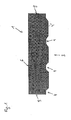
- Fig. 1 shows an insulating element 1 in cross section.
- the insulating element 1 is solid and consists through and out of foamed material or foam, which is homogeneously and uniformly distributed.
- foamed material or foam which is homogeneously and uniformly distributed.
- an insulating element. 1 to design integral foam, the density decreases continuously from the outside in and the insulating element 1 has a porous core and a nearly massive edge zone.
- the illustrated insulating element 1 is in one piece or in one piece and has no continuous recesses or blind holes.
- the insulating element 1 is substantially plate-shaped or cuboid, wherein the size may vary. As a rule, these are easy-to-handle tiles, plates, panels or bricks.
- the thickness of an insulating element 1 is in the range of about 1 to 3 cm with a maximum thickness of about 5 cm. In essence, the insulating element 1 is flat, but alternatively it can also be curved in order to adapt to a curvy course of the wall.
- insulating element 1 is made entirely of foam glass or glass foam.
- foams in particular hard foams, can be used.
- Polymer foams in particular thermosetting or thermoplastic foams, for example XPS or EPS, are also suitable.
- Glass foam panels are usually produced in a strand process, wherein the glass foam strand is cooled in a cooling system slowly and stress-free to room temperature. Glass foam panels are usually made entirely of recycled glass and can be recycled as well. They have a high compressive strength, whereby any compressive stresses can be absorbed almost without compression. In addition, they have a low density and are therefore lightweight and therefore very suitable for construction.
- the glass foam used is closed cell, i. The walls between the individual cells are completely closed, making the insulation boards 1 waterproof and also frost resistant.
- the insulating elements 1 have no capillarity.
- the insulating elements 1 of glass foam are chemically resistant, resistant to aging and also resistant to insects. In addition, they are not flammable and are classified in the building material class A1 and odorless.
- such insulating elements 1 made of glass foam are absolutely gas-tight and do not allow passage of gas.
- they have high thermal insulation properties with a thermal conductivity coefficient of about 0.03 - 0.06 W / K * m. These thermal insulation properties are also due to the negative pressure present in the cells, which can form during the cooling of the still hot material.
- the high vapor-tightness and the high watertightness make such insulation elements made of glass foam thus ideally suited for the present purpose.
- such insulating elements 1 are used made of glass foam without coating, but for better protection may also be provided special coatings or protective coatings.
- the insulating element 1 has a flat outer surface 6, which is usually facing the viewer and the underlying wall or wall 13 is turned away. On the opposite side of the insulating element 1 is the lower surface 3, which is facing in the assembly of the wall 13. On or in this lower surface 3 rear ventilation means 4 are provided, which enable and effect a ventilation or venting or removal of water vapor with correct installation.
- the back ventilation means 4 are integrally formed in the lower surface 3 by making the lower surface 3 profiled accordingly or by, e.g. by machining, the channels 4 are subsequently worked into the lower surface 3 or milled into it.
- edges of the protruding or raised surfaces 4 'of the rear ventilation means 4 and the channels 4 are chamfered, whereby a depot of excess adhesive is formed.
- Fig. 2 the insulation element 1 is shown from below.
- a grid-like, regular ventilation network of elevations 4 'and channels 4 is formed, in which a larger number of channels 4 intersect each other.
- the channels 4 are perpendicular to each other, whereby a corresponding regular pattern is drawn on the lower surface 3. Remain from the lower surface 3 projecting squares or rectangles 4 ', which are finally applied to the wall 13 or on a particular plaster or glued to it.
- the height of the channels 4 is usually not more than 5 mm, whereby no convection can take place in this area.
- the cross section of the channels 4 may be rectangular or curved. It is essential that the channels 4 remain permanently free and can ensure a gas or vapor exchange. A blockage by concrete, plaster od. Like. Should be avoided, otherwise their functionality of the rear ventilation would be eliminated.
- the rear ventilation system can be formed by other channel guides, for example by the formation of knobs or projections on the lower surface.
- the insulating element 1 in particular on the lower surface 3, not shown here, also means for reducing the heat radiation can be arranged.
- metallic foils and / or vapor-deposited metallic coatings are possible which can reflect and / or absorb the infrared radiation.
- connecting means 11 may be formed, which make it possible to assemble together a plurality of insulating elements 1 via corresponding connecting means 11 and connect to an insulating surface 15.
- interlocking tongue and groove systems can be formed, which ensure an actual mating and enable a floating construction or a composite.
- at least partially circumferential Jardinnfalze be provided which extend the gas passageway through the groove.
- the insulating element 1 according to Fig. 1 and 2 has however blunt edge surfaces. In any case, it is advantageous if the connecting means 11 are integrally and integrally formed in the insulating element 1, since this is easier to manufacture.
- FIG. 3 an insulation assembly according to the invention is shown, in which the individual insulating elements 1 are mounted on a wall 13 to be insulated.
- the individual insulating elements 1 form a continuous closed insulating surface 15, which is gas and moisture-proof.
- the insulating surface 15 is created from a plurality of composite in two dimensions with each other via their end faces 9 or touching contiguous insulating elements 1.
- the lower surfaces 3 of the insulating elements 1 with the ventilation means or channels 4 are the wall 13th turned.
- the protruding areas 4 ' form the direct contact with the wall 13 or with a plaster 25. In this way, a ventilation network 4, 4' for removing water vapor or moisture from this sensitive area between the wall 13 and the insulating surface 15 is formed.
- the moist air can escape via vent slots 27 or free edges.
- the channels 4 When installing the insulating elements 1, care must be taken that the channels 4 remain permanently free and continuous. They must not be blocked by glue or penetrating concrete or plaster. This also helps to prevent the chamfered edges of the channels 4.
- the individual insulating elements 1 of a Dämman extract be glued directly or directly to the wall 13 or mechanically fastened, the newly added Dämmimplantation 1 via the connecting means 11 as close as possible and tight or form-fitting to each other or to the side surfaces 9 of the already mounted Damping elements 1 are adjusted, with due consideration of the thermal expansion.
- the surfaces of the protruding areas 4 ' directly touch the wall 13 or are glued thereto.
- Such a system lends itself, for example, when a relatively dry wall 13 is to be insulated on the inside and should be dispensed with a vapor barrier against the room air. From the wall 13 itself no significant amount of water penetrates and the amount of moisture reaching the channels 4 via the room air is dissipated via the rear ventilation system. Such a system could also be used on a low-stress floor.
- a damping arrangement according to the invention is shown, in which between the wall 13 and the insulating surface 15, a special plaster, namely a condensate converter 25, is arranged.
- a condensate converter 25 is known per se from the prior art.
- the condensate converter is composed of selected sands and / or waste glass and / or decontaminated household waste slag, ground or broken according to the specified grading curve, as well as of cement and of special additives which enhance its action.
- the condensate converter is based on a special micropore system, which is connected to a ultrafine capillary network. The surface is enlarged by approx. 40% micro pores in such a way that the accumulating humidity evaporates with enormous speed. Both capillary rising moisture, hygroscopic moisture (due to salt contamination) and condensate are removed.
- Table 1 The parameters of a particularly preferred embodiment of a condensate converter 25 are given in the right-hand column of Table 1: Table 1: Features Condensate converter Properties of the condensate converter 25 Ranges or limits preferred embodiment Slump (consistency) 16.5 - 17.5 cm 17,5 cm Air content > 35% 40% Water retention ⁇ 85% 60.80% Bulk density (wet) ⁇ 1.4 kg / dm 3 1,246 kg / dm 3 Bulk density (dry) ⁇ 1.4 kg / dm 3 1,165 kg / dm 3 Compressive strength 1.5-5 N / mm 2 1.99 N / mm 2 Capillary water intake > 0.5 kg / m 3 2.01 kg / m 3 water penetration > 5 mm 19 mm porosity > 40% 50.60% salt resistance no penetration no penetration Water vapor permeability ⁇ 12 5.7 Thermal conductivity / dry - 0,328 W / m * K
- the condensate converter can be used as a primer coat and is advantageously used in the renovation of damp masonry regardless of the level of moisture and salt content.
- the expert proceeds as follows: Application: On wet, salt-laden masonry (also stone or mixed masonry) inside, outside and in the basement. Not suitable for pressurized and seepage water. Especially suitable in the base area to avoid unwanted efflorescence through condensation. Putz Ground: Completely knock off old plaster up to approx. 1m above the visible moisture limit, scratch out damp joints, clean masonry with steel brush. Pretreatment: Pre-spray with condensate converter plaster in appropriate consistency (service life approx. 1 day). Processing: In free-fall or compulsory mixer min. 12 min (max 15 min) mixing time. The plaster is fired on a well-wet ground with the trowel and pulled off with the lath from bottom to top (work on multiple layers with larger thicknesses).
- Processing time approx. 1 hour at 20 ° C
- Processing temperature Not below 5 ° C air and component temperature
- Water requirement approx. 5,25 l per bag, for bonding plaster after half the mixing time add water as desired.
- Thickness Apply condensate converter at least 2 cm thick.
- a particularly preferred embodiment of the condensate converter 25 has the following features and properties:
- the Dämmanordndung can for example be applied to a flat roof of a new building: On the wall 13 of the flat roof in the form of a concrete pavement a screed is applied. About the screed, the insulating surface 15 is laid, which in turn is covered by a functional coating 30 in the form of a waterproof roof seal. Both the insulating surface 15 and the functional coating 30 are pulled up to the edge regions of the roof and the insulating surface 15 also extends over the horizontal region of the outermost roof region up to the vertically sloping outer wall or up to full thermal protection. The moisture exits the ventilation channels 4 in the region of the outer wall and diffuses into the atmosphere.
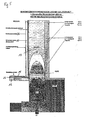
- the schematic representation according to Fig. 4 shows the effect of thermal insulation or the thermal conductivity or the heat transfer coefficient of a Dämmanowskinow invention, wherein the wall 13 is a brick wall and the Dämmanowskinowdler 25 and an insulating surface 15.
- the U-value of such a damping arrangement is approximately 0.03 W / Km 2 .
- Fig. 5 shows the properties of a Dämman extract invention on the inside of a wall 13, in which also the rising from the bottom of cold in the wall 13 is taken into account.
- the Dämman extract further includes a Kondensatewandler 25 and an insulating surface 15 both on the ground and on the wall 13 itself.
- An outer insulation is not provided on the outside of the wall 13 is merely applied a conventional plaster.
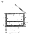
- Fig. 6 shows the different application variants of the insulating elements or the Dämman extract invention.
- the house shown here schematically in cross-section shows different Dämmfeaturen or Dämman extracten on different walls and different floor surfaces or sectors.
- the representation in Fig. 6 is merely exemplary and serves to illustrate the different applications, which are summarized in a common drawing only for the sake of clarity.
- the existing of the insulating elements 1 insulating surface 15 can be mounted as needed on the inner walls or on the floor or even on the outer walls. Visible is that not only interior or exterior walls, but Stairways, flat roofs, canal systems or pitched roofs with such an insulating surface 15 can be configured. Especially in old buildings between the wall 13 and the insulating surface 15, a condensate converter 25 is interposed.
- FIGS. 7 to 10 show alternatively configured insulation elements 1 in cross section, wherein each insulating element 1 consist essentially of a relatively thin-walled profiled Hüllwandung 8, which is closed on all sides substantially and surrounds an evacuated or evacuated cavity 2.
- the evacuated cavity 2 is empty and not by an additional insulating material, for example, a foam od.
- Filled The vacuum extends into the fine vacuum range, ie, approximately between 10 -3 mbar and 1 mbar.
- the insulation element 1 is substantially plate-shaped or parallelepiped-shaped, wherein the size can vary. As a rule, these are easy-to-handle tiles, plates, panels or bricks.
- the thickness of an insulating element 1 is in the range of about 1 to 3 cm with a maximum thickness of about 5 cm. In essence, the insulating element 1 is flat, but alternatively it can also be curved in order to adapt to a curvy course of the wall.
- the insulating element 1 has a flat outer surface 6, which is usually facing the viewer and the underlying wall 13 is turned away.
- the lower surface 3 On the opposite side of the insulating element 1 is the lower surface 3, which is facing in the assembly of the wall 13.
- rear ventilation means 4 are provided, which enable and effect a ventilation or venting or removal of water vapor with correct installation.
- the rear ventilation means 4 are integrally formed in the lower surface 3 or formed by the lower surface 3 is designed profiled accordingly.
- a grid-like ventilation network is formed in which a larger number of channels 4 intersect each other.
- the channels 4 are perpendicular to each other, whereby a corresponding regular pattern is drawn on the lower surface 3. Remain from the lower surface 3 projecting squares or rectangles, which ultimately abut the wall 13 and are glued thereto.
- the height of the channels 4 is a maximum of 5 mm, whereby no convection can take place in this area.
- the rear ventilation system can also be formed by other channel guides, for example by the formation of knobs or elevations the lower surface 3, but it is advantageous if the channels 4 are open on both sides and dead ends are avoided as possible. In addition, it is advantageous if the channels 4, as in the present embodiments, each open into opposite end faces 9 and thus extend over the entire length or width of the insulating element 1. In this way, an effective removal of any accumulating moisture can be accomplished.
- the evacuation of the cavity 2 to coarse or fine vacuum can be accomplished by the manufacturer by the insulation elements 1 are already evacuated in the course of the manufacturing process or are already produced under vacuum. This can be controlled, for example, in a blow molding process in which the insulating elements 1 are produced in one piece.
- the insulating elements 1 shown in the drawings are essentially all formed in one piece or in one piece by blow molding. Alternatively, however, it can be provided that the insulating elements 1 be two-part or multi-part, by first the individual parts are produced, which are then, optionally combined under vacuum conditions, to the finished insulating element 1.
- an insulation element 1 also subsequently ie after completion evacuate by a valve 10 is installed.
- a check valve 10 in the side wall or end face 9, whereby it is stored protected in the creation of a uniform insulating surface.
- an evacuated insulation element 1 can also be subsequently aerated again, without destroying the structural integrity, for example by tapping, etc.
- Such a ventilated insulating element 1 can be used as a functional element 1 ', as described later.
- reinforcing ribs 5 which protrude inwardly into the cavity 2. These reinforcing ribs 5 serve to increase the structural integrity, in particular against treading loads, and make such an insulating element 1 also usable for the floor area.
- FIG. 9 An alternative embodiment is in Fig. 9 described, in which the cavity 2 is domed in the region of the treading load or the inner side 7 is curved and laterally reinforced material.
- the insulating element 1 in particular in the cavity 2 or on the lower surface 3, can, not shown here, means for reducing the heat radiation can be arranged.
- metallic foils and / or vapor-deposited metallic coatings are possible which can reflect and / or absorb the infrared radiation.
- the films or coatings are advantageously arranged on both opposite inner surfaces of the cavity 2. In order not to create any additional thermal bridges due to the highly thermally conductive coatings, the two coatings should not be adjacent to one another and should be spaced apart from one another.
- the insulating elements 1, in the Fig. 7 to 16 are shown are preferably made of plastic, in particular fiber-reinforced thermosets, polyester or polyamides are used.
- insulating elements 1 made of plastic are easier to produce and, on the other hand, due to their low conductivity values, they offer an inherently higher insulating effect.
- connecting means 11 are formed in the end faces, which make it possibleraitzustecken or connect together a plurality of insulating elements 1 via corresponding connecting means 11.
- Fig. 7 to 9 These are stepwise offset connecting means in the form of stepped rabbets, which extend the gas passageway through the groove.
- Fig. 10 also interlocking tongue-and-groove systems are designed to ensure an actual mating and allow a floating structure or a composite.
- the insulating elements 1 are integrally and integrally formed in the Hüllwandung 8, since this is easier to manufacture.
- a damping arrangement can be created in which the individual insulating elements 1 are mounted on a wall 13 to be insulated.
- the individual insulating elements 1 thereby form a continuous closed insulating surface 15, which is advantageously air and / or moisture-proof.
- the insulating surface 15 is created from a multiplicity of insulation elements 1 assembled in two dimensions with one another via their end surfaces 9.
- the lower surfaces 3 of the insulating elements 1 with the rear ventilation means or channels 4 are facing the wall 13. In this way, a ventilation network for the removal of water vapor or moisture from this sensitive area between wall 13 and insulating surface 15 is formed.
- a further layer specifically a functional surface 20, is provided.
- the functional surface 20 is formed as a continuous closed surface and is arranged or glued to the surface 6 of the insulating surface 15.
- the functional surface 20 consists of a multiplicity of functional elements 1 'connected to one another via their end surfaces 9'.
- the functional elements 1 ' are constructed essentially identical to the insulating elements 1. The only difference between the insulating elements 1 and the functional elements 1 'is that the functional elements 1' are not evacuated and filled with air.
- the functional elements 1 ' can also be filled with further insulating materials, whereby, for example, an additional protection against radiant heat can be created by using an absorbent insulating material.
- the individual functional elements 1 'and the functional surface 20 are aligned with respect to the insulating surface 15 such that the connecting lines or grooves between the individual elements of the respective surface are not directly above the other, but are arranged offset to one another. It is particularly advantageous if the lateral distances are maximally offset from each other and the grooves are spaced as far as possible from each other, whereby the air path of the moist air penetrating through these gaps is maximally extended.
- a functional coating 30 in the form of a continuous, possibly dense, carpet, anti-slip coating or parquet floor etc. placed on the functional surface 20.
- Fig. 12 an alternative embodiment is shown, the basic structure of Fig. 11 maintains.
- the outer, the wall 13 averted surface of the functional surface 20 and the individual functional elements 1 'is perforated or has a plurality of regularly distributed through holes or openings 31.
- passage connections 32 are formed in the individual functional elements 1 'at their end faces or side surfaces 9', whereby between the individual functional elements 1 'of the functional surface 20, a gas exchange or passage is ensured.
- an air flow 33 can be generated which exits through the openings 31 (see arrow 33 in FIG Fig. 12 ). This allows the room temperature and humidity in the room to be regulated, for example when an air conditioning system is connected at low flow temperature.
- venting devices 29 made of an air-permeable material or in the form of channels are incorporated on the side edges or in the interior of the insulating surface 15 and / or the functional surface 20.
- venting devices 29 open the venting channels 4, whereby the discharged moisture can escape and the rear ventilation is enabled.
- a good insulation effect is given, whereby a use as a bottom plate in the basement is possible.
- Fig. 13a shows the possibility of using the insulating elements 1 with cavity on a flat roof of a new building.
- On the wall 13 of the flat roof in the form of a concrete ceiling screed is applied.
- the insulating surface 15 is laid, which in turn is covered by a functional coating 30 in the form of a waterproof roof seal.
- Both the insulating surface 15 and the functional coating 30 are pulled up to the edge regions of the roof and the insulating surface 15 also extends over the horizontal region of the outermost roof region up to the vertically sloping outer wall or up to full thermal protection.
- the moisture exits the ventilation channels 4 in the region of the outer wall and diffuses into the atmosphere.
- the condensate converter 25 is not shown here.
- Fig. 13b shows a renovation of a flat roof in an old building.
- a vapor barrier is applied on the wall 13 in the form of a concrete ceiling.
- a vapor barrier is applied on the wall 13 in the form of a concrete ceiling.
- an old insulation and an old roof seal arranged. Holes are perforated into these old seals as well as into the vapor barrier to open the moisture trap between the vapor barrier and the other building layers and allow the moisture to escape.
- the vacuum insulation elements 1 and a function coating 30 are applied in the usual way. This is the only way to dissipate the moisture escaping from the old insulation. The old damp insulation dries out completely in this way again.
- Fig. 14 shows the effect of thermal insulation or the thermal conductivity or the heat transfer coefficient of a Dämmanowski, wherein the wall 13 is a brick wall and the Dämmanowskilich 25, an evacuated insulating surface 15 and a functional surface 20.
- the U-value of such a damping arrangement is approximately 0.02 W / Km 2 .
- Fig. 15 shows a Dämman Mr.
- the Dämman Mr. 15 further includes a Kondensatewandler 25, an evacuated insulating surface 15 and a function coating 30 both on the ground and on the wall 13 itself.
- An outer insulation is not provided on the outer wall is merely applied a conventional plaster.
- Fig. 16 shows the different application variants of the invention Dämmimplantation or Dämman extract.
- the house shown here schematically in cross-section shows different Dämmfeaturen or Dämman extracten on different walls and different floor surfaces or sectors.
- the representation in Fig. 16 is merely exemplary and serves to illustrate the different applications, which are summarized in a common drawing only for the sake of clarity.
- the existing of the evacuated insulation elements 1 insulating surface 15 can be mounted as needed on the inner walls or on the floor or even on the outer walls. It can be seen that not only interior or exterior walls, but also stairs, flat roofs, duct systems or pitched roofs can be configured with such an insulating surface 15. If necessary, especially in old buildings, between the wall 13 and the insulating surface 15, a condensate converter 25 may be interposed.
- the insulating surface 15 may at most be covered by functional surfaces 20 in the form of air-filled functional elements 1 ', which may also be mounted both inside and outside.
- the individual insulating elements 1 and / or the functional elements 1 ' can also be fastened on their upper side to a flexible film, e.g. be glued, optionally in already assembled configuration as insulating surface 15 or functional surface 20. As a result, these are arranged on a rollable matrix and can be quickly and easily, for example, for roof insulation, laid. In this context, it is advantageous if the connections between the individual insulating elements 1 are movable or the insulating elements 1 against each other from the plane of the insulating surface 15 are pivoted out.
Landscapes
- Engineering & Computer Science (AREA)
- Architecture (AREA)
- Civil Engineering (AREA)
- Structural Engineering (AREA)
- Physics & Mathematics (AREA)
- Acoustics & Sound (AREA)
- Electromagnetism (AREA)
- Building Environments (AREA)
Applications Claiming Priority (2)
| Application Number | Priority Date | Filing Date | Title |
|---|---|---|---|
| AT17872008A AT507427B1 (de) | 2008-11-18 | 2008-11-18 | Dämmelement |
| AT0031609U AT10909U3 (de) | 2008-11-18 | 2009-05-14 | Dämmanordnung |
Publications (3)
| Publication Number | Publication Date |
|---|---|
| EP2186958A2 true EP2186958A2 (fr) | 2010-05-19 |
| EP2186958A3 EP2186958A3 (fr) | 2013-03-27 |
| EP2186958B1 EP2186958B1 (fr) | 2015-09-16 |
Family
ID=41668399
Family Applications (1)
| Application Number | Title | Priority Date | Filing Date |
|---|---|---|---|
| EP09450218.4A Active EP2186958B1 (fr) | 2008-11-18 | 2009-11-18 | Elément d'isolation |
Country Status (1)
| Country | Link |
|---|---|
| EP (1) | EP2186958B1 (fr) |
Cited By (6)
| Publication number | Priority date | Publication date | Assignee | Title |
|---|---|---|---|---|
| EP2860319A1 (fr) * | 2013-10-11 | 2015-04-15 | Daw Se | Composé d'isolation thermique et zone composite d'isolation thermique ainsi que structure murale comprenant le composé d'isolation thermique ou la zone composite d'isolation thermique et procédé de fabrication de structures murales |
| DE202019100385U1 (de) | 2018-01-25 | 2019-03-20 | Steinbacher Dämmstoff Gesellschaft m.b.H. | Dämmplatte |
| DE202019102015U1 (de) | 2018-04-13 | 2019-04-24 | Steinbacher Dämmstoff Gesellschaft m.b.H. | Hausdach mit Wasserableitung |
| WO2019224257A1 (fr) | 2018-05-22 | 2019-11-28 | Saint-Gobain Isover | Élément d'isolation thermique, construction de bâtiment et procédé empêchant la détérioration due à l'humidité au niveau d'un bâtiment |
| US20200353716A1 (en) * | 2017-11-28 | 2020-11-12 | Dow Global Technologies Llc | Polyurethane-based insulation board |
| EP4650543A1 (fr) * | 2024-05-15 | 2025-11-19 | btf Holding UG (haftungsbeschränkt) | Dispositif d'étanchéité pour toit |
Family Cites Families (4)
| Publication number | Priority date | Publication date | Assignee | Title |
|---|---|---|---|---|
| FR614700A (fr) * | 1925-08-29 | 1926-12-20 | Dispositif perfectionné de revêtement de murs | |
| CH648888A5 (de) * | 1982-09-07 | 1985-04-15 | Haering & Kies Ag | Hinterlueftete isolierfassade. |
| DE3414249A1 (de) * | 1984-04-14 | 1986-01-02 | Walter 5093 Burscheid Gutjahr jun. | Draenagematten, hinterlueftungsmatten und hinterlueftete waermedaemmplatten fuer das bauwesen |
| AT505298B1 (de) * | 2007-04-19 | 2008-12-15 | Karl Ing Kleebinder | Plattenförmiges verkleidungselement für eine mauer und mauerverkleidung |
-
2009
- 2009-11-18 EP EP09450218.4A patent/EP2186958B1/fr active Active
Cited By (7)
| Publication number | Priority date | Publication date | Assignee | Title |
|---|---|---|---|---|
| EP2860319A1 (fr) * | 2013-10-11 | 2015-04-15 | Daw Se | Composé d'isolation thermique et zone composite d'isolation thermique ainsi que structure murale comprenant le composé d'isolation thermique ou la zone composite d'isolation thermique et procédé de fabrication de structures murales |
| US20200353716A1 (en) * | 2017-11-28 | 2020-11-12 | Dow Global Technologies Llc | Polyurethane-based insulation board |
| US11745465B2 (en) * | 2017-11-28 | 2023-09-05 | Dow Global Technologies Llc | Polyurethane-based insulation board |
| DE202019100385U1 (de) | 2018-01-25 | 2019-03-20 | Steinbacher Dämmstoff Gesellschaft m.b.H. | Dämmplatte |
| DE202019102015U1 (de) | 2018-04-13 | 2019-04-24 | Steinbacher Dämmstoff Gesellschaft m.b.H. | Hausdach mit Wasserableitung |
| WO2019224257A1 (fr) | 2018-05-22 | 2019-11-28 | Saint-Gobain Isover | Élément d'isolation thermique, construction de bâtiment et procédé empêchant la détérioration due à l'humidité au niveau d'un bâtiment |
| EP4650543A1 (fr) * | 2024-05-15 | 2025-11-19 | btf Holding UG (haftungsbeschränkt) | Dispositif d'étanchéité pour toit |
Also Published As
| Publication number | Publication date |
|---|---|
| EP2186958B1 (fr) | 2015-09-16 |
| EP2186958A3 (fr) | 2013-03-27 |
Similar Documents
| Publication | Publication Date | Title |
|---|---|---|
| EP2186958B1 (fr) | Elément d'isolation | |
| CN101109194B (zh) | 木结构单向透气保温墙体 | |
| EP2169132A2 (fr) | Élément de construction en forme de panneau | |
| DE4338185C2 (de) | Verfahren zur Herstellung eines Fertighauses | |
| EP2143849A2 (fr) | Habillage mural et procédé d'assèchement d'une surface murale | |
| AT507427B1 (de) | Dämmelement | |
| DE102013210798B3 (de) | Vorrichtung für eine Durchführung durch eine Wand eines Fertighauses sowie Verfahren zur Anbringung einer derartigen Durchführung an einem Bauelement eines Fertighauses | |
| WO2007082521A2 (fr) | Brique isolante perforée de grande taille et son procédé d'utilisation | |
| EP1365082B1 (fr) | Panneau | |
| EP0976886B1 (fr) | Elément de construction pour revêtement de toiture et/ou de façade et son procédé de fabrication | |
| DE2849300A1 (de) | Integriertes haus | |
| DE3437767A1 (de) | Draenagematten zum einsatz unter horizontalen bodenbelaegen, insbesondere auf terrassen und balkonen | |
| EP2706159B1 (fr) | Procédé destiné à réduire ou éliminer les dégâts ou formations de moisissures et/ou d'humidité dans des zones à isolation thermique, et les batiments et parties de batiments proteges contre les dégâts ou formations de moisissures et/ou d'humidité | |
| EP0805902B1 (fr) | Structure de plancher, de plafond ou de cloison assurant une tres bonne isolation thermique | |
| DE102016117032A1 (de) | Deckschichtbauelement und Trockenbausystem | |
| EP1905920A1 (fr) | Structure de sol composite pour système de chauffage au sol | |
| Jarosz | Insulating timber-framed walls of historical buildings using modern technologies and materials | |
| DE102012106778A1 (de) | Verfahren zur Behandlung von ultrahochfestem Beton sowie eine Vorrichtung hierfür | |
| DE19833559A1 (de) | Zwei- oder mehrwandige Konstruktion für Wände, Decken oder Dächer | |
| DE102005002571A1 (de) | Hygrothermisches Verbundsystem für Bauwerke | |
| DE202024000507U1 (de) | Dämmfliesen und deren Verwendung | |
| AT519367A4 (de) | Wand für ein gebäude | |
| DE20114397U1 (de) | Niedrigenergiehaus | |
| EP1224360B1 (fr) | Materiau de construction et d'isolation | |
| DE102012021440A1 (de) | Niedrigenergiehaus |
Legal Events
| Date | Code | Title | Description |
|---|---|---|---|
| PUAI | Public reference made under article 153(3) epc to a published international application that has entered the european phase |
Free format text: ORIGINAL CODE: 0009012 |
|
| AK | Designated contracting states |
Kind code of ref document: A2 Designated state(s): AT BE BG CH CY CZ DE DK EE ES FI FR GB GR HR HU IE IS IT LI LT LU LV MC MK MT NL NO PL PT RO SE SI SK SM TR |
|
| AX | Request for extension of the european patent |
Extension state: AL BA RS |
|
| PUAL | Search report despatched |
Free format text: ORIGINAL CODE: 0009013 |
|
| AK | Designated contracting states |
Kind code of ref document: A3 Designated state(s): AT BE BG CH CY CZ DE DK EE ES FI FR GB GR HR HU IE IS IT LI LT LU LV MC MK MT NL NO PL PT RO SE SI SK SM TR |
|
| AX | Request for extension of the european patent |
Extension state: AL BA RS |
|
| RIC1 | Information provided on ipc code assigned before grant |
Ipc: E04B 1/76 20060101ALI20130219BHEP Ipc: E04B 1/80 20060101AFI20130219BHEP Ipc: E04F 13/00 20060101ALI20130219BHEP |
|
| 17P | Request for examination filed |
Effective date: 20130924 |
|
| RBV | Designated contracting states (corrected) |
Designated state(s): AT BE BG CH CY CZ DE DK EE ES FI FR GB GR HR HU IE IS IT LI LT LU LV MC MK MT NL NO PL PT RO SE SI SK SM TR |
|
| 17Q | First examination report despatched |
Effective date: 20140121 |
|
| GRAP | Despatch of communication of intention to grant a patent |
Free format text: ORIGINAL CODE: EPIDOSNIGR1 |
|
| INTG | Intention to grant announced |
Effective date: 20150408 |
|
| GRAS | Grant fee paid |
Free format text: ORIGINAL CODE: EPIDOSNIGR3 |
|
| GRAA | (expected) grant |
Free format text: ORIGINAL CODE: 0009210 |
|
| AK | Designated contracting states |
Kind code of ref document: B1 Designated state(s): AT BE BG CH CY CZ DE DK EE ES FI FR GB GR HR HU IE IS IT LI LT LU LV MC MK MT NL NO PL PT RO SE SI SK SM TR |
|
| REG | Reference to a national code |
Ref country code: GB Ref legal event code: FG4D Free format text: NOT ENGLISH |
|
| REG | Reference to a national code |
Ref country code: CH Ref legal event code: EP |
|
| REG | Reference to a national code |
Ref country code: IE Ref legal event code: FG4D Free format text: LANGUAGE OF EP DOCUMENT: GERMAN |
|
| REG | Reference to a national code |
Ref country code: AT Ref legal event code: REF Ref document number: 749963 Country of ref document: AT Kind code of ref document: T Effective date: 20151015 |
|
| REG | Reference to a national code |
Ref country code: DE Ref legal event code: R096 Ref document number: 502009011581 Country of ref document: DE |
|
| REG | Reference to a national code |
Ref country code: FR Ref legal event code: PLFP Year of fee payment: 7 |
|
| REG | Reference to a national code |
Ref country code: CH Ref legal event code: NV Representative=s name: PATWIL AG, CH |
|
| REG | Reference to a national code |
Ref country code: NL Ref legal event code: MP Effective date: 20150916 |
|
| PG25 | Lapsed in a contracting state [announced via postgrant information from national office to epo] |
Ref country code: GR Free format text: LAPSE BECAUSE OF FAILURE TO SUBMIT A TRANSLATION OF THE DESCRIPTION OR TO PAY THE FEE WITHIN THE PRESCRIBED TIME-LIMIT Effective date: 20151217 Ref country code: LV Free format text: LAPSE BECAUSE OF FAILURE TO SUBMIT A TRANSLATION OF THE DESCRIPTION OR TO PAY THE FEE WITHIN THE PRESCRIBED TIME-LIMIT Effective date: 20150916 Ref country code: FI Free format text: LAPSE BECAUSE OF FAILURE TO SUBMIT A TRANSLATION OF THE DESCRIPTION OR TO PAY THE FEE WITHIN THE PRESCRIBED TIME-LIMIT Effective date: 20150916 Ref country code: NO Free format text: LAPSE BECAUSE OF FAILURE TO SUBMIT A TRANSLATION OF THE DESCRIPTION OR TO PAY THE FEE WITHIN THE PRESCRIBED TIME-LIMIT Effective date: 20151216 Ref country code: LT Free format text: LAPSE BECAUSE OF FAILURE TO SUBMIT A TRANSLATION OF THE DESCRIPTION OR TO PAY THE FEE WITHIN THE PRESCRIBED TIME-LIMIT Effective date: 20150916 |
|
| REG | Reference to a national code |
Ref country code: LT Ref legal event code: MG4D |
|
| PG25 | Lapsed in a contracting state [announced via postgrant information from national office to epo] |
Ref country code: HR Free format text: LAPSE BECAUSE OF FAILURE TO SUBMIT A TRANSLATION OF THE DESCRIPTION OR TO PAY THE FEE WITHIN THE PRESCRIBED TIME-LIMIT Effective date: 20150916 Ref country code: SE Free format text: LAPSE BECAUSE OF FAILURE TO SUBMIT A TRANSLATION OF THE DESCRIPTION OR TO PAY THE FEE WITHIN THE PRESCRIBED TIME-LIMIT Effective date: 20150916 |
|
| PG25 | Lapsed in a contracting state [announced via postgrant information from national office to epo] |
Ref country code: NL Free format text: LAPSE BECAUSE OF FAILURE TO SUBMIT A TRANSLATION OF THE DESCRIPTION OR TO PAY THE FEE WITHIN THE PRESCRIBED TIME-LIMIT Effective date: 20150916 |
|
| PG25 | Lapsed in a contracting state [announced via postgrant information from national office to epo] |
Ref country code: SK Free format text: LAPSE BECAUSE OF FAILURE TO SUBMIT A TRANSLATION OF THE DESCRIPTION OR TO PAY THE FEE WITHIN THE PRESCRIBED TIME-LIMIT Effective date: 20150916 Ref country code: CZ Free format text: LAPSE BECAUSE OF FAILURE TO SUBMIT A TRANSLATION OF THE DESCRIPTION OR TO PAY THE FEE WITHIN THE PRESCRIBED TIME-LIMIT Effective date: 20150916 Ref country code: EE Free format text: LAPSE BECAUSE OF FAILURE TO SUBMIT A TRANSLATION OF THE DESCRIPTION OR TO PAY THE FEE WITHIN THE PRESCRIBED TIME-LIMIT Effective date: 20150916 Ref country code: IS Free format text: LAPSE BECAUSE OF FAILURE TO SUBMIT A TRANSLATION OF THE DESCRIPTION OR TO PAY THE FEE WITHIN THE PRESCRIBED TIME-LIMIT Effective date: 20160116 Ref country code: ES Free format text: LAPSE BECAUSE OF FAILURE TO SUBMIT A TRANSLATION OF THE DESCRIPTION OR TO PAY THE FEE WITHIN THE PRESCRIBED TIME-LIMIT Effective date: 20150916 |
|
| PG25 | Lapsed in a contracting state [announced via postgrant information from national office to epo] |
Ref country code: PL Free format text: LAPSE BECAUSE OF FAILURE TO SUBMIT A TRANSLATION OF THE DESCRIPTION OR TO PAY THE FEE WITHIN THE PRESCRIBED TIME-LIMIT Effective date: 20150916 Ref country code: RO Free format text: LAPSE BECAUSE OF FAILURE TO SUBMIT A TRANSLATION OF THE DESCRIPTION OR TO PAY THE FEE WITHIN THE PRESCRIBED TIME-LIMIT Effective date: 20150916 |
|
| REG | Reference to a national code |
Ref country code: DE Ref legal event code: R097 Ref document number: 502009011581 Country of ref document: DE |
|
| PG25 | Lapsed in a contracting state [announced via postgrant information from national office to epo] |
Ref country code: MC Free format text: LAPSE BECAUSE OF FAILURE TO SUBMIT A TRANSLATION OF THE DESCRIPTION OR TO PAY THE FEE WITHIN THE PRESCRIBED TIME-LIMIT Effective date: 20150916 Ref country code: LU Free format text: LAPSE BECAUSE OF FAILURE TO SUBMIT A TRANSLATION OF THE DESCRIPTION OR TO PAY THE FEE WITHIN THE PRESCRIBED TIME-LIMIT Effective date: 20151118 |
|
| PLBE | No opposition filed within time limit |
Free format text: ORIGINAL CODE: 0009261 |
|
| STAA | Information on the status of an ep patent application or granted ep patent |
Free format text: STATUS: NO OPPOSITION FILED WITHIN TIME LIMIT |
|
| 26N | No opposition filed |
Effective date: 20160617 |
|
| REG | Reference to a national code |
Ref country code: IE Ref legal event code: MM4A |
|
| PG25 | Lapsed in a contracting state [announced via postgrant information from national office to epo] |
Ref country code: DK Free format text: LAPSE BECAUSE OF FAILURE TO SUBMIT A TRANSLATION OF THE DESCRIPTION OR TO PAY THE FEE WITHIN THE PRESCRIBED TIME-LIMIT Effective date: 20150916 |
|
| PG25 | Lapsed in a contracting state [announced via postgrant information from national office to epo] |
Ref country code: IE Free format text: LAPSE BECAUSE OF NON-PAYMENT OF DUE FEES Effective date: 20151118 |
|
| REG | Reference to a national code |
Ref country code: FR Ref legal event code: PLFP Year of fee payment: 8 |
|
| PG25 | Lapsed in a contracting state [announced via postgrant information from national office to epo] |
Ref country code: SI Free format text: LAPSE BECAUSE OF FAILURE TO SUBMIT A TRANSLATION OF THE DESCRIPTION OR TO PAY THE FEE WITHIN THE PRESCRIBED TIME-LIMIT Effective date: 20150916 |
|
| PG25 | Lapsed in a contracting state [announced via postgrant information from national office to epo] |
Ref country code: SM Free format text: LAPSE BECAUSE OF FAILURE TO SUBMIT A TRANSLATION OF THE DESCRIPTION OR TO PAY THE FEE WITHIN THE PRESCRIBED TIME-LIMIT Effective date: 20150916 Ref country code: BG Free format text: LAPSE BECAUSE OF FAILURE TO SUBMIT A TRANSLATION OF THE DESCRIPTION OR TO PAY THE FEE WITHIN THE PRESCRIBED TIME-LIMIT Effective date: 20150916 Ref country code: HU Free format text: LAPSE BECAUSE OF FAILURE TO SUBMIT A TRANSLATION OF THE DESCRIPTION OR TO PAY THE FEE WITHIN THE PRESCRIBED TIME-LIMIT; INVALID AB INITIO Effective date: 20091118 |
|
| PG25 | Lapsed in a contracting state [announced via postgrant information from national office to epo] |
Ref country code: CY Free format text: LAPSE BECAUSE OF FAILURE TO SUBMIT A TRANSLATION OF THE DESCRIPTION OR TO PAY THE FEE WITHIN THE PRESCRIBED TIME-LIMIT Effective date: 20150916 |
|
| PG25 | Lapsed in a contracting state [announced via postgrant information from national office to epo] |
Ref country code: MT Free format text: LAPSE BECAUSE OF FAILURE TO SUBMIT A TRANSLATION OF THE DESCRIPTION OR TO PAY THE FEE WITHIN THE PRESCRIBED TIME-LIMIT Effective date: 20150916 Ref country code: TR Free format text: LAPSE BECAUSE OF FAILURE TO SUBMIT A TRANSLATION OF THE DESCRIPTION OR TO PAY THE FEE WITHIN THE PRESCRIBED TIME-LIMIT Effective date: 20150916 |
|
| REG | Reference to a national code |
Ref country code: FR Ref legal event code: PLFP Year of fee payment: 9 |
|
| REG | Reference to a national code |
Ref country code: CH Ref legal event code: NV Representative=s name: KAMINSKI HARMANN PATENTANWAELTE AG, CH |
|
| PG25 | Lapsed in a contracting state [announced via postgrant information from national office to epo] |
Ref country code: MK Free format text: LAPSE BECAUSE OF FAILURE TO SUBMIT A TRANSLATION OF THE DESCRIPTION OR TO PAY THE FEE WITHIN THE PRESCRIBED TIME-LIMIT Effective date: 20150916 Ref country code: PT Free format text: LAPSE BECAUSE OF FAILURE TO SUBMIT A TRANSLATION OF THE DESCRIPTION OR TO PAY THE FEE WITHIN THE PRESCRIBED TIME-LIMIT Effective date: 20150916 |
|
| REG | Reference to a national code |
Ref country code: DE Ref legal event code: R082 Ref document number: 502009011581 Country of ref document: DE Representative=s name: MUELLER, THOMAS, DIPL.-ING., DE |
|
| PGFP | Annual fee paid to national office [announced via postgrant information from national office to epo] |
Ref country code: GB Payment date: 20201119 Year of fee payment: 12 Ref country code: FR Payment date: 20201120 Year of fee payment: 12 |
|
| PGFP | Annual fee paid to national office [announced via postgrant information from national office to epo] |
Ref country code: BE Payment date: 20201125 Year of fee payment: 12 |
|
| GBPC | Gb: european patent ceased through non-payment of renewal fee |
Effective date: 20211118 |
|
| PG25 | Lapsed in a contracting state [announced via postgrant information from national office to epo] |
Ref country code: BE Free format text: LAPSE BECAUSE OF NON-PAYMENT OF DUE FEES Effective date: 20211130 |
|
| REG | Reference to a national code |
Ref country code: BE Ref legal event code: MM Effective date: 20211130 |
|
| PG25 | Lapsed in a contracting state [announced via postgrant information from national office to epo] |
Ref country code: GB Free format text: LAPSE BECAUSE OF NON-PAYMENT OF DUE FEES Effective date: 20211118 |
|
| PG25 | Lapsed in a contracting state [announced via postgrant information from national office to epo] |
Ref country code: FR Free format text: LAPSE BECAUSE OF NON-PAYMENT OF DUE FEES Effective date: 20211130 |
|
| PGFP | Annual fee paid to national office [announced via postgrant information from national office to epo] |
Ref country code: IT Payment date: 20221124 Year of fee payment: 14 |
|
| PGFP | Annual fee paid to national office [announced via postgrant information from national office to epo] |
Ref country code: CH Payment date: 20221121 Year of fee payment: 14 |
|
| REG | Reference to a national code |
Ref country code: CH Ref legal event code: PL |
|
| PG25 | Lapsed in a contracting state [announced via postgrant information from national office to epo] |
Ref country code: CH Free format text: LAPSE BECAUSE OF NON-PAYMENT OF DUE FEES Effective date: 20231130 |
|
| PG25 | Lapsed in a contracting state [announced via postgrant information from national office to epo] |
Ref country code: CH Free format text: LAPSE BECAUSE OF NON-PAYMENT OF DUE FEES Effective date: 20231130 |
|
| PG25 | Lapsed in a contracting state [announced via postgrant information from national office to epo] |
Ref country code: IT Free format text: LAPSE BECAUSE OF NON-PAYMENT OF DUE FEES Effective date: 20231118 |
|
| PG25 | Lapsed in a contracting state [announced via postgrant information from national office to epo] |
Ref country code: IT Free format text: LAPSE BECAUSE OF NON-PAYMENT OF DUE FEES Effective date: 20231118 |
|
| PGFP | Annual fee paid to national office [announced via postgrant information from national office to epo] |
Ref country code: DE Payment date: 20241121 Year of fee payment: 16 |
|
| PGFP | Annual fee paid to national office [announced via postgrant information from national office to epo] |
Ref country code: AT Payment date: 20241212 Year of fee payment: 16 |