EP2186967A2 - Dispositif de montage pour une machine manuelle - Google Patents
Dispositif de montage pour une machine manuelle Download PDFInfo
- Publication number
- EP2186967A2 EP2186967A2 EP20090014359 EP09014359A EP2186967A2 EP 2186967 A2 EP2186967 A2 EP 2186967A2 EP 20090014359 EP20090014359 EP 20090014359 EP 09014359 A EP09014359 A EP 09014359A EP 2186967 A2 EP2186967 A2 EP 2186967A2
- Authority
- EP
- European Patent Office
- Prior art keywords
- hand machine
- cleaned
- cleaning
- mounting device
- rollers
- Prior art date
- Legal status (The legal status is an assumption and is not a legal conclusion. Google has not performed a legal analysis and makes no representation as to the accuracy of the status listed.)
- Withdrawn
Links
- 238000004140 cleaning Methods 0.000 claims abstract description 86
- 239000006223 plastic coating Substances 0.000 claims abstract description 5
- 238000003466 welding Methods 0.000 claims description 3
- 229910000746 Structural steel Inorganic materials 0.000 claims description 2
- 238000009415 formwork Methods 0.000 description 23
- 238000000034 method Methods 0.000 description 18
- 239000000463 material Substances 0.000 description 11
- 238000004519 manufacturing process Methods 0.000 description 6
- 229920005372 Plexiglas® Polymers 0.000 description 4
- 239000004926 polymethyl methacrylate Substances 0.000 description 4
- 230000006978 adaptation Effects 0.000 description 3
- 229910052782 aluminium Inorganic materials 0.000 description 3
- XAGFODPZIPBFFR-UHFFFAOYSA-N aluminium Chemical compound [Al] XAGFODPZIPBFFR-UHFFFAOYSA-N 0.000 description 3
- 230000000694 effects Effects 0.000 description 3
- 239000002245 particle Substances 0.000 description 3
- 229910001209 Low-carbon steel Inorganic materials 0.000 description 2
- 229910052751 metal Inorganic materials 0.000 description 2
- 239000002184 metal Substances 0.000 description 2
- 239000007769 metal material Substances 0.000 description 2
- 239000003973 paint Substances 0.000 description 2
- 244000025254 Cannabis sativa Species 0.000 description 1
- 235000012766 Cannabis sativa ssp. sativa var. sativa Nutrition 0.000 description 1
- 235000012765 Cannabis sativa ssp. sativa var. spontanea Nutrition 0.000 description 1
- 241000196324 Embryophyta Species 0.000 description 1
- 239000004677 Nylon Substances 0.000 description 1
- 229910000831 Steel Inorganic materials 0.000 description 1
- 238000005299 abrasion Methods 0.000 description 1
- 230000004323 axial length Effects 0.000 description 1
- 235000009120 camo Nutrition 0.000 description 1
- 235000005607 chanvre indien Nutrition 0.000 description 1
- 238000010276 construction Methods 0.000 description 1
- 238000005520 cutting process Methods 0.000 description 1
- 230000001419 dependent effect Effects 0.000 description 1
- 238000011161 development Methods 0.000 description 1
- 230000018109 developmental process Effects 0.000 description 1
- 238000006073 displacement reaction Methods 0.000 description 1
- 238000005553 drilling Methods 0.000 description 1
- 239000013013 elastic material Substances 0.000 description 1
- 239000011487 hemp Substances 0.000 description 1
- 230000007774 longterm Effects 0.000 description 1
- 229920001778 nylon Polymers 0.000 description 1
- 230000002035 prolonged effect Effects 0.000 description 1
- 239000010959 steel Substances 0.000 description 1
Images


Classifications
-
- E—FIXED CONSTRUCTIONS
- E04—BUILDING
- E04G—SCAFFOLDING; FORMS; SHUTTERING; BUILDING IMPLEMENTS OR AIDS, OR THEIR USE; HANDLING BUILDING MATERIALS ON THE SITE; REPAIRING, BREAKING-UP OR OTHER WORK ON EXISTING BUILDINGS
- E04G19/00—Auxiliary treatment of forms, e.g. dismantling; Cleaning devices
- E04G19/006—Cleaning devices
-
- B—PERFORMING OPERATIONS; TRANSPORTING
- B08—CLEANING
- B08B—CLEANING IN GENERAL; PREVENTION OF FOULING IN GENERAL
- B08B1/00—Cleaning by methods involving the use of tools
- B08B1/30—Cleaning by methods involving the use of tools by movement of cleaning members over a surface
- B08B1/32—Cleaning by methods involving the use of tools by movement of cleaning members over a surface using rotary cleaning members
- B08B1/34—Cleaning by methods involving the use of tools by movement of cleaning members over a surface using rotary cleaning members rotating about an axis parallel to the surface
-
- B—PERFORMING OPERATIONS; TRANSPORTING
- B24—GRINDING; POLISHING
- B24B—MACHINES, DEVICES, OR PROCESSES FOR GRINDING OR POLISHING; DRESSING OR CONDITIONING OF ABRADING SURFACES; FEEDING OF GRINDING, POLISHING, OR LAPPING AGENTS
- B24B23/00—Portable grinding machines, e.g. hand-guided; Accessories therefor
- B24B23/005—Auxiliary devices used in connection with portable grinding machines, e.g. holders
-
- B—PERFORMING OPERATIONS; TRANSPORTING
- B24—GRINDING; POLISHING
- B24B—MACHINES, DEVICES, OR PROCESSES FOR GRINDING OR POLISHING; DRESSING OR CONDITIONING OF ABRADING SURFACES; FEEDING OF GRINDING, POLISHING, OR LAPPING AGENTS
- B24B23/00—Portable grinding machines, e.g. hand-guided; Accessories therefor
- B24B23/02—Portable grinding machines, e.g. hand-guided; Accessories therefor with rotating grinding tools; Accessories therefor
- B24B23/028—Angle tools
Definitions
- the present invention relates to a mounting device for a hand machine, which can be used in the cleaning of an object used. Attachments may be arranged on the hand-held machine, preferably rigidly mounted to assist or carry out operations by the hand-held machine.
- the present invention is preferably used in the field of civil engineering and it can be supported with the attachment according to the invention, the cleaning of formwork elements.
- it is used in the cleaning of frames of concrete formwork systems, preferably for walls and ceilings.
- a factory-welded frame made of steel or aluminum is used.
- DE 3942784 A1 is a device for the treatment of frames, provided in the corners and fitting elements of concrete formwork, in which a slider in a special angle grinder is provided, the sliding member is displaceable in an upper part perpendicular to the cleaning surface and the upper part is mounted on a guide frame with skids.
- the sliding part is adjusted via a threaded rod with respect to the upper part.
- Cutting discs, cup brushes or nylon brushes can be attached to the special angle grinder and the distance of this surface to be cleaned can be precisely adjusted.
- the use of this device is limited to the application of the top of the surfaces to be cleaned.
- a disadvantage is the high weight due to the large number of angle grinder holding frame parts.
- an attachment machine for a hand machine which comprises: a base element which can be attached to the hand machine between the hand machine and a cleaning element that can be moved relative to the base element and driven by the hand machine, and at least one roller rotatably mounted on the base element an object to be cleaned is movable guided on at least one side, while the object to be cleaned can be cleaned at least in sections by the cleaning element movable relative to the base element.
- a guide of the hand machine and thus of the cleaning element can be ensured along the object to be cleaned, whereby an improved cleaning effect can be achieved and lower fatigue occurring in the user.
- a linear movement of the cleaning element with respect to the base element can be generated and due to this relative movement of the object to be cleaned can be subjected to the cleaning process.
- the advantage of the linear movement is the targeted moving out in two directions of the removed particles from the object to be cleaned.
- the hand machine has a rotary drive over which the cleaning element is rotatable.
- a rotary drive over which the cleaning element is rotatable.
- conventional angle grinders can be used and a very intensive cleaning process can be achieved due to the constant high speed streaking due to the rotation.
- the invention is not limited thereto and it may also be a combination of rotational movement and linear movement generated by the hand machine on the cleaning element.
- the axis of rotation of the at least one roller runs essentially parallel to the axis of rotation of the cleaning element. In this way, tilting during the movement process on the object to be cleaned be prevented and a uniform cleaning process can be ensured.
- the base element has a support plate for the hand machine and at least one side attachment for receiving the roller.
- the platen takes up the hand machine and the side mount establishes a rigid connection of the platen to the axis of rotation of the roll.
- the side mount and / or the platen may be made of mild steel. In this way, a robust attachment can be implemented, which can withstand different weather conditions.
- the support plate and the at least one side attachment may be joined together by welding, whereby a simple and inexpensive connection method for producing the attachment device can be implemented.
- the hitch can be moved along the object to be cleaned with little abrasion during the cleaning process.
- the roller is preferably attached via a threaded rod to a side mount, so that at low axial length of the roller an effective guiding operation can take place and the side attachment with the roller can be easily connected.
- two rollers fixed to the base element, between which the object to be cleaned can be guided are provided at a predetermined distance. In this way, a limitation of the movement between the hitch and primitive to the direction of movement in both directions can be limited, whereby a safe cleaning process can be implemented.
- the object to be cleaned can be guided by the rollers during cleaning on its opposite side surfaces.
- the rollers can be guided by the rollers during cleaning on its opposite side surfaces.
- the axis of rotation of the cleaning element may be outside a plane defined by the axes of rotation of the two rollers. In this way, a mutual influence of cleaning process and leadership process can be prevented and a safe material discharge of the material to be cleaned removed material can be implemented.
- the distance between the two rollers is changeable, since in this way adaptation to different objects to be cleaned is possible.
- At least one of the two rollers may be mounted in a slot in at least one of the side fasteners of the base member, so that only the attachment of the rollers must be relaxed and a displacement of the axle must be made to make the adaptation to other frame members.
- At least one of the side fasteners of the base member may have at least two holes for receiving a roll in two different positions. This is advantageous if two different transverse dimensions of the frame members that are to be cleaned, are present and thus an accurate adjustment of the distance in the transverse direction of the roles makes sense.
- the geometric design of the base element can be adapted to the cleaning of frames of concrete formwork.
- further features of the formwork elements can be taken into account, such. B. further inclined surfaces, may be provided for the guide elements, such as. B other rollers with inclined axes.
- a recess for receiving a fastening means may be provided, via which the hand-held machine can be rigidly fastened to the base element.
- the hand machine does not have to be specially adapted to the cleaning process, but existing .Ausappelisme can be used on the hand machine for attachment of the hitch.
- a recess on the base member is arranged in such a manner that in this a fastening means for fixing the base member with respect to a receiving element of a handle for the hemp machine can be introduced. Since multiple recesses are provided for handles typically on angle grinders, a secure attachment of the hitch can be implemented using these recesses.
- a cover can be provided by the ejection of previously adhering to the object to be cleaned material in the axial direction of the rotary drive of the hand machine can be prevented. This increases the safety of the user.
- the cover may be U-shaped, so that ejection of previously adhering to the object to be cleaned material perpendicular to the axial direction of the rotary drive and perpendicular to the direction of movement of the object to be cleaned can be prevented. In this way, the movement is not hindered on the object to be cleaned.
- the cover is preferably made of Plexiglas or other translucent material. This allows the cleaning process to be closely monitored.
- the cover is formed of sheet metal, preferably center sheet, or other metallic material, a cover with high durability can be implemented with low production costs.
- the sheet is preferably made of aluminum, so that a cost-effective production is possible.
- the cleaning element is a brush, preferably a cup brush, so that the cleaning process can be carried out with low production costs and high efficiency.
- a cupped pot brush When using a cupped pot brush, a longer service life than with other Topbürstenart be implemented.
- the diameter of the cup brush is preferably greater than 10cm and less than 20cm to account for formwork elements, in particular frame elements used in construction.
- the hand machine is preferably an electric hand machine, since in this way with high efficiency and low weight cleaning process can be performed.
- the hand machine is more preferably an angle grinder, because due to the angular gear, the thickness of attachment to the hand machine can be made small and thus a compact cleaning device can be implemented.
- FIG. 1A to 4C are the hitch or sub-elements of this invention shown according to an embodiment. This embodiment will be explained in more detail below.
- Hand machine is understood here as a hand-held implement. It is preferred that a cleaning element is attached to this working device, in which a relative movement, for example with respect to the housing of the implement, can be generated, this relative movement is used for cleaning.
- the hand machine is preferably an electric hand machine, but can be driven in any other way, such. B. also by a gasoline engine. It is particularly advantageous if the electric hand machine has an angle gear, so that the drive axis preferably extends at right angles to the housing axis and thus in a compact device, a rotary drive of a tool is possible.
- the present invention is not limited to a rotary drive, for example, linear drive movements and other drive movements can be generated.
- linear drive movements for example, linear drive movements and other drive movements can be generated.
- angle grinder for an electric hand machine with bevel gear below the term “angle grinder” is used, this is synonymous with “cut-off” used here.
- FIGS. 1A to 1C show a basic element 1, which is attachable to the head of an angle grinder.
- the base element 1 has a support plate 2, on whose opposite sides to the same side of the support plate above side fasteners 4 and 6 are arranged.
- the basic element 1 is for attachment to a hand machine adapted, wherein the support plate 2 has a recess 8 into which a cylinder-like projection of the hand machine can be introduced.
- the present invention is not limited to a circular recess 8, but there may be any adjustment of the support plate to the hand machine, if a running of a drive axle is made possible by the support plate.
- the support plate 2 need not be disc-shaped, but it may also be an adaptation to an outer contour of the hand machine.
- the outer contour of the support plate 2 is also preferably adapted to the housing design of the hand machine, wherein an arcuate outer edge 10 of the support plate 2 can extend substantially parallel to the housing of the hand machine and a straight outer edge 12 is provided to abut with a housing edge of the hand machine be.
- the shapes of the edges 10 and 12 may be adapted to the particular design of the hand machine.
- the support plate 2 extension portions 14 and 16 via which the side mountings 4 and 6 are attached to the support plate 2.
- the invention is not limited to the fact that the support plate 2 and the side fasteners 4 and 6 are attached to each other as separate components, but these may also be provided integrally in the production.
- a side mount 6 is in plan view in FIG FIG. 2 shown.
- the side attachment 6 has a cylinder portion 18 and a flat portion 20, which terminates via an intermediate portion 22 to the cylinder portion 18.
- a mounting recess 24 is introduced, via which the hand machine is attached to the side mount. It is preferred that in the recess 24, a screw can be introduced and this can be introduced into a receptacle for a handle of the hand machine.
- a rod recess 26 extends substantially perpendicularly to the central axis of the fastening recesses 24, via which a threaded rod 28, which in FIG. 3 is shown in the side mount 6 can be fastened.
- the Threaded rod 28 can, as it is in Figure 1A is shown mounted over a lock nut 30 in the side mount, wherein the threaded rod 28 preferably around its projecting portion 28 a, the in Figure 1A is shown protruding from the side mount 6.
- a bore 34 is introduced, in which a roller 36 with the threaded rod 28 is connectable.
- the roller 36 is preferably rotatably attached to the threaded rod.
- the protruding section 28a is advantageous for the reason that a cleaning element can be provided in this area above the support plate 2.
- the rollers 36 are attached directly to the side mount.
- the rollers are arranged at a predetermined distance above the side mount, since they do not have a guide function below the predetermined distance, which will be described later.
- the side attachment 4 is mirror-inverted to the side attachment 6 and to this a threaded rod 28 and a roller 36 are also attached.
- the side mounts 4 and 6 are provided in such a manner with respect to the platen 2 that the flat portions 20 of the side mounts 4 and 6 are connectable to the extension portions 14 and 16 of the platen 2.
- the distance A of the side fasteners 4 and 6, which is also due to the attachment to the support plate 2 is due to the transverse dimension of the hand machine. It is not necessary that the distance between the side mounts 4 and 6A be parallel over the entire extent of the flat portions 20. Depending on the outer contour of the hand machine, the design of the side fasteners 4 and 6 may be adjusted accordingly.
- rollers 36 on the side mountings 4 and 6 are preferably secured to the threaded rods 28 via bolts 38, more preferably cylinder head bolts.
- bolts 38 more preferably cylinder head bolts.
- a bore with Allen screw for introducing the screw 38 for the roller 36 is provided.
- the material used for the side fasteners and the support plate is preferably mild steel, in particular S235JRG2 or the like, are used.
- the focus is here on a robust design for receiving the costs incurred during manual operation on the threaded rods 28 forces.
- rollers 36 are preferably those with plastic coatings used. However, it can be used any role, wherein preferably elastic material is provided in the outer periphery.
- the outer shape of the support plate 2 and the side mountings 4 and 6 is preferably oriented to the outer design of the hand machine, wherein the height of the side fasteners 4, 6 in the axial direction of the threaded rods 28 can be determined by the thickness of the hand machines and the outer shape of the design arcuate outer edge 10 can be co-determined by the front portion of the hand machine adjacent to the rotary drive.
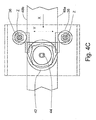
- FIGS. 4A to 4C the attached to the hand-held cleaning element, preferably in the form of a cup brush 42 shown.
- FIG. 4A is located in the front view of the hitch the cleaning element 42 on a shaft 44 with the central axis B of the hand machine 46th
- FIG. 4A is the cleaning element 42 between the rollers 36 above the recess 8 in the support plate. 2
- rollers 36 By arranging the rollers 36 with respect to the cup brush 42, preferably in the form of a cup brushed pot, it can be seen that with the embodiment of the invention by the arrangement of mounting device with base 1 and the rollers 36 and the cleaning element 42 between them a space H is created in which a in FIG. 4C shown elongate object 48 to be cleaned, preferably a formwork element, more preferably a frame element of a formwork, can be guided by the rollers 36, while a pointing to the cup brush 42 surface of the article 48 can be cleaned by the cup brush 42.
- a space H is created in which a in FIG. 4C shown elongate object 48 to be cleaned, preferably a formwork element, more preferably a frame element of a formwork, can be guided by the rollers 36, while a pointing to the cup brush 42 surface of the article 48 can be cleaned by the cup brush 42.
- a cover 40 which in the view from the front in FIG. 4A has the shape of a U-shaped profile, provided in such a way that in the direction perpendicular to the longitudinal direction X of the hand machine transverse direction Y, in which the rollers 36 are arranged side by side, wall portions 40a and 40b are provided, which is an emergence of the detached particles from Prevent the object 48 in the direction Y.
- a base section 40c of the cover 40 in which both a recess for the rotary shaft of the cleaning element and / or the cleaning elements, preferably in the form of the cup brush 42, as well as recesses for the threaded rods 28 are introduced.
- the cover 40 may be made of any material.
- a sheet preferably in the form of a center sheet with, for example, 3 mm thickness is preferred.
- this variant also has the advantage of a long service life.
- the object 48 to be cleaned is shown between the rollers 36, with the opposite side edges 48a and 48b not in abutment with both rollers 36 simultaneously.
- the distance of the rollers 36 may alternatively be chosen so that the object to be cleaned 48 is guided by both rollers simultaneously.
- the advantage here is a tighter fit.
- the contact pressure of the cleaning element on the surface to be cleaned can be made uniform only with great effort.
- the present invention is not limited to the configuration of the basic element.
- the basic element has the function, on the one hand to hold the hand machine and thus to allow attachment of the cleaning element to the hand machine, and on the other hand provide a support for guide elements on the object to be cleaned.
- These guide elements are in the illustrated embodiment rollers 36.
- these can be inventively arbitrarily designed as long as a guide of the base element is to be cleaned on the object.
- the invention is not limited to only one embodiment of the side fasteners 4 and 6.
- the recesses for introducing the threaded rods 28 may be formed in the side fastening elements 4 and 6 as slots, so that a different relative distance between the threaded rods for the rollers 36 is possible. In this way, with a basic element, the cleaning of a variety of different formwork elements, in particular frames, are made.
- a plurality of holes spaced transversely in the direction Y for receiving the threaded rods 28 may be provided in each side fastening element so that they can be arranged in different locations depending on the object to be cleaned.
- the invention is not limited to that, as in FIG. 4C shown in both the axial direction X and in the transverse direction Y, a distance between the central axis of the shaft 44 and the axes Z of the threaded rods 28 is present.
- the cleaning element 42 may be provided with its center axis B stronger between the rollers 36.
- the diameter of the brush is preferably in the range between 10 and 20 cm, more preferably in the range between 120 and 125 mm including the range limits.
- a plurality of commercially available frame elements can be cleaned by the cleaning element.
- the attachment can be applied after attachment to the hand machine and the application of the cleaning element on a formwork element to be cleaned, preferably the frame, and this can be moved with little effort by the rollers 36 along the frame. This ensures that the cleaning element is in every moment in contact with the object to be cleaned and due to the attached rollers 36 slipping of the cleaning element is prevented from the surface to be cleaned.
- the design of the hitch is also not limited to recesses in the side mounts for attachment to the hand machine.
- the base member preferably the side fasteners, may be configured in such a manner that a plurality of recesses may be provided to accommodate different ones Types of handheld machines or the side mountings may be slidably provided on the platen to accommodate different width dimensions of various hand machines.
- a mounting device for a hand machine via which a cleaning element on a hand machine, preferably on an electric hand machine, can be attached and on the guide during the cleaning process by guiding elements on the base element is possible.
- the guide elements are preferably rollers, which are more preferably arranged in pairs, so that a guide of the object to be cleaned is possible by manual operation certain cleaning intensity.
- a mounting device for a hand machine (46) is provided with a base element (1) which can be attached to the hand machine (46) between the hand machine (46) and a cleaning element (42) that can be moved relative to the base element (1) and can be driven by the hand machine, and at least one roller (36) rotatably mounted on the base element (1), on which an object (48) to be cleaned is movable at least on one side, while the object (48) to be cleaned at least in sections by the cleaning element movable relative to the base element (1) (42) is cleanable.
- a linear movement of the cleaning element relative to the base element (1) can be generated by the hand machine.
- the hand machine (46) has a rotary drive over which the cleaning element (42) is rotatable.
- the axis of rotation (Z) of the at least one roller (36) extends substantially parallel to the axis of rotation (B) of the cleaning element (42).
- the base element (1) has a support plate (2) for the hand machine and at least one side attachment (4; 6) for receiving the roller (36).
- the side mount (4; 6) and / or the platen (2) are made of structural steel.
- the platen (2) and the at least one side mount (4; 6) are joined together by welding.
- the roller (36) has a plastic coating.
- the roller (36) is attached to a side mount (4; 6) via a threaded rod (28).
- two rollers (36) fixed to the base member (1), between which the object to be cleaned (48) is passed, are provided at a predetermined distance (A).
- the object to be cleaned (48) is passable by the rollers (36) to its opposite side surface (48a, 48b) during cleaning.
- the object to be cleaned (48) is characterized by Rollers (36) during cleaning on its opposite side surface (48a, 48b) feasible.
- the rotation axis (B) of the cleaning member (42) is out of a plane defined by the rotation axes (Z) of the two rollers (36).
- the distance (A) between the two rollers (36) is changeable.
- At least one of the two rollers (36) is fixed in a slot in at least one of the side mounts of the base member (1).
- At least one of the side mounts of the base member (1) has at least two holes for receiving a reel (36) in two different positions.
- the geometric configuration of the base member (1) is adapted to the cleaning of frames of concrete formworks.
- a recess (24) for receiving a fastening means is provided in at least one side attachment (4; 6) of the base element (1), via which the hand machine (46) is attached to the base element (1 ) is rigidly attachable.
- a recess (24) is arranged in the base member (1) in such a manner that a fastening means for securing the latter is provided therein Base element (1) with respect to a receiving element of a handle for the hand machine (46) can be introduced.
- a cover (40) provided by the ejection of previously adhering to the object to be cleaned material Axial direction of the rotary drive of the hand machine (46) can be prevented.
- the cover (40) is U-shaped, so that ejection of material previously adhered to the object to be cleaned is perpendicular to the axial direction of the rotary drive and perpendicular to the direction of movement of the object to be cleaned (46). is preventable.
- the cover (40) is formed of Plexiglas or other translucent material.
- the cover (40) is formed of sheet metal, preferably center sheet, or other metallic material.
- the sheet is made of aluminum.
- the cleaning member (42) is a brush, preferably a cup brush.
- the cup brush (42) is plaited.
- the diameter of the cup brush (42) is larger than 10 cm and smaller than 20 cm.
- the hand machine (46) is an electric hand machine.
- the hand machine (46) is an angle grinder.
Landscapes
- Engineering & Computer Science (AREA)
- Architecture (AREA)
- Mechanical Engineering (AREA)
- Civil Engineering (AREA)
- Structural Engineering (AREA)
- Cleaning In General (AREA)
Applications Claiming Priority (1)
| Application Number | Priority Date | Filing Date | Title |
|---|---|---|---|
| DE102008057634A DE102008057634A1 (de) | 2008-11-17 | 2008-11-17 | Anbauvorrichtung für eine Handmaschine |
Publications (2)
| Publication Number | Publication Date |
|---|---|
| EP2186967A2 true EP2186967A2 (fr) | 2010-05-19 |
| EP2186967A3 EP2186967A3 (fr) | 2010-06-30 |
Family
ID=41800705
Family Applications (1)
| Application Number | Title | Priority Date | Filing Date |
|---|---|---|---|
| EP20090014359 Withdrawn EP2186967A3 (fr) | 2008-11-17 | 2009-11-17 | Dispositif de montage pour une machine manuelle |
Country Status (2)
| Country | Link |
|---|---|
| EP (1) | EP2186967A3 (fr) |
| DE (1) | DE102008057634A1 (fr) |
Cited By (1)
| Publication number | Priority date | Publication date | Assignee | Title |
|---|---|---|---|---|
| CN111502273A (zh) * | 2020-04-29 | 2020-08-07 | 汪煜 | 一种建筑钢模板表面处理工艺 |
Citations (3)
| Publication number | Priority date | Publication date | Assignee | Title |
|---|---|---|---|---|
| DE1759493A1 (de) | 1968-05-07 | 1971-07-08 | Josef Maier | Vorrichtung zum Reinigen und Aufbereiten von Schalungsteilen |
| DE3942784A1 (de) | 1989-12-23 | 1991-06-27 | Albert Haemmerle | Vorrichtung zur behandlung von rahmen, innenecken und passelemente von betonschalungen |
| DE202006011045U1 (de) | 2006-07-15 | 2006-11-16 | Franzer, Hans Werner | Gerät mit auswechselbaren Bürsten zum Reinigen von Oberflächen |
Family Cites Families (3)
| Publication number | Priority date | Publication date | Assignee | Title |
|---|---|---|---|---|
| DE1534924A1 (de) * | 1964-10-31 | 1969-09-11 | Festo Maschf Stoll G | Reinigungsvorrichtung zum Saeubern von Brettern,Platten,Tischen,Matrizen und Formstuecken,z.B. Schalungsplatten aus Holz,Stahlblech,Kunststoff usw.,von Ablagerungen,z.B. Moertel,- und Betonresten,anderen Schmutzteilchen,so auch Rost usw. |
| DE2036156A1 (de) * | 1970-07-21 | 1972-01-27 | Lorenz, Richard, 7571 Winden | Vorrichtung zur Reinigung von Schalungs teilen |
| JPS5815662A (ja) * | 1981-07-14 | 1983-01-29 | Hitachi Zosen Corp | 鋼板端部研摩装置 |
-
2008
- 2008-11-17 DE DE102008057634A patent/DE102008057634A1/de not_active Withdrawn
-
2009
- 2009-11-17 EP EP20090014359 patent/EP2186967A3/fr not_active Withdrawn
Patent Citations (3)
| Publication number | Priority date | Publication date | Assignee | Title |
|---|---|---|---|---|
| DE1759493A1 (de) | 1968-05-07 | 1971-07-08 | Josef Maier | Vorrichtung zum Reinigen und Aufbereiten von Schalungsteilen |
| DE3942784A1 (de) | 1989-12-23 | 1991-06-27 | Albert Haemmerle | Vorrichtung zur behandlung von rahmen, innenecken und passelemente von betonschalungen |
| DE202006011045U1 (de) | 2006-07-15 | 2006-11-16 | Franzer, Hans Werner | Gerät mit auswechselbaren Bürsten zum Reinigen von Oberflächen |
Cited By (1)
| Publication number | Priority date | Publication date | Assignee | Title |
|---|---|---|---|---|
| CN111502273A (zh) * | 2020-04-29 | 2020-08-07 | 汪煜 | 一种建筑钢模板表面处理工艺 |
Also Published As
| Publication number | Publication date |
|---|---|
| EP2186967A3 (fr) | 2010-06-30 |
| DE102008057634A1 (de) | 2010-05-20 |
Similar Documents
| Publication | Publication Date | Title |
|---|---|---|
| DE2818073C2 (de) | Tragbares Gerät zum Ablösen von auf einem Untergrund haftenden Bodenbelägen, Tapeten oder dergleichen | |
| DE2706187C3 (de) | Verfahren und Vorrichtung zum Herstellen einer Nut in einer bereits vorhandenen Wandfläche | |
| DE1427765B2 (de) | Führungseinrichtung für eine Betonschneidmaschine | |
| DE102011012739A1 (de) | Spanneinrichtung für Werkstücke aus Holz, Kunststoff und dergleichen | |
| DE3418689C1 (de) | Schneidwerkzeug zur Fugenraeumung bei Stahlbeton-Sanierung | |
| DE10042179A1 (de) | Führungseinrichtung für eine Kreissäge | |
| EP2186967A2 (fr) | Dispositif de montage pour une machine manuelle | |
| DE202004020654U1 (de) | Schwenkmaschine, insbesondere für Blechprofilmaterialien | |
| EP1562723B1 (fr) | Dispositif et procede d'usinage de pieces | |
| DE19700151A1 (de) | Verbesserung bei Vorrichtungen zum Entfernen von Windschutzscheiben | |
| DE202014100072U1 (de) | Bandschleifmaschine | |
| EP0787054A1 (fr) | Procede de decoupage d'un corps moule | |
| EP0219794B1 (fr) | Dispositif pour aplanir le crépi d'un mur | |
| DE29707996U1 (de) | Kratzputzmaschine mit Gehäuse und Handgriff | |
| EP2436489B1 (fr) | Unité de répartition de matériau | |
| DE29912524U1 (de) | Vorrichtung zum Reinigen von Oberflächen von Fahrzeugen, Behältern, Glas- oder Bodenflächen o.dgl., insbesondere von Personenkraftwagen | |
| DE2846238A1 (de) | Vorrichtung zum buersten von naturholzoberflaechen | |
| EP3664978B1 (fr) | Outil de coupe pour une machine-outil portative et machine-outil portative pourvue d'un outil de coupe | |
| DE20313062U1 (de) | Vorrichtung zum Lösen von Belägen | |
| DE102024117145A1 (de) | Selbstfahrende Reinigungsvorrichtung | |
| DE458636C (de) | Vorrichtung zum Riffeln ebener Flaechen von Bausteinen u. dgl. | |
| DE3402009A1 (de) | Arbeitsgeraet | |
| EP4688295A1 (fr) | Unité de lame et appareil de nettoyage pour éliminer les scories simultanément des côtés opposés d'une lamelle | |
| DE202015101725U1 (de) | Oszillationswerkzeug und Werkzeugmaschine zum Bearbeiten eines Werkstücks | |
| EP2851161B1 (fr) | Machine-outil portative et installation dotée d'une surface d'appui d'outil |
Legal Events
| Date | Code | Title | Description |
|---|---|---|---|
| PUAI | Public reference made under article 153(3) epc to a published international application that has entered the european phase |
Free format text: ORIGINAL CODE: 0009012 |
|
| AK | Designated contracting states |
Kind code of ref document: A2 Designated state(s): AT BE BG CH CY CZ DE DK EE ES FI FR GB GR HR HU IE IS IT LI LT LU LV MC MK MT NL NO PL PT RO SE SI SK SM TR |
|
| AX | Request for extension of the european patent |
Extension state: AL BA RS |
|
| PUAL | Search report despatched |
Free format text: ORIGINAL CODE: 0009013 |
|
| AK | Designated contracting states |
Kind code of ref document: A3 Designated state(s): AT BE BG CH CY CZ DE DK EE ES FI FR GB GR HR HU IE IS IT LI LT LU LV MC MK MT NL NO PL PT RO SE SI SK SM TR |
|
| AX | Request for extension of the european patent |
Extension state: AL BA RS |
|
| RIC1 | Information provided on ipc code assigned before grant |
Ipc: B24B 27/033 20060101ALI20100521BHEP Ipc: B24B 23/00 20060101ALI20100521BHEP Ipc: B08B 1/04 20060101ALI20100521BHEP Ipc: B24B 23/02 20060101ALI20100521BHEP Ipc: E04G 19/00 20060101AFI20100317BHEP |
|
| 17P | Request for examination filed |
Effective date: 20101229 |
|
| 17Q | First examination report despatched |
Effective date: 20120724 |
|
| STAA | Information on the status of an ep patent application or granted ep patent |
Free format text: STATUS: THE APPLICATION IS DEEMED TO BE WITHDRAWN |
|
| 18D | Application deemed to be withdrawn |
Effective date: 20150730 |