EP2187009B1 - Procédé de fonctionnement d'un système de traitement des gaz d'échappement - Google Patents
Procédé de fonctionnement d'un système de traitement des gaz d'échappement Download PDFInfo
- Publication number
- EP2187009B1 EP2187009B1 EP09171096A EP09171096A EP2187009B1 EP 2187009 B1 EP2187009 B1 EP 2187009B1 EP 09171096 A EP09171096 A EP 09171096A EP 09171096 A EP09171096 A EP 09171096A EP 2187009 B1 EP2187009 B1 EP 2187009B1
- Authority
- EP
- European Patent Office
- Prior art keywords
- dosing
- exhaust gas
- reductant
- control
- ammonia
- Prior art date
- Legal status (The legal status is an assumption and is not a legal conclusion. Google has not performed a legal analysis and makes no representation as to the accuracy of the status listed.)
- Active
Links
Images


Classifications
-
- F—MECHANICAL ENGINEERING; LIGHTING; HEATING; WEAPONS; BLASTING
- F01—MACHINES OR ENGINES IN GENERAL; ENGINE PLANTS IN GENERAL; STEAM ENGINES
- F01N—GAS-FLOW SILENCERS OR EXHAUST APPARATUS FOR MACHINES OR ENGINES IN GENERAL; GAS-FLOW SILENCERS OR EXHAUST APPARATUS FOR INTERNAL-COMBUSTION ENGINES
- F01N3/00—Exhaust or silencing apparatus having means for purifying, rendering innocuous, or otherwise treating exhaust
- F01N3/08—Exhaust or silencing apparatus having means for purifying, rendering innocuous, or otherwise treating exhaust for rendering innocuous
- F01N3/10—Exhaust or silencing apparatus having means for purifying, rendering innocuous, or otherwise treating exhaust for rendering innocuous by thermal or catalytic conversion of noxious components of exhaust
- F01N3/18—Exhaust or silencing apparatus having means for purifying, rendering innocuous, or otherwise treating exhaust for rendering innocuous by thermal or catalytic conversion of noxious components of exhaust characterised by methods of operation; Control
- F01N3/20—Exhaust or silencing apparatus having means for purifying, rendering innocuous, or otherwise treating exhaust for rendering innocuous by thermal or catalytic conversion of noxious components of exhaust characterised by methods of operation; Control specially adapted for catalytic conversion
- F01N3/206—Adding periodically or continuously substances to exhaust gases for promoting purification, e.g. catalytic material in liquid form, NOx reducing agents
- F01N3/208—Control of selective catalytic reduction [SCR], e.g. by adjusting the dosing of reducing agent
-
- F—MECHANICAL ENGINEERING; LIGHTING; HEATING; WEAPONS; BLASTING
- F01—MACHINES OR ENGINES IN GENERAL; ENGINE PLANTS IN GENERAL; STEAM ENGINES
- F01N—GAS-FLOW SILENCERS OR EXHAUST APPARATUS FOR MACHINES OR ENGINES IN GENERAL; GAS-FLOW SILENCERS OR EXHAUST APPARATUS FOR INTERNAL-COMBUSTION ENGINES
- F01N13/00—Exhaust or silencing apparatus characterised by constructional features
- F01N13/009—Exhaust or silencing apparatus characterised by constructional features having two or more separate purifying devices arranged in series
- F01N13/0093—Exhaust or silencing apparatus characterised by constructional features having two or more separate purifying devices arranged in series the purifying devices are of the same type
-
- F—MECHANICAL ENGINEERING; LIGHTING; HEATING; WEAPONS; BLASTING
- F01—MACHINES OR ENGINES IN GENERAL; ENGINE PLANTS IN GENERAL; STEAM ENGINES
- F01N—GAS-FLOW SILENCERS OR EXHAUST APPARATUS FOR MACHINES OR ENGINES IN GENERAL; GAS-FLOW SILENCERS OR EXHAUST APPARATUS FOR INTERNAL-COMBUSTION ENGINES
- F01N9/00—Electrical control of exhaust gas treating apparatus
-
- F—MECHANICAL ENGINEERING; LIGHTING; HEATING; WEAPONS; BLASTING
- F01—MACHINES OR ENGINES IN GENERAL; ENGINE PLANTS IN GENERAL; STEAM ENGINES
- F01N—GAS-FLOW SILENCERS OR EXHAUST APPARATUS FOR MACHINES OR ENGINES IN GENERAL; GAS-FLOW SILENCERS OR EXHAUST APPARATUS FOR INTERNAL-COMBUSTION ENGINES
- F01N2560/00—Exhaust systems with means for detecting or measuring exhaust gas components or characteristics
- F01N2560/02—Exhaust systems with means for detecting or measuring exhaust gas components or characteristics the means being an exhaust gas sensor
- F01N2560/021—Exhaust systems with means for detecting or measuring exhaust gas components or characteristics the means being an exhaust gas sensor for measuring or detecting ammonia NH3
-
- F—MECHANICAL ENGINEERING; LIGHTING; HEATING; WEAPONS; BLASTING
- F01—MACHINES OR ENGINES IN GENERAL; ENGINE PLANTS IN GENERAL; STEAM ENGINES
- F01N—GAS-FLOW SILENCERS OR EXHAUST APPARATUS FOR MACHINES OR ENGINES IN GENERAL; GAS-FLOW SILENCERS OR EXHAUST APPARATUS FOR INTERNAL-COMBUSTION ENGINES
- F01N2560/00—Exhaust systems with means for detecting or measuring exhaust gas components or characteristics
- F01N2560/02—Exhaust systems with means for detecting or measuring exhaust gas components or characteristics the means being an exhaust gas sensor
- F01N2560/026—Exhaust systems with means for detecting or measuring exhaust gas components or characteristics the means being an exhaust gas sensor for measuring or detecting NOx
-
- F—MECHANICAL ENGINEERING; LIGHTING; HEATING; WEAPONS; BLASTING
- F01—MACHINES OR ENGINES IN GENERAL; ENGINE PLANTS IN GENERAL; STEAM ENGINES
- F01N—GAS-FLOW SILENCERS OR EXHAUST APPARATUS FOR MACHINES OR ENGINES IN GENERAL; GAS-FLOW SILENCERS OR EXHAUST APPARATUS FOR INTERNAL-COMBUSTION ENGINES
- F01N2560/00—Exhaust systems with means for detecting or measuring exhaust gas components or characteristics
- F01N2560/06—Exhaust systems with means for detecting or measuring exhaust gas components or characteristics the means being a temperature sensor
-
- F—MECHANICAL ENGINEERING; LIGHTING; HEATING; WEAPONS; BLASTING
- F01—MACHINES OR ENGINES IN GENERAL; ENGINE PLANTS IN GENERAL; STEAM ENGINES
- F01N—GAS-FLOW SILENCERS OR EXHAUST APPARATUS FOR MACHINES OR ENGINES IN GENERAL; GAS-FLOW SILENCERS OR EXHAUST APPARATUS FOR INTERNAL-COMBUSTION ENGINES
- F01N2560/00—Exhaust systems with means for detecting or measuring exhaust gas components or characteristics
- F01N2560/08—Exhaust systems with means for detecting or measuring exhaust gas components or characteristics the means being a pressure sensor
-
- F—MECHANICAL ENGINEERING; LIGHTING; HEATING; WEAPONS; BLASTING
- F01—MACHINES OR ENGINES IN GENERAL; ENGINE PLANTS IN GENERAL; STEAM ENGINES
- F01N—GAS-FLOW SILENCERS OR EXHAUST APPARATUS FOR MACHINES OR ENGINES IN GENERAL; GAS-FLOW SILENCERS OR EXHAUST APPARATUS FOR INTERNAL-COMBUSTION ENGINES
- F01N2560/00—Exhaust systems with means for detecting or measuring exhaust gas components or characteristics
- F01N2560/14—Exhaust systems with means for detecting or measuring exhaust gas components or characteristics having more than one sensor of one kind
-
- F—MECHANICAL ENGINEERING; LIGHTING; HEATING; WEAPONS; BLASTING
- F01—MACHINES OR ENGINES IN GENERAL; ENGINE PLANTS IN GENERAL; STEAM ENGINES
- F01N—GAS-FLOW SILENCERS OR EXHAUST APPARATUS FOR MACHINES OR ENGINES IN GENERAL; GAS-FLOW SILENCERS OR EXHAUST APPARATUS FOR INTERNAL-COMBUSTION ENGINES
- F01N2570/00—Exhaust treating apparatus eliminating, absorbing or adsorbing specific elements or compounds
- F01N2570/18—Ammonia
-
- F—MECHANICAL ENGINEERING; LIGHTING; HEATING; WEAPONS; BLASTING
- F01—MACHINES OR ENGINES IN GENERAL; ENGINE PLANTS IN GENERAL; STEAM ENGINES
- F01N—GAS-FLOW SILENCERS OR EXHAUST APPARATUS FOR MACHINES OR ENGINES IN GENERAL; GAS-FLOW SILENCERS OR EXHAUST APPARATUS FOR INTERNAL-COMBUSTION ENGINES
- F01N2610/00—Adding substances to exhaust gases
- F01N2610/02—Adding substances to exhaust gases the substance being ammonia or urea
-
- F—MECHANICAL ENGINEERING; LIGHTING; HEATING; WEAPONS; BLASTING
- F01—MACHINES OR ENGINES IN GENERAL; ENGINE PLANTS IN GENERAL; STEAM ENGINES
- F01N—GAS-FLOW SILENCERS OR EXHAUST APPARATUS FOR MACHINES OR ENGINES IN GENERAL; GAS-FLOW SILENCERS OR EXHAUST APPARATUS FOR INTERNAL-COMBUSTION ENGINES
- F01N2610/00—Adding substances to exhaust gases
- F01N2610/14—Arrangements for the supply of substances, e.g. conduits
- F01N2610/1453—Sprayers or atomisers; Arrangement thereof in the exhaust apparatus
- F01N2610/146—Control thereof, e.g. control of injectors or injection valves
-
- F—MECHANICAL ENGINEERING; LIGHTING; HEATING; WEAPONS; BLASTING
- F01—MACHINES OR ENGINES IN GENERAL; ENGINE PLANTS IN GENERAL; STEAM ENGINES
- F01N—GAS-FLOW SILENCERS OR EXHAUST APPARATUS FOR MACHINES OR ENGINES IN GENERAL; GAS-FLOW SILENCERS OR EXHAUST APPARATUS FOR INTERNAL-COMBUSTION ENGINES
- F01N2900/00—Details of electrical control or of the monitoring of the exhaust gas treating apparatus
- F01N2900/04—Methods of control or diagnosing
- F01N2900/0402—Methods of control or diagnosing using adaptive learning
-
- F—MECHANICAL ENGINEERING; LIGHTING; HEATING; WEAPONS; BLASTING
- F01—MACHINES OR ENGINES IN GENERAL; ENGINE PLANTS IN GENERAL; STEAM ENGINES
- F01N—GAS-FLOW SILENCERS OR EXHAUST APPARATUS FOR MACHINES OR ENGINES IN GENERAL; GAS-FLOW SILENCERS OR EXHAUST APPARATUS FOR INTERNAL-COMBUSTION ENGINES
- F01N2900/00—Details of electrical control or of the monitoring of the exhaust gas treating apparatus
- F01N2900/04—Methods of control or diagnosing
- F01N2900/0408—Methods of control or diagnosing using a feed-back loop
-
- F—MECHANICAL ENGINEERING; LIGHTING; HEATING; WEAPONS; BLASTING
- F01—MACHINES OR ENGINES IN GENERAL; ENGINE PLANTS IN GENERAL; STEAM ENGINES
- F01N—GAS-FLOW SILENCERS OR EXHAUST APPARATUS FOR MACHINES OR ENGINES IN GENERAL; GAS-FLOW SILENCERS OR EXHAUST APPARATUS FOR INTERNAL-COMBUSTION ENGINES
- F01N2900/00—Details of electrical control or of the monitoring of the exhaust gas treating apparatus
- F01N2900/04—Methods of control or diagnosing
- F01N2900/0412—Methods of control or diagnosing using pre-calibrated maps, tables or charts
-
- F—MECHANICAL ENGINEERING; LIGHTING; HEATING; WEAPONS; BLASTING
- F01—MACHINES OR ENGINES IN GENERAL; ENGINE PLANTS IN GENERAL; STEAM ENGINES
- F01N—GAS-FLOW SILENCERS OR EXHAUST APPARATUS FOR MACHINES OR ENGINES IN GENERAL; GAS-FLOW SILENCERS OR EXHAUST APPARATUS FOR INTERNAL-COMBUSTION ENGINES
- F01N2900/00—Details of electrical control or of the monitoring of the exhaust gas treating apparatus
- F01N2900/06—Parameters used for exhaust control or diagnosing
- F01N2900/14—Parameters used for exhaust control or diagnosing said parameters being related to the exhaust gas
-
- F—MECHANICAL ENGINEERING; LIGHTING; HEATING; WEAPONS; BLASTING
- F01—MACHINES OR ENGINES IN GENERAL; ENGINE PLANTS IN GENERAL; STEAM ENGINES
- F01N—GAS-FLOW SILENCERS OR EXHAUST APPARATUS FOR MACHINES OR ENGINES IN GENERAL; GAS-FLOW SILENCERS OR EXHAUST APPARATUS FOR INTERNAL-COMBUSTION ENGINES
- F01N2900/00—Details of electrical control or of the monitoring of the exhaust gas treating apparatus
- F01N2900/06—Parameters used for exhaust control or diagnosing
- F01N2900/18—Parameters used for exhaust control or diagnosing said parameters being related to the system for adding a substance into the exhaust
- F01N2900/1806—Properties of reducing agent or dosing system
-
- Y—GENERAL TAGGING OF NEW TECHNOLOGICAL DEVELOPMENTS; GENERAL TAGGING OF CROSS-SECTIONAL TECHNOLOGIES SPANNING OVER SEVERAL SECTIONS OF THE IPC; TECHNICAL SUBJECTS COVERED BY FORMER USPC CROSS-REFERENCE ART COLLECTIONS [XRACs] AND DIGESTS
- Y02—TECHNOLOGIES OR APPLICATIONS FOR MITIGATION OR ADAPTATION AGAINST CLIMATE CHANGE
- Y02T—CLIMATE CHANGE MITIGATION TECHNOLOGIES RELATED TO TRANSPORTATION
- Y02T10/00—Road transport of goods or passengers
- Y02T10/10—Internal combustion engine [ICE] based vehicles
- Y02T10/12—Improving ICE efficiencies
-
- Y—GENERAL TAGGING OF NEW TECHNOLOGICAL DEVELOPMENTS; GENERAL TAGGING OF CROSS-SECTIONAL TECHNOLOGIES SPANNING OVER SEVERAL SECTIONS OF THE IPC; TECHNICAL SUBJECTS COVERED BY FORMER USPC CROSS-REFERENCE ART COLLECTIONS [XRACs] AND DIGESTS
- Y02—TECHNOLOGIES OR APPLICATIONS FOR MITIGATION OR ADAPTATION AGAINST CLIMATE CHANGE
- Y02T—CLIMATE CHANGE MITIGATION TECHNOLOGIES RELATED TO TRANSPORTATION
- Y02T10/00—Road transport of goods or passengers
- Y02T10/10—Internal combustion engine [ICE] based vehicles
- Y02T10/40—Engine management systems
Definitions
- the relevant background includes the fields of exhaust gas treatment systems and diagnostics therefore.
- a SCR catalyst treatment device that includes a catalyst and a system that is operable to inject material such as ammonia (NH 3 ) into the exhaust gas feedstream ahead of the catalyst.
- the SCR catalyst is constructed so as to promote the reduction of NOx by NH 3 (or other reductant, such as aqueous urea which undergoes decomposition in the exhaust to produce NH 3 ).
- diagnostics The intent of such diagnostics is to inform the operator when performance of a component and/or system has degraded to a level where emissions performance may be affected and to provide information ( e.g ., via the DTC) to facilitate remediation. an adequate solution. It would be advantageous to provide diagnostic routines to detect any such degradation.
- the invention provides an advantage for exhaust gas treatment systems that use ammonia or other reductant (e.g ., aqueous urea solution) injection in combination with an SCR catalyst for NOx removal from the engine exhaust gas. More specifically, the invention allows for an increased default dosing rate for normal operation, particularly at lower temperatures (e.g ., below 300 °C), for maximal NOx conversion under certain driving conditions, without significant risk of high ammonia concentration slips when the temperature increases. This is because the control features of the invention are configured to recognize when possible ammonia slips are likely and reduce the dosing in advance.
- ammonia or other reductant e.g ., aqueous urea solution
- a method of NH 3 slip control is provided.
- the slip control feature in one embodiments, shuts-off dosing when certain exhaust conditions are detected, thereby mitigating an ammonia slip.
- the method includes a number of steps. The first step involves dosing reductant (e.g ., NH 3 , aqueous urea) into the exhaust gas stream. Next, establishing an ammonia slip trip level based on the exhaust temperature. Finally, decreasing (perhaps significantly), and preferably, discontinuing, the dosing step when an ammonia concentration level, measured at the SCR catalyst ( e.g ., mid-brick position) exceeds the ammonia slip trip level, provided that the exhaust temperature gradient is in an increasing state.
- the combination of conditions indicate the risk of an unacceptably high NH 3 slip and warrant shutting-off dosing until the conditions subside.
- An exhaust gas treatment system is also presented.
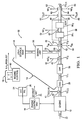
- FIG. 1 is a diagrammatic and block diagram showing an exhaust treatment system in which the control methods of the invention may be practiced.
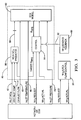
- Figure 2 is a block diagram showing an overview of the dosing control that includes an SCR model as well as improved control features.
- Figure 3 is a signal flow mechanization schematic showing inputs and outputs of the SCR model.
- Figure 4 is a simplified diagram showing typical target theta ( ⁇ ) values or curves as a function of temperature.
- Figure 5 is a flowchart of a method for controlling an exhaust treatment system involving ammonia (NH 3 ) slip control.
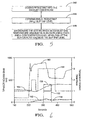
- Figure 7 is a timing diagram showing NOx removal and exhaust temperature.
- embodiments of the invention may be used in heavy-duty applications (e.g ., highway tractors, trucks and the like) as well as light-duty applications (e.g ., passenger cars).
- embodiments of the invention may find further useful application in various types of internal combustion engines, such as compression-ignition (e.g ., diesel) engines as well as spark-ignition engines.
- the engine 10 may be a turbocharged diesel engine.
- the engine 10 comprised a conventional 6.6-liter, 8-cylinder turbocharged diesel engine commercially available under the DuraMax trade designation. It should be understood this is exemplary only.
- FIG. 1 also shows an engine control unit (ECU) 16 configured to control the operation of the engine 10.
- the ECU 16 may comprise conventional apparatus known generally in the art for such purpose.
- the ECU 16 may include at least one microprocessor or other processing unit, associated memory devices such as read only memory (ROM) and random access memory (RAM), a timing clock, input devices for monitoring input from external analog and digital devices and controlling output devices.
- the ECU 16 is operable to monitor engine operating conditions and other inputs (e.g ., operator inputs) using the plurality of sensors and input mechanisms, and control engine operations with the plurality of output systems and actuators, using pre-established algorithms and calibrations that integrate information from monitored conditions and inputs. It should be understood that many of the conventional sensors employed in an engine system have been omitted for clarity.
- the ECU 16 may be configured to calculate an exhaust mass air flow (MAF) parameter 20 indicative of the mass air flow exiting engine 10.
- MAF exhaust mass air flow
- the software algorithms and calibrations which are executed in the ECU 16 may generally comprise conventional strategies known to those of ordinary skill in the art. Overall, in response to the various inputs, the ECU 16 develops the necessary outputs to control the throttle valve position, fueling (fuel injector opening, duration and closing), spark (ignition timing) and other aspects, all as known in the art.
- the ECU 16 is also typically configured to perform various diagnostics.
- the ECU 16 may be configured to include a diagnostic data manager or the like, a higher level service arranged to manage the reports received from various lower level diagnostic routines/circuits, and set or reset diagnostic trouble code(s)/service codes, as well as activate or extinguish various alerts, all as known generally in the art.
- a diagnostic data manager may be pre-configured such that certain non-continuous monitoring diagnostics require that such diagnostic fail twice before a diagnostic trouble code (DTC) is set and a malfunction indicator lamp (MIL) is illuminated.
- DTC diagnostic trouble code
- MIL malfunction indicator lamp
- the ECU 16 may be configured to set a corresponding diagnostic trouble code (DTC) 24 and/or generate an operator alert, such an illumination of a MIL 26.
- DTC diagnostic trouble code
- the ECU 16 may be configured so as to allow interrogation (e.g ., by a skilled technician) for retrieval of such set DTCs.
- interrogation e.g ., by a skilled technician
- the process of storing diagnostic trouble codes and subsequent interrogation and retrieval is well known to one skilled in the art and will not be described in any further detailed.
- a DOC inlet temperature sensor 39 configured to generate a DOC inlet temperature signal 41 (T DOC-IN ), a NOx sensor 40 configured to generate a NOx signal 42 (NOx) indicative of a sensed NOx concentration, a first exhaust gas temperature sensor 44, located at the inlet of the SCR catalyst 38, configured to generate a first temperature signal 46 (T IN ), an optional second exhaust gas temperature sensor 48 configured to generate a second temperature signal 50 (T OUT ), a first pressure sensor 52 configured to generate a first pressure signal 54 (PIN), a second pressure sensor 56 configured to generate a second pressure signal 58 (P OUT ), and an ammonia (NH 3 ) concentration sensor 60 configured to generate an ammonia concentration signal 62 indicative of the sensed NH 3 concentration.
- a NOx sensor 64 is provided for generating a second NOx signal 66 indicative of the NOx concentration exiting the tail pipe. However, such is shown for completeness only.
- the DOC 28 and the DPF 30 may comprise conventional components to perform their known functions.
- the dosing subsystem 32 is responsive to an NH 3 Request signal produced by a dosing control 80 and configured to deliver a NOx reducing agent at an injection node 68, which is introduced in the exhaust gas stream in accurate, controlled doses 70 ( e.g ., mass per unit time).
- the reducing agent may be, in general, (1) NH 3 gas or (2) a urea-water solution containing a predetermined known concentration of urea.
- the SCR catalyst 38 is configured to provide a mechanism to promote a selective reduction reaction between NOx, on the one hand, and a reductant such as ammonia gas NH 3 (or aqueous urea, which decomposes into ammonia, NH 3 ) on the other hand.
- a reductant such as ammonia gas NH 3 (or aqueous urea, which decomposes into ammonia, NH 3 ) on the other hand.
- a reductant such as ammonia gas NH 3 (or aqueous urea, which decomposes into ammonia, NH 3 ) on the other hand.
- a reductant such as ammonia gas NH 3 (or aqueous urea, which decomposes into ammonia, NH 3 ) on the other hand.
- the SCR catalyst 38 may comprise copper zeolite (Cu-zeolite) material, although other materials are known. See, for example, U.S. Patent No.
- the SCR catalyst 38 may be of multi-brick construction, including a plurality of individual bricks 38 1 , 38 2 wherein each "brick” may be substantially disc-shaped.
- the "bricks” may be housed in a suitable enclosure, as known.
- the NOx concentration sensor 40 is located upstream of the injection node 68.
- the NOx sensor 40 is so located so as to avoid possible interference in the NOx sensing function due to the presence of NH 3 gas.
- the NOx sensor 40 may alternatively be located further upstream, between the DOC 28 and the DPF 30, or upstream of the DOC 28.
- the exhaust temperature is often referred to herein, and for such purpose, the temperature reading from the SCR inlet temperature sensor 44 (T IN ) may be used.
- the NH 3 sensor 60 may be located, in certain embodiments, at a mid-brick position, as shown in solid line ( i.e ., located anywhere downstream of the inlet of the SCR catalyst 38 and upstream of the outlet of the SCR catalyst 38). As illustrated, the NH 3 sensor 60 may be located at approximately the center position. The mid-brick positioning is significant. The sensed ammonia concentration level in this arrangement, even during nominal operation, is at a small yet detectable level of mid-brick NH 3 slip, where the downstream NOx conversion with this detectable NH 3 can be assumed in the presence of the rear brick, even further reducing NH 3 concentration levels at the tail pipe to within acceptable levels. Alternatively, in certain embodiments, the NH 3 sensor 60 may be located at the outlet of the SCR catalyst 38. The remainder of the sensors shown in Figure 1 may comprise conventional components and be configured to perform in a conventional manner known to those of ordinary skill in the art.
- the dosing control 80 is configured to generate the NH 3 Request signal that is sent to the dosing unit 36, which represents the command for a specified amount (e.g ., mass rate) of reductant to be delivered to the exhaust gas stream.
- the dosing control 80 includes a plurality of inputs and outputs, designated 18, for interface with various sensors, other control units, etc., as described herein.
- the dosing control 80 is shown as a separate block, it should be understood that depending on the particular arrangement, the functionality of the dosing control 80 may be implemented in a separate controller, incorporated into the ECU 16, or incorporated, in whole or in part, in other control units already existing in the system (e.g ., the dosing unit).
- the dosing control 80 may be configured to perform not only control functions described herein but perform the various diagnostics also described herein as well.
- the dosing control 80 may include conventional processing apparatus known in the art, capable of executing pre-programmed instructions stored in an associated memory, all performing in accordance with the functionality described herein. That is, it is contemplated that the control and diagnostic processes described herein will be programmed in a preferred embodiment, with the resulting software code being stored in the associated memory. Implementation of the invention, in software, in view of the foregoing enabling description, would require no more than routine application of programming skills by one of ordinary skill in the art.
- Such a control may further be of the type having both ROM, RAM, a combination of non-volatile and volatile (modifiable) memory so that the software can be stored and yet allow storage and processing of dynamically produced data and/or signals.
- FIG 2 is a block diagram showing an overview of the dosing control 80 of Figure 1 .
- the basic strategy is to control the dosing rate (e.g ., urea-water solution) so as to ensure that the there is adequate ammonia stored in the SCR catalyst 38 to achieve (i) a high NOx conversion rate ( i.e ., conversion of NOx into N 2 and H 2 O), with (ii) a low occurrence or no occurrence at all of ammonia (NH 3 ) slips exceeding predetermined maximum thresholds.
- the dosing rate e.g ., urea-water solution
- a high NOx conversion rate i.e ., conversion of NOx into N 2 and H 2 O
- NH 3 ammonia
- the dosing control 80 is configured to generate an NH 3 Request, which is communicated to the dosing unit 36 (i.e ., shown as the "NH 3 /Urea Dosing").
- the NH 3 Request is indicative of the mass flow rate at which the dosing subsystem 32 is to introduce the urea-water solution into the exhaust gas stream.
- the control variable used in implementing the dosing control strategy is a so-called ammonia surface coverage parameter theta ( ⁇ NH3 ), which corresponds to the NH 3 surface storage fraction associated with the SCR catalyst 38.
- the ammonia surface coverage parameter theta ( ⁇ NH3 ) indicates the amount of ammonia-NH 3 stored in the SCR catalyst 38.
- One aspect of the operation of the dosing control 80 involves an SCR model 82.
- FIG 3 is a signal flow mechanization schematic showing inputs and outputs of the SCR model 82.
- the SCR model 82 is a chemistry-based SCR model and is shown with a theta control block 84, and a "NO and NO 2 " predictor block 86.
- the SCR model 82 is configured to model the physical SCR catalyst 38 and compute real time values for the ammonia surface coverage parameter theta ( ⁇ NH3 ).
- the theta control block 84 is configured to compare the computed theta ( ⁇ NH3 ) against a target value for theta ("Target ⁇ NH3 "), which results in a theta error.
- the theta control block 84 is configured to use a control strategy (e.g ., a proportional-integral (PI) control algorithm) to adjust the requested NH 3 dosing rate ("NH 3 Request") to reduce the theta error.
- a control strategy e.g ., a proportional-integral (PI) control algorithm
- the theta control block 84 also employs closed-loop feedback, being responsive to ammonia sensing feedback by way of the ammonia sensor 60.
- the theta control block 84 may use NH 3 feedback generally to adapt target theta values to account for catalyst degradation, urea injection malfunction or dosing fluid concentration variation that may be encountered during real-world use.
- the NH 3 sensing feedback is also used for various control and diagnostic improvements.
- the predictor block 86 receives the DOC inlet temperature signal 41 (T DOC-IN ), the NOx sensor signal 42 and the exhaust flow signal 90 as inputs and is configured to produce data 88 indicative of the respective NO and NO 2 concentration levels (engine out) produced by the engine 10.
- the predictor block 86 may comprise a look-up table (LUT) containing NO and NO 2 data experimentally measured from the engine 10.
- the SCR model 82 may be configured to have access to a plurality of signals/parameters as needed to execute the predetermined calculations needed to model the catalyst 38.
- this access to sensor outputs and other data sources may be implemented over a vehicle network (not shown), but which may be a controller area network (CAN) for certain vehicle embodiments.
- CAN controller area network
- access to certain information may be direct to the extent that the dosing control 80 is integrated with the engine control function in the ECU 16. It should be understood that other variations are possible.
- the SCR model 82 may comprise conventional models known in the art for modeling an SCR catalyst.
- the SCR model 82 is responsive to a number of inputs, including: (i) predicted NO and NO 2 levels 88; (ii) an inlet NOx amount, which may be derived from the NOx indicative signal 42 (best shown in Figure 1 ); (iii) an exhaust mass air flow (MAF) amount 90, which may be either a measured value or a value computed by the ECU 16 and shown as exhaust MAF parameter 20 in Figure 1 ; (iv) an SCR inlet temperature, which may be derived from the first temperature signal 46 (T IN ); (v) an SCR inlet pressure, which may be derived from the first pressure signal 54 (P IN ); and (vi) the actual amount of reductant (e.g ., NH 3 , urea-water solution shown as "NH 3 Actual” in Figure 2 ) introduced by the dosing subsystem 32.
- reductant e.g ., NH 3 , ure
- values for theta ( ⁇ NH3 ) are updated at a frequency of 10 Hz, although it should be understood this rate is exemplary only.
- ⁇ NH3 surface coverage parameter
- the dosing control 80 includes additional blocks.
- a target theta parameter (Target ⁇ NH3 ) block 92 is shown, which is configured to provide a value for the target theta parameter (Target ⁇ NH3 ) preferably as function of temperature (e.g ., exhaust gas temperature, such as the SCR inlet temperature T IN ).
- the target ⁇ NH3 which is determined as a function of the SCR catalyst inlet temperature T IN , is conventionally set-up based on the following considerations: (1) desire to achieve a maximum possible NOx conversion efficiency with acceptable NH 3 slip levels (30 ppm peak, 10 ppm average) for a given emission test cycle, and (2) recognition that limits must be set for the theta values at low temperatures to prevent potential high NH 3 slips upon sudden temperature ramp up in off-cycle tests.
- a pure ammonia storage control mode i.e ., theta parameter control
- different emission cycles may call for different theta values in order to achieve the best NOx conversion within the confines of the applicable NH 3 slip limits.
- Figure 4 is a diagram showing exemplary target theta ⁇ NH3 curves determined for both the Euro Stationary Cycle (ESC) and the Federal Test Procedure (FTP) emission cycles using Cu-zeolite catalysts.
- ESC Euro Stationary Cycle
- FTP Federal Test Procedure
- the values from one of the target theta curves may be stored in a look-up table (LUT) or the like for run-time use by the theta control block 84 of the dosing control 80.
- Such values may take the form of (temperature, theta value) data pairs.
- the theta control 84 further includes a comparator 94 (e.g., a summer, or equivalent) configured to generate the theta error signal described above, indicative of the difference between the target theta (Target ⁇ NH3 ) and the computed theta ( ⁇ NH3 ) from the SCR model.
- a PI control 96 is configured to produce an output signal configured to reduce the magnitude of the theta error.
- a high level control block 98 is responsive to various inputs to produce the NH 3 Request signal, which is communicated to the dosing subsystem 32.
- Figure 2 also shows, in block form, a number of additional control and diagnostic features. These additional control and diagnostic features may be arranged to work together in some embodiments to achieve maximum NOx conversion while maintaining acceptable NH 3 slip levels under various driving conditions ( i.e ., in vehicle applications).
- the dosing control 80 thus includes a number of functional blocks to implement these features: a theta perturbation diagnostic block 100, an adaptive learning diagnostic block 102, a transient compensation control block 104 and an NH 3 slip control block 106.
- the theta perturbation diagnostic block 100 is configured to perturb the target theta parameter in accordance with a small diagnostic function and to measure the resulting response to determine the state of health of one or more components of the exhaust treatment system 14.
- the adaptive learning diagnostic block 102 includes a diagnostic feature that monitors how much adaptation has been applied in adjusting the target theta parameter and generates an error when the level of adaptation exceeds predetermined upper and lower limits.
- the logic in operation is that at some level, the ability to adapt target theta values to overcome errors (e.g ., reagent misdosing, reagent quality problems, SCR catalyst degradation) will reach its control limit for maintaining emissions. When this control limit is exceeded, the diagnostic generates an error.
- the improvement involves shutting-off dosing altogether when certain exhaust conditions are recognized by the dosing control ("NH 3 slip control").
- This aspect of the invention addresses the NH 3 slip risk during SCR catalyst operation while maximizing NOx conversion efficiency by using a mid-brick positioned ammonia sensor to provide feedback for detecting the slip risk.
- the ammonia sensor being located at a mid-brick position of the SCR catalyst provides greater sensitivity to NH 3 dosing variation because of reduced NH 3 storage capacity of the front ( i.e ., forward or upstream) brick ( e.g ., see Figure 8 below). Therefore, the more rapid response to dosing errors, by virtue of the mid-brick detection, can be utilized to control ammonia slip with the help of the back ( i.e ., rear or downstream) brick.
- This feature of the invention utilizes this quick response in combination with the recognition of certain exhaust conditions to activate a slip trip mode, which calls for, in one embodiment, complete dosing shut-off. This feature provides even greater flexibility in ammonia slip control while maximizing NOx removal.
- step 142 the method involves dosing NH 3 (i.e ., a reductant, generally, such as urea-water solution of Figure 1 ) into the exhaust stream in an amount based on target theta (target ⁇ NH3 ).
- a reductant generally, such as urea-water solution of Figure 1
- target theta target ⁇ NH3
- This feature may remain inactive until a predetermined, minimum temperature has been reached, which may range between about 250 to 300 °C may further be between about 275 to 300 °C and may be about 300 °C.
- the compromises of a fixed target theta curve may manifest themselves more acutely as the catalyst temperature increases rapidly, particularly the low end of the overall target theta table where ammonia storage is high but where there is more risk of NH 3 slip. Therefore, it should be understood that while the NH 3 slip control feature will be most useful in those certain temperature ranges, the invention is not so limited.
- the ammonia concentration sensor 60 is preferably located for this method at a mid-brick position. The sensor 60 produces an ammonia concentration signal 62 that is indicative of the ammonia concentration level.
- Figure 6 shows the ammonia concentration level as trace 148. The method proceeds to step 144.
- an NH 3 slip trip level is established (e.g ., 50 ppm).
- the slip trip level may be adjustable and selected based on the exhaust temperature (i.e ., the SCR inlet temperature (T IN )).
- Figure 6 shows an exemplary slip trip level as trace 150. The method proceeds to step 146.
- the dosing control is configured to preferably shut-off NH 3 dosing.
- the output of the NH 3 slip control block 106 namely the state variable (trace 152) indicating whether the slip trip mode is active or inactive, is provided directly to the high-level control 98.
- the dosing shut-off imposed by high-level control 98 continues for as long as the requisite conditions remain satisfied. This feature prevents potentially high slips of ammonia, especially when the target ammonia storage (coverage) parameter theta (target ⁇ NH3 ) is set to relatively high values especially for low temperatures.
- the significant benefit is that it allows for high ammonia storage (i.e ., high target ⁇ NH3 ) at low temperatures (e.g ., below 300 °C) for maximal NOx conversion under certain driving conditions while at the same time having significantly less risk of unacceptably high NH 3 slips when the exhaust temperature increases.
- Figures 7 and 8 show the data for an entire ESC driving cycle, where NOx conversion is about 90.6%, the peak NH 3 slip was about 35 ppm and the average NH 3 slip was about 9 ppm.
- Figure 7 shows the pre-SCR catalyst inlet temperature (TIN) as trace 162, a pre-SCR catalyst NOx concentration level as trace 164 and a post-SCR catalyst NOx concentration level as trace 166, all for the ESC driving cycle. Note that the NOx conversion (i.e ., removal), as represented by the difference between traces 164 and 166, was about 90.6%.
- Figure 8 shows the post-SCR catalyst NH 3 concentration level as trace 168 and the mid-brick NH 3 concentration level as trace 170, all for the ESC driving cycle. Note that the peak NH 3 slip was about 34 ppm while the average NH 3 slip was about 9 ppm.
Landscapes
- Engineering & Computer Science (AREA)
- Chemical & Material Sciences (AREA)
- Combustion & Propulsion (AREA)
- Mechanical Engineering (AREA)
- General Engineering & Computer Science (AREA)
- Chemical Kinetics & Catalysis (AREA)
- Health & Medical Sciences (AREA)
- Toxicology (AREA)
- Exhaust Gas After Treatment (AREA)
Claims (6)
- Procédé de régulation de dérive de réducteur pour un moteur à combustion interne produisant un flux de gaz d'échappement (12) vers un système de traitement d'échappement (14) ayant un catalyseur (38) de réduction catalytique sélective (SCR), le procédé comprenant les étapes consistant à :doser (142) le réducteur dans le flux de gaz d'échappement ;établir (144) un niveau de dérive de réducteur en se basant sur une température des gaz d'échappement ;diminuer (146) le dosage du réducteur quand un gradient de température de gaz d'échappement est dans une situation croissante et qu'un niveau de concentration de réducteur mesuré au niveau du catalyseur SCR (38) excède le niveau de dérive du réducteur.
- Procédé selon la revendication 1, dans lequel ladite étape de diminution (146) inclut la sous-étape d'arrêter le dosage du réducteur.
- Procédé selon la revendication 1 ou 2, dans lequel ledit réducteur est choisi parmi le groupe comprenant de l'ammoniac (NH3) et de l'urée, ledit niveau de concentration de réducteur étant un niveau de concentration d'ammoniac, ladite étape de dosage (142) incluant la sous-étape consistant à mélanger le réducteur avec les gaz d'échappement en amont du catalyseur SCR (38).
- Procédé selon la revendication 3, dans lequel le catalyseur SCR (38) a une structure en multi-briques (381, 382), ledit procédé comprenant en outre l'étape consistant à :disposer un capteur de concentration de gaz ammoniac en une position inter-briques du catalyseur SCR (38).
- Procédé selon la revendication 4, dans lequel la position inter-briques est située sensiblement au centre du catalyseur SCR (38).
- Procédé selon la revendication 2, dans lequel ladite étape d'arrêt est en outre exécutée quand une température des gaz d'échappement excède un seuil prédéterminé.
Priority Applications (1)
| Application Number | Priority Date | Filing Date | Title |
|---|---|---|---|
| EP11151492.3A EP2317090B1 (fr) | 2008-10-24 | 2009-09-23 | Procédé de fonctionnement d'un système de traitement des gaz d'échappement |
Applications Claiming Priority (2)
| Application Number | Priority Date | Filing Date | Title |
|---|---|---|---|
| US10817208P | 2008-10-24 | 2008-10-24 | |
| US12/327,958 US20100101215A1 (en) | 2008-10-24 | 2008-12-04 | Exhaust gas treatment system and methods for operating the same |
Related Child Applications (1)
| Application Number | Title | Priority Date | Filing Date |
|---|---|---|---|
| EP11151492.3 Division-Into | 2011-01-20 |
Publications (3)
| Publication Number | Publication Date |
|---|---|
| EP2187009A2 EP2187009A2 (fr) | 2010-05-19 |
| EP2187009A3 EP2187009A3 (fr) | 2010-08-18 |
| EP2187009B1 true EP2187009B1 (fr) | 2012-02-01 |
Family
ID=41559520
Family Applications (2)
| Application Number | Title | Priority Date | Filing Date |
|---|---|---|---|
| EP09171096A Active EP2187009B1 (fr) | 2008-10-24 | 2009-09-23 | Procédé de fonctionnement d'un système de traitement des gaz d'échappement |
| EP11151492.3A Active EP2317090B1 (fr) | 2008-10-24 | 2009-09-23 | Procédé de fonctionnement d'un système de traitement des gaz d'échappement |
Family Applications After (1)
| Application Number | Title | Priority Date | Filing Date |
|---|---|---|---|
| EP11151492.3A Active EP2317090B1 (fr) | 2008-10-24 | 2009-09-23 | Procédé de fonctionnement d'un système de traitement des gaz d'échappement |
Country Status (3)
| Country | Link |
|---|---|
| US (1) | US20100101215A1 (fr) |
| EP (2) | EP2187009B1 (fr) |
| AT (1) | ATE543984T1 (fr) |
Families Citing this family (27)
| Publication number | Priority date | Publication date | Assignee | Title |
|---|---|---|---|---|
| KR100999614B1 (ko) * | 2007-12-14 | 2010-12-08 | 기아자동차주식회사 | 배기 가스 내의 질소산화물 저감 장치 |
| JP2010144631A (ja) * | 2008-12-19 | 2010-07-01 | Ud Trucks Corp | 排気浄化装置 |
| US9631776B2 (en) * | 2010-02-09 | 2017-04-25 | General Electric Company | Model-based controls for selective catalyst reduction systems |
| US9476338B2 (en) * | 2010-05-03 | 2016-10-25 | Cummins Inc. | Ammonia sensor control, with NOx feedback, of an SCR aftertreatment system |
| US8454916B2 (en) | 2010-06-18 | 2013-06-04 | GM Global Technology Operations LLC | Selective catalytic reduction (SCR) catalyst depletion control systems and methods |
| US8429898B2 (en) * | 2010-06-18 | 2013-04-30 | GM Global Technology Operations LLC | Selective catalytic reduction (SCR) catalyst depletion control systems and methods |
| US9097192B2 (en) | 2011-03-15 | 2015-08-04 | Delphi Technologies, Inc. | Method and apparatus for identifying gas sensor faults |
| US9303544B2 (en) | 2012-01-18 | 2016-04-05 | GM Global Technology Operations LLC | Method of detecting a thermal event in an exhaust system based on temperature gradients and exhaust system configured for same |
| US9222389B2 (en) * | 2012-02-02 | 2015-12-29 | Cummins Inc. | Systems and methods for controlling reductant delivery to an exhaust stream |
| FR2987397B1 (fr) * | 2012-02-29 | 2014-04-04 | Continental Automotive France | Calcul du taux de no2 a l'entree d'un dispositif de reduction catalytique selective et dispositif pour la mise en œuvre de ce procede |
| DE102012105952A1 (de) * | 2012-07-04 | 2014-01-09 | Emitec Gesellschaft Für Emissionstechnologie Mbh | Verfahren zur Zugabe eines Reduktionsmittels in eine Abgasbehandlungsvorrichtung |
| EP2684597A1 (fr) | 2012-07-14 | 2014-01-15 | Deutz AG | Procédé destiné à la réduction d'oxydes d'azote dans des gaz d'échappement de moteurs diesel |
| US20160153333A1 (en) * | 2012-11-05 | 2016-06-02 | International Engine Intellectual Property Company, Llc | CONVERSION OF NOx IN EXHAUST GAS |
| US9109480B2 (en) * | 2012-11-29 | 2015-08-18 | GM Global Technology Operations LLC | Method and system for initiating an engine after-run state and controlling a nitrogen oxide sensor self-diagnostic tool |
| US10001042B2 (en) * | 2014-03-03 | 2018-06-19 | Cummins Inc. | Systems, methods, and apparatus for reductant dosing in an SCR aftertreatment system |
| US9606092B2 (en) | 2014-08-07 | 2017-03-28 | Cummins Emission Solutions, Inc. | NOx sensor diagnosis system and method |
| DE112015006508T5 (de) * | 2015-05-01 | 2018-04-12 | Cummins Emission Solutions, Inc. | Automatische Leistungsabstimmung für Dieselabgasfluid-Dosierungseinheit |
| CN104912637B (zh) * | 2015-06-03 | 2017-11-17 | 江苏大学 | 一种避免NH3交叉感应对NOx传感器产生干扰的系统及方法 |
| US20170167341A1 (en) * | 2015-12-10 | 2017-06-15 | General Electric Company | System and method for emission control in power plants |
| US10087806B2 (en) * | 2016-02-18 | 2018-10-02 | Cummins Emission Solutions Inc. | Self-tuning circuit for controlling input pressure values for an aftertreatment system |
| WO2018005474A1 (fr) | 2016-06-28 | 2018-01-04 | Cummins Emission Solutions Inc. | Détection de perte de nh3 au moyen d'un capteur de nox |
| US10323559B1 (en) * | 2017-12-12 | 2019-06-18 | GM Global Technology Operations LLC | Methods for controlling selective catalytic reduction systems |
| DE102018119599A1 (de) * | 2018-08-13 | 2020-02-13 | Volkswagen Aktiengesellschaft | Abgasnachbehandlungssystem und Verfahren zur Abgasnachbehandlung eines Verbrennungsmotors |
| DE102018007421B4 (de) | 2018-09-20 | 2021-07-01 | Deutz Ag | Dynamische Ammoniak-Überschuss Detektion mittels eines Software-Algorithmus zur Eliminierung des Ammoniak-Sensors |
| SE543014C2 (en) | 2019-05-20 | 2020-09-29 | Scania Cv Ab | Exhaust gas aftertreatment system |
| CN111794837B (zh) * | 2020-07-06 | 2021-05-14 | 无锡沃尔福汽车技术有限公司 | 一种尿素喷射控制系统 |
| CN115126579B (zh) * | 2022-06-29 | 2024-01-02 | 潍柴动力股份有限公司 | 一种尿素喷射量控制方法及车辆 |
Family Cites Families (16)
| Publication number | Priority date | Publication date | Assignee | Title |
|---|---|---|---|---|
| US6295809B1 (en) * | 1999-07-12 | 2001-10-02 | Ford Global Technologies, Inc. | Emission control system with a catalyst |
| US6427439B1 (en) * | 2000-07-13 | 2002-08-06 | Ford Global Technologies, Inc. | Method and system for NOx reduction |
| US6576587B2 (en) * | 2001-03-13 | 2003-06-10 | Delphi Technologies, Inc. | High surface area lean NOx catalyst |
| US6981368B2 (en) * | 2002-11-21 | 2006-01-03 | Ford Global Technologies, Llc | Exhaust gas aftertreatment systems |
| US6904751B2 (en) * | 2003-06-04 | 2005-06-14 | Ford Global Technologies, Llc | Engine control and catalyst monitoring with downstream exhaust gas sensors |
| US7240484B2 (en) * | 2003-12-29 | 2007-07-10 | Delphi Technologies, Inc. | Exhaust treatment systems and methods for using the same |
| SE526404C2 (sv) * | 2004-01-20 | 2005-09-06 | Scania Cv Abp | Förfarande och anordning för styrning av insprutning av reduktionsmedel |
| DE102004031624A1 (de) * | 2004-06-30 | 2006-02-02 | Robert Bosch Gmbh | Verfahren zum Betreiben eines zur Reinigung des Abgases einer Brennkraftmaschine verwendeten Katalysators und Vorrichtung zur Durchführung des Verfahrens |
| ATE369486T1 (de) * | 2004-12-18 | 2007-08-15 | Haldor Topsoe As | Verfahren zur regelung der zugabe eines reduktionsmittels in das abgas einer brennkraftmaschine |
| DE102005012568A1 (de) * | 2005-03-18 | 2006-09-21 | Daimlerchrysler Ag | Vorrichtung zur Entfernung von Stickoxiden aus Brennkraftmaschinenabgas und Verfahren zur Dosierung eines Zuschlagstoffs für Brennkraftmaschinenabgas |
| JP4542455B2 (ja) * | 2005-03-28 | 2010-09-15 | 三菱ふそうトラック・バス株式会社 | 内燃機関の排気浄化装置 |
| US20070044456A1 (en) * | 2005-09-01 | 2007-03-01 | Devesh Upadhyay | Exhaust gas aftertreatment systems |
| US20070056268A1 (en) * | 2005-09-10 | 2007-03-15 | Eaton Corporation | LNT-SCR packaging |
| US7472545B2 (en) * | 2006-05-25 | 2009-01-06 | Delphi Technologies, Inc. | Engine exhaust emission control system providing on-board ammonia generation |
| US7886527B2 (en) * | 2007-04-10 | 2011-02-15 | Gm Global Technology Operations, Inc. | Reductant injection control strategy |
| WO2009128169A1 (fr) * | 2008-04-18 | 2009-10-22 | 本田技研工業株式会社 | Appareil d’épuration de gaz d’échappement pour moteur à combustion interne |
-
2008
- 2008-12-04 US US12/327,958 patent/US20100101215A1/en not_active Abandoned
-
2009
- 2009-09-23 AT AT09171096T patent/ATE543984T1/de active
- 2009-09-23 EP EP09171096A patent/EP2187009B1/fr active Active
- 2009-09-23 EP EP11151492.3A patent/EP2317090B1/fr active Active
Also Published As
| Publication number | Publication date |
|---|---|
| EP2317090B1 (fr) | 2013-05-22 |
| US20100101215A1 (en) | 2010-04-29 |
| EP2187009A3 (fr) | 2010-08-18 |
| EP2317090A1 (fr) | 2011-05-04 |
| ATE543984T1 (de) | 2012-02-15 |
| EP2187009A2 (fr) | 2010-05-19 |
Similar Documents
| Publication | Publication Date | Title |
|---|---|---|
| EP2187009B1 (fr) | Procédé de fonctionnement d'un système de traitement des gaz d'échappement | |
| EP2180157B1 (fr) | Procédé de diagnostic pour système de traitement d'échappement de réduction catalytique sélective | |
| US20110072798A1 (en) | NOx CONTROL REQUEST FOR NH3 STORAGE CONTROL | |
| US9133750B2 (en) | Method and system for verifying the operation of an SCR catalyst | |
| US7854161B2 (en) | Diagnostic method for an exhaust aftertreatment system | |
| US8769928B2 (en) | Exhaust system having cross-sensitive sensor | |
| US7610750B2 (en) | Method and apparatus for monitoring a urea injection system in an exhaust aftertreatment system | |
| CN101235741B (zh) | 排放控制诊断系统及方法 | |
| US8707677B2 (en) | System and method for controlling a nitrogen oxide sensor | |
| EP2500557B1 (fr) | Procédé et appareil pour identifier les défauts des capteurs de gaz | |
| CN101802358B (zh) | 用于在拥有scr催化器的尾气后处理系统中检测还原剂输入装置的最小开启时间的方法 | |
| CN108798840B (zh) | 用于处理包括内燃机的机动车辆中的排气的排放控制系统 | |
| CN103703222B (zh) | 对用来减少氮氧化物的含氨还原剂溶液的质量进行确定的方法 | |
| CN103375235B (zh) | 利用nh3耗尽净化的废气诊断控制系统和方法 | |
| CN108691620B (zh) | 包括氨存储控制系统的排气处理系统 | |
| CN101424205A (zh) | 还原剂喷射系统的诊断 | |
| KR20080026504A (ko) | 내연기관의 배기가스 공급류 내로 환원제를 분사하는 장치및 방법 그리고 내연기관용의 배기 후처리 시스템 | |
| US20180274422A1 (en) | Soot model configurable correction block (ccb) control system | |
| EP3405659B1 (fr) | Système et procédé pour déterminer des performances de délivrance d'agent de réduction | |
| US8720187B2 (en) | Exhaust diagnostic control system and method with selective disablement of NOx reduction efficiency diagnostic | |
| US10954838B2 (en) | System and methods of integrated control of combustion and SCR systems | |
| US9133747B2 (en) | Selective catalyst reduction filter washcoat thickness ammonia compensation system | |
| WO2014070244A1 (fr) | Détection de fuite d'ammoniac | |
| CN103797222A (zh) | 内燃机的排气净化装置 | |
| WO2015116145A1 (fr) | Contrôle par diagnostic embarqué de catalyseurs de réduction catalytique sélective |
Legal Events
| Date | Code | Title | Description |
|---|---|---|---|
| PUAI | Public reference made under article 153(3) epc to a published international application that has entered the european phase |
Free format text: ORIGINAL CODE: 0009012 |
|
| AK | Designated contracting states |
Kind code of ref document: A2 Designated state(s): AT BE BG CH CY CZ DE DK EE ES FI FR GB GR HR HU IE IS IT LI LT LU LV MC MK MT NL NO PL PT RO SE SI SK SM TR |
|
| AX | Request for extension of the european patent |
Extension state: AL BA RS |
|
| PUAL | Search report despatched |
Free format text: ORIGINAL CODE: 0009013 |
|
| AK | Designated contracting states |
Kind code of ref document: A3 Designated state(s): AT BE BG CH CY CZ DE DK EE ES FI FR GB GR HR HU IE IS IT LI LT LU LV MC MK MT NL NO PL PT RO SE SI SK SM TR |
|
| AX | Request for extension of the european patent |
Extension state: AL BA RS |
|
| 17P | Request for examination filed |
Effective date: 20110218 |
|
| 17Q | First examination report despatched |
Effective date: 20110316 |
|
| RIC1 | Information provided on ipc code assigned before grant |
Ipc: F01N 9/00 20060101ALI20110629BHEP Ipc: F01N 3/20 20060101AFI20110629BHEP |
|
| RTI1 | Title (correction) |
Free format text: METHOD FOR OPERATING AN EXHAUST GAS TREATMENT SYSTEM |
|
| GRAP | Despatch of communication of intention to grant a patent |
Free format text: ORIGINAL CODE: EPIDOSNIGR1 |
|
| GRAS | Grant fee paid |
Free format text: ORIGINAL CODE: EPIDOSNIGR3 |
|
| GRAA | (expected) grant |
Free format text: ORIGINAL CODE: 0009210 |
|
| AK | Designated contracting states |
Kind code of ref document: B1 Designated state(s): AT BE BG CH CY CZ DE DK EE ES FI FR GB GR HR HU IE IS IT LI LT LU LV MC MK MT NL NO PL PT RO SE SI SK SM TR |
|
| REG | Reference to a national code |
Ref country code: GB Ref legal event code: FG4D |
|
| REG | Reference to a national code |
Ref country code: AT Ref legal event code: REF Ref document number: 543984 Country of ref document: AT Kind code of ref document: T Effective date: 20120215 Ref country code: CH Ref legal event code: EP |
|
| REG | Reference to a national code |
Ref country code: DE Ref legal event code: R096 Ref document number: 602009005010 Country of ref document: DE Effective date: 20120405 |
|
| REG | Reference to a national code |
Ref country code: NL Ref legal event code: VDEP Effective date: 20120201 |
|
| LTIE | Lt: invalidation of european patent or patent extension |
Effective date: 20120201 |
|
| PG25 | Lapsed in a contracting state [announced via postgrant information from national office to epo] |
Ref country code: IS Free format text: LAPSE BECAUSE OF FAILURE TO SUBMIT A TRANSLATION OF THE DESCRIPTION OR TO PAY THE FEE WITHIN THE PRESCRIBED TIME-LIMIT Effective date: 20120601 Ref country code: LT Free format text: LAPSE BECAUSE OF FAILURE TO SUBMIT A TRANSLATION OF THE DESCRIPTION OR TO PAY THE FEE WITHIN THE PRESCRIBED TIME-LIMIT Effective date: 20120201 Ref country code: HR Free format text: LAPSE BECAUSE OF FAILURE TO SUBMIT A TRANSLATION OF THE DESCRIPTION OR TO PAY THE FEE WITHIN THE PRESCRIBED TIME-LIMIT Effective date: 20120201 Ref country code: NO Free format text: LAPSE BECAUSE OF FAILURE TO SUBMIT A TRANSLATION OF THE DESCRIPTION OR TO PAY THE FEE WITHIN THE PRESCRIBED TIME-LIMIT Effective date: 20120501 Ref country code: NL Free format text: LAPSE BECAUSE OF FAILURE TO SUBMIT A TRANSLATION OF THE DESCRIPTION OR TO PAY THE FEE WITHIN THE PRESCRIBED TIME-LIMIT Effective date: 20120201 |
|
| PG25 | Lapsed in a contracting state [announced via postgrant information from national office to epo] |
Ref country code: BE Free format text: LAPSE BECAUSE OF FAILURE TO SUBMIT A TRANSLATION OF THE DESCRIPTION OR TO PAY THE FEE WITHIN THE PRESCRIBED TIME-LIMIT Effective date: 20120201 Ref country code: FI Free format text: LAPSE BECAUSE OF FAILURE TO SUBMIT A TRANSLATION OF THE DESCRIPTION OR TO PAY THE FEE WITHIN THE PRESCRIBED TIME-LIMIT Effective date: 20120201 Ref country code: GR Free format text: LAPSE BECAUSE OF FAILURE TO SUBMIT A TRANSLATION OF THE DESCRIPTION OR TO PAY THE FEE WITHIN THE PRESCRIBED TIME-LIMIT Effective date: 20120502 Ref country code: PL Free format text: LAPSE BECAUSE OF FAILURE TO SUBMIT A TRANSLATION OF THE DESCRIPTION OR TO PAY THE FEE WITHIN THE PRESCRIBED TIME-LIMIT Effective date: 20120201 Ref country code: LV Free format text: LAPSE BECAUSE OF FAILURE TO SUBMIT A TRANSLATION OF THE DESCRIPTION OR TO PAY THE FEE WITHIN THE PRESCRIBED TIME-LIMIT Effective date: 20120201 Ref country code: PT Free format text: LAPSE BECAUSE OF FAILURE TO SUBMIT A TRANSLATION OF THE DESCRIPTION OR TO PAY THE FEE WITHIN THE PRESCRIBED TIME-LIMIT Effective date: 20120601 |
|
| REG | Reference to a national code |
Ref country code: AT Ref legal event code: MK05 Ref document number: 543984 Country of ref document: AT Kind code of ref document: T Effective date: 20120201 |
|
| PG25 | Lapsed in a contracting state [announced via postgrant information from national office to epo] |
Ref country code: CY Free format text: LAPSE BECAUSE OF FAILURE TO SUBMIT A TRANSLATION OF THE DESCRIPTION OR TO PAY THE FEE WITHIN THE PRESCRIBED TIME-LIMIT Effective date: 20120201 |
|
| PG25 | Lapsed in a contracting state [announced via postgrant information from national office to epo] |
Ref country code: DK Free format text: LAPSE BECAUSE OF FAILURE TO SUBMIT A TRANSLATION OF THE DESCRIPTION OR TO PAY THE FEE WITHIN THE PRESCRIBED TIME-LIMIT Effective date: 20120201 Ref country code: CZ Free format text: LAPSE BECAUSE OF FAILURE TO SUBMIT A TRANSLATION OF THE DESCRIPTION OR TO PAY THE FEE WITHIN THE PRESCRIBED TIME-LIMIT Effective date: 20120201 Ref country code: EE Free format text: LAPSE BECAUSE OF FAILURE TO SUBMIT A TRANSLATION OF THE DESCRIPTION OR TO PAY THE FEE WITHIN THE PRESCRIBED TIME-LIMIT Effective date: 20120201 Ref country code: SE Free format text: LAPSE BECAUSE OF FAILURE TO SUBMIT A TRANSLATION OF THE DESCRIPTION OR TO PAY THE FEE WITHIN THE PRESCRIBED TIME-LIMIT Effective date: 20120201 Ref country code: SI Free format text: LAPSE BECAUSE OF FAILURE TO SUBMIT A TRANSLATION OF THE DESCRIPTION OR TO PAY THE FEE WITHIN THE PRESCRIBED TIME-LIMIT Effective date: 20120201 Ref country code: RO Free format text: LAPSE BECAUSE OF FAILURE TO SUBMIT A TRANSLATION OF THE DESCRIPTION OR TO PAY THE FEE WITHIN THE PRESCRIBED TIME-LIMIT Effective date: 20120201 |
|
| PG25 | Lapsed in a contracting state [announced via postgrant information from national office to epo] |
Ref country code: SK Free format text: LAPSE BECAUSE OF FAILURE TO SUBMIT A TRANSLATION OF THE DESCRIPTION OR TO PAY THE FEE WITHIN THE PRESCRIBED TIME-LIMIT Effective date: 20120201 Ref country code: IT Free format text: LAPSE BECAUSE OF FAILURE TO SUBMIT A TRANSLATION OF THE DESCRIPTION OR TO PAY THE FEE WITHIN THE PRESCRIBED TIME-LIMIT Effective date: 20120201 |
|
| PLBE | No opposition filed within time limit |
Free format text: ORIGINAL CODE: 0009261 |
|
| STAA | Information on the status of an ep patent application or granted ep patent |
Free format text: STATUS: NO OPPOSITION FILED WITHIN TIME LIMIT |
|
| 26N | No opposition filed |
Effective date: 20121105 |
|
| PG25 | Lapsed in a contracting state [announced via postgrant information from national office to epo] |
Ref country code: AT Free format text: LAPSE BECAUSE OF FAILURE TO SUBMIT A TRANSLATION OF THE DESCRIPTION OR TO PAY THE FEE WITHIN THE PRESCRIBED TIME-LIMIT Effective date: 20120201 |
|
| REG | Reference to a national code |
Ref country code: DE Ref legal event code: R097 Ref document number: 602009005010 Country of ref document: DE Effective date: 20121105 |
|
| PG25 | Lapsed in a contracting state [announced via postgrant information from national office to epo] |
Ref country code: ES Free format text: LAPSE BECAUSE OF FAILURE TO SUBMIT A TRANSLATION OF THE DESCRIPTION OR TO PAY THE FEE WITHIN THE PRESCRIBED TIME-LIMIT Effective date: 20120512 Ref country code: MC Free format text: LAPSE BECAUSE OF NON-PAYMENT OF DUE FEES Effective date: 20120930 |
|
| REG | Reference to a national code |
Ref country code: IE Ref legal event code: MM4A |
|
| PG25 | Lapsed in a contracting state [announced via postgrant information from national office to epo] |
Ref country code: BG Free format text: LAPSE BECAUSE OF FAILURE TO SUBMIT A TRANSLATION OF THE DESCRIPTION OR TO PAY THE FEE WITHIN THE PRESCRIBED TIME-LIMIT Effective date: 20120501 Ref country code: IE Free format text: LAPSE BECAUSE OF NON-PAYMENT OF DUE FEES Effective date: 20120923 |
|
| PG25 | Lapsed in a contracting state [announced via postgrant information from national office to epo] |
Ref country code: MT Free format text: LAPSE BECAUSE OF FAILURE TO SUBMIT A TRANSLATION OF THE DESCRIPTION OR TO PAY THE FEE WITHIN THE PRESCRIBED TIME-LIMIT Effective date: 20120201 |
|
| PG25 | Lapsed in a contracting state [announced via postgrant information from national office to epo] |
Ref country code: TR Free format text: LAPSE BECAUSE OF FAILURE TO SUBMIT A TRANSLATION OF THE DESCRIPTION OR TO PAY THE FEE WITHIN THE PRESCRIBED TIME-LIMIT Effective date: 20120201 |
|
| REG | Reference to a national code |
Ref country code: CH Ref legal event code: PL |
|
| GBPC | Gb: european patent ceased through non-payment of renewal fee |
Effective date: 20130923 |
|
| PG25 | Lapsed in a contracting state [announced via postgrant information from national office to epo] |
Ref country code: LU Free format text: LAPSE BECAUSE OF NON-PAYMENT OF DUE FEES Effective date: 20120923 Ref country code: SM Free format text: LAPSE BECAUSE OF FAILURE TO SUBMIT A TRANSLATION OF THE DESCRIPTION OR TO PAY THE FEE WITHIN THE PRESCRIBED TIME-LIMIT Effective date: 20120201 |
|
| PG25 | Lapsed in a contracting state [announced via postgrant information from national office to epo] |
Ref country code: GB Free format text: LAPSE BECAUSE OF NON-PAYMENT OF DUE FEES Effective date: 20130923 Ref country code: LI Free format text: LAPSE BECAUSE OF NON-PAYMENT OF DUE FEES Effective date: 20130930 Ref country code: HU Free format text: LAPSE BECAUSE OF FAILURE TO SUBMIT A TRANSLATION OF THE DESCRIPTION OR TO PAY THE FEE WITHIN THE PRESCRIBED TIME-LIMIT Effective date: 20090923 Ref country code: CH Free format text: LAPSE BECAUSE OF NON-PAYMENT OF DUE FEES Effective date: 20130930 |
|
| PG25 | Lapsed in a contracting state [announced via postgrant information from national office to epo] |
Ref country code: MK Free format text: LAPSE BECAUSE OF FAILURE TO SUBMIT A TRANSLATION OF THE DESCRIPTION OR TO PAY THE FEE WITHIN THE PRESCRIBED TIME-LIMIT Effective date: 20120201 |
|
| REG | Reference to a national code |
Ref country code: FR Ref legal event code: PLFP Year of fee payment: 8 |
|
| REG | Reference to a national code |
Ref country code: FR Ref legal event code: PLFP Year of fee payment: 9 |
|
| REG | Reference to a national code |
Ref country code: FR Ref legal event code: PLFP Year of fee payment: 10 |
|
| REG | Reference to a national code |
Ref country code: DE Ref legal event code: R081 Ref document number: 602009005010 Country of ref document: DE Owner name: DELPHI TECHNOLOGIES IP LIMITED, BB Free format text: FORMER OWNER: DELPHI TECHNOLOGIES, INC., TROY, MICH., US |
|
| P01 | Opt-out of the competence of the unified patent court (upc) registered |
Effective date: 20230327 |
|
| PGFP | Annual fee paid to national office [announced via postgrant information from national office to epo] |
Ref country code: DE Payment date: 20250808 Year of fee payment: 17 |
|
| PGFP | Annual fee paid to national office [announced via postgrant information from national office to epo] |
Ref country code: FR Payment date: 20250808 Year of fee payment: 17 |