EP2187010A1 - Abgasreinigungsvorrichtung - Google Patents
Abgasreinigungsvorrichtung Download PDFInfo
- Publication number
- EP2187010A1 EP2187010A1 EP08720494A EP08720494A EP2187010A1 EP 2187010 A1 EP2187010 A1 EP 2187010A1 EP 08720494 A EP08720494 A EP 08720494A EP 08720494 A EP08720494 A EP 08720494A EP 2187010 A1 EP2187010 A1 EP 2187010A1
- Authority
- EP
- European Patent Office
- Prior art keywords
- exhaust
- exhaust gas
- reduction catalyst
- selective reduction
- post
- Prior art date
- Legal status (The legal status is an assumption and is not a legal conclusion. Google has not performed a legal analysis and makes no representation as to the accuracy of the status listed.)
- Granted
Links
Images


Classifications
-
- F—MECHANICAL ENGINEERING; LIGHTING; HEATING; WEAPONS; BLASTING
- F01—MACHINES OR ENGINES IN GENERAL; ENGINE PLANTS IN GENERAL; STEAM ENGINES
- F01N—GAS-FLOW SILENCERS OR EXHAUST APPARATUS FOR MACHINES OR ENGINES IN GENERAL; GAS-FLOW SILENCERS OR EXHAUST APPARATUS FOR INTERNAL-COMBUSTION ENGINES
- F01N3/00—Exhaust or silencing apparatus having means for purifying, rendering innocuous, or otherwise treating exhaust
- F01N3/02—Exhaust or silencing apparatus having means for purifying, rendering innocuous, or otherwise treating exhaust for cooling, or for removing solid constituents of, exhaust
- F01N3/021—Exhaust or silencing apparatus having means for purifying, rendering innocuous, or otherwise treating exhaust for cooling, or for removing solid constituents of, exhaust by means of filters
- F01N3/033—Exhaust or silencing apparatus having means for purifying, rendering innocuous, or otherwise treating exhaust for cooling, or for removing solid constituents of, exhaust by means of filters in combination with other devices
- F01N3/035—Exhaust or silencing apparatus having means for purifying, rendering innocuous, or otherwise treating exhaust for cooling, or for removing solid constituents of, exhaust by means of filters in combination with other devices with catalytic reactors
-
- F—MECHANICAL ENGINEERING; LIGHTING; HEATING; WEAPONS; BLASTING
- F01—MACHINES OR ENGINES IN GENERAL; ENGINE PLANTS IN GENERAL; STEAM ENGINES
- F01N—GAS-FLOW SILENCERS OR EXHAUST APPARATUS FOR MACHINES OR ENGINES IN GENERAL; GAS-FLOW SILENCERS OR EXHAUST APPARATUS FOR INTERNAL-COMBUSTION ENGINES
- F01N13/00—Exhaust or silencing apparatus characterised by constructional features
- F01N13/009—Exhaust or silencing apparatus characterised by constructional features having two or more separate purifying devices arranged in series
- F01N13/0097—Exhaust or silencing apparatus characterised by constructional features having two or more separate purifying devices arranged in series the purifying devices are arranged in a single housing
-
- F—MECHANICAL ENGINEERING; LIGHTING; HEATING; WEAPONS; BLASTING
- F01—MACHINES OR ENGINES IN GENERAL; ENGINE PLANTS IN GENERAL; STEAM ENGINES
- F01N—GAS-FLOW SILENCERS OR EXHAUST APPARATUS FOR MACHINES OR ENGINES IN GENERAL; GAS-FLOW SILENCERS OR EXHAUST APPARATUS FOR INTERNAL-COMBUSTION ENGINES
- F01N13/00—Exhaust or silencing apparatus characterised by constructional features
- F01N13/08—Other arrangements or adaptations of exhaust conduits
-
- F—MECHANICAL ENGINEERING; LIGHTING; HEATING; WEAPONS; BLASTING
- F01—MACHINES OR ENGINES IN GENERAL; ENGINE PLANTS IN GENERAL; STEAM ENGINES
- F01N—GAS-FLOW SILENCERS OR EXHAUST APPARATUS FOR MACHINES OR ENGINES IN GENERAL; GAS-FLOW SILENCERS OR EXHAUST APPARATUS FOR INTERNAL-COMBUSTION ENGINES
- F01N3/00—Exhaust or silencing apparatus having means for purifying, rendering innocuous, or otherwise treating exhaust
- F01N3/08—Exhaust or silencing apparatus having means for purifying, rendering innocuous, or otherwise treating exhaust for rendering innocuous
- F01N3/10—Exhaust or silencing apparatus having means for purifying, rendering innocuous, or otherwise treating exhaust for rendering innocuous by thermal or catalytic conversion of noxious components of exhaust
- F01N3/18—Exhaust or silencing apparatus having means for purifying, rendering innocuous, or otherwise treating exhaust for rendering innocuous by thermal or catalytic conversion of noxious components of exhaust characterised by methods of operation; Control
- F01N3/20—Exhaust or silencing apparatus having means for purifying, rendering innocuous, or otherwise treating exhaust for rendering innocuous by thermal or catalytic conversion of noxious components of exhaust characterised by methods of operation; Control specially adapted for catalytic conversion
- F01N3/206—Adding periodically or continuously substances to exhaust gases for promoting purification, e.g. catalytic material in liquid form, NOx reducing agents
- F01N3/2066—Selective catalytic reduction [SCR]
-
- F—MECHANICAL ENGINEERING; LIGHTING; HEATING; WEAPONS; BLASTING
- F01—MACHINES OR ENGINES IN GENERAL; ENGINE PLANTS IN GENERAL; STEAM ENGINES
- F01N—GAS-FLOW SILENCERS OR EXHAUST APPARATUS FOR MACHINES OR ENGINES IN GENERAL; GAS-FLOW SILENCERS OR EXHAUST APPARATUS FOR INTERNAL-COMBUSTION ENGINES
- F01N3/00—Exhaust or silencing apparatus having means for purifying, rendering innocuous, or otherwise treating exhaust
- F01N3/08—Exhaust or silencing apparatus having means for purifying, rendering innocuous, or otherwise treating exhaust for rendering innocuous
- F01N3/10—Exhaust or silencing apparatus having means for purifying, rendering innocuous, or otherwise treating exhaust for rendering innocuous by thermal or catalytic conversion of noxious components of exhaust
- F01N3/24—Exhaust or silencing apparatus having means for purifying, rendering innocuous, or otherwise treating exhaust for rendering innocuous by thermal or catalytic conversion of noxious components of exhaust characterised by constructional aspects of converting apparatus
- F01N3/28—Construction of catalytic reactors
- F01N3/2892—Exhaust flow directors or the like, e.g. upstream of catalytic device
-
- B—PERFORMING OPERATIONS; TRANSPORTING
- B01—PHYSICAL OR CHEMICAL PROCESSES OR APPARATUS IN GENERAL
- B01D—SEPARATION
- B01D2251/00—Reactants
- B01D2251/20—Reductants
- B01D2251/206—Ammonium compounds
- B01D2251/2067—Urea
-
- B—PERFORMING OPERATIONS; TRANSPORTING
- B01—PHYSICAL OR CHEMICAL PROCESSES OR APPARATUS IN GENERAL
- B01D—SEPARATION
- B01D2257/00—Components to be removed
- B01D2257/40—Nitrogen compounds
- B01D2257/402—Dinitrogen oxide
-
- B—PERFORMING OPERATIONS; TRANSPORTING
- B01—PHYSICAL OR CHEMICAL PROCESSES OR APPARATUS IN GENERAL
- B01D—SEPARATION
- B01D2257/00—Components to be removed
- B01D2257/40—Nitrogen compounds
- B01D2257/404—Nitrogen oxides other than dinitrogen oxide
-
- B—PERFORMING OPERATIONS; TRANSPORTING
- B01—PHYSICAL OR CHEMICAL PROCESSES OR APPARATUS IN GENERAL
- B01D—SEPARATION
- B01D2258/00—Sources of waste gases
- B01D2258/01—Engine exhaust gases
- B01D2258/012—Diesel engines and lean burn gasoline engines
-
- F—MECHANICAL ENGINEERING; LIGHTING; HEATING; WEAPONS; BLASTING
- F01—MACHINES OR ENGINES IN GENERAL; ENGINE PLANTS IN GENERAL; STEAM ENGINES
- F01N—GAS-FLOW SILENCERS OR EXHAUST APPARATUS FOR MACHINES OR ENGINES IN GENERAL; GAS-FLOW SILENCERS OR EXHAUST APPARATUS FOR INTERNAL-COMBUSTION ENGINES
- F01N2470/00—Structure or shape of exhaust gas passages, pipes or tubes
- F01N2470/18—Structure or shape of exhaust gas passages, pipes or tubes the axis of inlet or outlet tubes being other than the longitudinal axis of apparatus
-
- F—MECHANICAL ENGINEERING; LIGHTING; HEATING; WEAPONS; BLASTING
- F01—MACHINES OR ENGINES IN GENERAL; ENGINE PLANTS IN GENERAL; STEAM ENGINES
- F01N—GAS-FLOW SILENCERS OR EXHAUST APPARATUS FOR MACHINES OR ENGINES IN GENERAL; GAS-FLOW SILENCERS OR EXHAUST APPARATUS FOR INTERNAL-COMBUSTION ENGINES
- F01N2610/00—Adding substances to exhaust gases
- F01N2610/02—Adding substances to exhaust gases the substance being ammonia or urea
-
- Y—GENERAL TAGGING OF NEW TECHNOLOGICAL DEVELOPMENTS; GENERAL TAGGING OF CROSS-SECTIONAL TECHNOLOGIES SPANNING OVER SEVERAL SECTIONS OF THE IPC; TECHNICAL SUBJECTS COVERED BY FORMER USPC CROSS-REFERENCE ART COLLECTIONS [XRACs] AND DIGESTS
- Y02—TECHNOLOGIES OR APPLICATIONS FOR MITIGATION OR ADAPTATION AGAINST CLIMATE CHANGE
- Y02C—CAPTURE, STORAGE, SEQUESTRATION OR DISPOSAL OF GREENHOUSE GASES [GHG]
- Y02C20/00—Capture or disposal of greenhouse gases
- Y02C20/10—Capture or disposal of greenhouse gases of nitrous oxide (N2O)
-
- Y—GENERAL TAGGING OF NEW TECHNOLOGICAL DEVELOPMENTS; GENERAL TAGGING OF CROSS-SECTIONAL TECHNOLOGIES SPANNING OVER SEVERAL SECTIONS OF THE IPC; TECHNICAL SUBJECTS COVERED BY FORMER USPC CROSS-REFERENCE ART COLLECTIONS [XRACs] AND DIGESTS
- Y02—TECHNOLOGIES OR APPLICATIONS FOR MITIGATION OR ADAPTATION AGAINST CLIMATE CHANGE
- Y02T—CLIMATE CHANGE MITIGATION TECHNOLOGIES RELATED TO TRANSPORTATION
- Y02T10/00—Road transport of goods or passengers
- Y02T10/10—Internal combustion engine [ICE] based vehicles
- Y02T10/12—Improving ICE efficiencies
Definitions
- the present invention relates to an exhaust emission control device.
- a particulate filter for capturing of particulates in exhaust gas is incorporated in an exhaust pipe and a selective reduction catalyst capable of selectively reacting NO x with ammonia even in the presence of oxygen is arranged downstream of the particulate filter, urea water as reducing agent being added between the reduction catalyst and the particulate filter, thereby attaining reduction of both the particulates and NO x .
- Such addition of the urea water to the selective reduction catalyst is conducted between the particulate filter and the selective reduction catalyst.
- it is necessary to prolong a distance between a urea water added position and the selective reduction catalyst.
- such arrangement of the particulate filter and the selective reduction catalyst substantially spaced apart from each other will extremely impair the mountability on a vehicle.
- a compact, exhaust emission control device as shown in Figs. 1 and 2 has been proposed by one of the applicants as Japanese patent application No. 2007-29923 .
- a particulate filter 5 housed in a casing 7 to capture particulates in the exhaust gas 3; arranged downstream of and in parallel with the particulate filter 5 and housed in a casing 8 is a selective reduction catalyst 6 having a property capable of selectively reacting NO x with ammonia even in the presence of oxygen.
- An outlet end of the particulate filter 5 is connected to an inlet end of the selective reduction catalyst 6 through an S-shaped communication passage 9 such that the exhaust gas 3 discharged through the outlet end of the particulate filter 5 is antithetically turned about into the inlet end of the adjacent selective reduction catalyst 6.
- the communication passage 9 is the S-shaped structure comprising a gas gathering chamber 9A which encircles the outlet end of the particulate filter 5 to gather the exhaust gas 3 through substantially perpendicular turnabout of the gas just discharged from the outlet end of the particulate filter 5, a mixing pipe 9B which extracts the gathered exhaust gas 3 from the chamber 9A in a direction antithetical to that of the exhaust gas flow in the.filter 5 and which is provided with urea water addition means 10 at an axis of an inlet end of the mixing pipe and a gas dispersing chamber 9C which encircles the inlet end of the selective reduction catalyst 6 so as to disperse the gas 3 guided by the mixing pipe 9B through substantially perpendicular turnabout into the inlet end of the selective reduction catalyst 6.
- an oxidation catalyst 11 for oxidization treatment of unburned fuel in the exhaust gas 3
- an ammonia reducing catalyst 12 for oxidization treatment of surplus ammonia.
- particulates in the exhaust gas 3 are captured by the particulate filter 5.
- the urea water is added into the exhaust gas 3 by the urea water addition means 10 and is decomposed into ammonia and carbon dioxide gas; on the selective reduction catalyst 6, NO x in the exhaust gas 3 is favorably reduced and depurated by the ammonia. As a result, both the particulates and NO x in the exhaust gas 3 are reduced.
- the exhaust gas 3 from the outlet end of the particulate filter 5 is introduced into the inlet end of the adjacent selective reduction catalyst 6 through antithetical turnabout by the communication passage 9, which ensures a long distance between the urea water added position intermediately of the communication passage 9 and the selective reduction catalyst 6 and facilitates mixing of the urea water with the exhaust gas 3 due to the antithetical turnabout of and thus turbulence of the exhaust gas flow, resulting in ensuring sufficient reaction time for production of ammonia from the urea water.
- the particulate filter 5 is arranged in parallel with the selective reduction catalyst 6 and the communication passage 9 is arranged along and between the filter 5 and the catalyst 6, so that the whole structure is compact in size to substantially improve the mountability on a vehicle.
- Patent Literature 1 As a prior art literature pertinent to the invention, there is, for example, the following Patent Literature 1.
- a dispersion plate is arranged on an inlet side of the selective reduction catalyst for facilitation of uniformalized flow.
- shielding of the flow by any resistive body such as a dispersion plate after addition of the urea water may bring about corrosion of misty, not completely ammonized urea water on the resistive body to induce deposition of urea. Therefore, intervention by the dispersion plate is to be avoided as much as possible.
- the invention was made in view of the above and has its object to attain introduction of exhaust gas through turnabout into a post-treatment unit such as a selective reduction catalyst with uniformized flow distribution of the exhaust gas.
- the invention is directed to an exhaust emission control device wherein a post-treatment unit for depuration of exhaust gas passing therethrough is arranged in an exhaust system, a layout being applied which introduces the exhaust gas into the post-treatment unit through turnabout, characterized by comprising an introductory part which encircles an inlet end of the post-treatment unit and which introduces the exhaust gas through an exhaust inlet port from a direction substantially perpendicular to an axis of said post-treatment unit, said introductory part being formed with a first depression which is cambered away from the inlet end of the post-treatment unit and which approaches the inlet end of the post-treatment unit as the first depression extends away from the exhaust inlet port into an introduction direction of the exhaust gas.
- the exhaust passage connected to the exhaust inlet port of the introductory part extends to be directed toward an outlet side of the post-treatment unit, and a second depression is formed just in front of a curved portion constituted by the exhaust passage and the exhaust inlet port so as to guide the flow of the exhaust gas inwardly of the turning direction toward outward.
- the second depression causes a portion of the exhaust passage inwardly of the turning direction once directed outward at a position just in front of the curved portion so that a curvature of the curved portion can be reduced for alleviation of pace of curving, resulting in guidance of the exhaust gas flow into the exhaust inlet port in a smooth manner as much as possible.
- An exhaust emission control device of the invention can attain various effects and advantages as mentioned below.
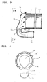
- FIG. 3 and 4 show the embodiment directed to an exhaust emission control device substantially similar to that shown in Figs. 1 and 2 .
- an introductory part 14 which encircles an inlet end of a selective reduction catalyst 6 to guide exhaust gas 3 from a direction substantially perpendicular to an axis of the selective reduction catalyst 6 through an exhaust inlet port 13.
- the introductory part 14 has a depression 15 (first depression) which is cumbered away from the inlet end of the selective reduction catalyst 6 and which approaches toward the inlet end of the selective reduction catalyst 6 as it extends away from the exhaust inlet port 13 toward the introduction direction of the exhaust gas.
- a mixing pipe 16 (exhaust passage) extending to an inlet side of the selective reduction catalyst 6 is integrally formed with the exhaust inlet port 13 at the introductory part 14. Formed just in front of a curved portion provided by the mixing pipe 16 and the exhaust inlet port 13 is a depression 17 (second depression) which guides the exhaust gas flowing inwardly of the turning direction to outward.
- the portion of the mixing pipe 16 formed with the depression 17 is vertically expanded in cross section as shown in Fig. 4 so that the cross-sectional area of the passage do not greatly change before and after the depression 17.
- the exhaust gas 3 introduced into the introductory part 14 through the exhaust inlet port 13 from the direction substantially perpendicular to the axis of the selective reduction catalyst 6 flows axially of the selective reduction catalyst 6 through turnabout, with the flow of the exhaust gas 3 directed outwardly of the turning direction being suppressed by the depression 15 and that of the exhaust gas directed inwardly of the turnabout being induced.
- the tendency of the flow of relatively much exhaust gas 3 biased outwardly of the turning direction is rectified to uniformiaze the distribution of the exhaust gas 3 flow into the selective reduction catalyst 6.
- the depression 17 is formed just in front of the curved portion constituted by the mixing pipe 16 and the exhaust inlet port 13 so as to guide the flow of the exhaust gas 3 inwardly of the turning direction toward outward, so that even if center-to-center distance between the mixing pipe 16 and the selective reduction catalyst 6 is fixed and unchangeable from layout restrictions, the depression 17 causes the portion of the exhaust passage inwardly of the turning direction once directed outward at a position just in front of the curved portion so that a curvature of the curved portion can be reduced for alleviation of pace of curving, resulting in guidance of the exhaust gas flow into the exhaust inlet port 13 in a smooth manner as much as possible.
- the exhaust gas 3 can be introduced into the selective reduction catalyst 6 through the turnabout with distribution of the flow of the exhaust gas 3 being uniformized, so that the whole volume of the selective reduction catalyst 6 can be efficiently utilized for exertion of sufficient NO x reduction effect, resulting in sufficient bringing-out of the exhaust depuration ability of the selective reduction catalyst 6 to be inherently exerted.
- formation of the depression 17 just in front of the curved portion constituted by the mixing pipe 16 and the exhaust inlet port 13 makes it possible to reduce the curvature of the curved portion for alleviation of pace of curving and to guide the flow of the exhaust gas 3 into the exhaust inlet port 13 with a smooth manner as much as possible.
- the tendency of relatively much exhaust gas 3 biased outwardly of the turning direction can be further rectified and substantial increase in pressure loss due to turnabout of the exhaust gas 3 can be prevented.
- the selective reduction catalyst 6 using the urea water as the reduced catalyst constitutes the post-treatment unit, meritoriously overcome are the possibility that the misty urea water may collide against an inner wall of the curved portion owing to increased pressure loss because of the turnabout of the exhaust gas to induce the deposition of urea and the possibility that arrangement of a dispersion plate on the inlet side of the selective reduction catalyst 6 may cause the misty urea water to collides against the dispersion plate to induce the deposition of urea.
- an exhaust emission control device is not limited to the above-mentioned embodiment and that various changes and modifications may be made without departing from the scope of the invention.
- the invention is applied to the inlet side of the selective reduction catalyst in a case where the particulate filter is arranged in parallel with the selective reduction catalyst; however, the invention may be also similarly applicable to any post-treatment unit other than the selective reduction catalyst.
- the invention may be also applicable to exhaust emission control devices of various type with layouts using turnabout of the exhaust gas into the post-treatment unit.
Landscapes
- Engineering & Computer Science (AREA)
- Chemical & Material Sciences (AREA)
- Chemical Kinetics & Catalysis (AREA)
- Combustion & Propulsion (AREA)
- Mechanical Engineering (AREA)
- General Engineering & Computer Science (AREA)
- Health & Medical Sciences (AREA)
- Toxicology (AREA)
- Exhaust Gas After Treatment (AREA)
- Exhaust Gas Treatment By Means Of Catalyst (AREA)
Applications Claiming Priority (2)
| Application Number | Priority Date | Filing Date | Title |
|---|---|---|---|
| JP2007237907A JP4920532B2 (ja) | 2007-09-13 | 2007-09-13 | 排気浄化装置 |
| PCT/JP2008/000609 WO2009034664A1 (ja) | 2007-09-13 | 2008-03-17 | 排気浄化装置 |
Publications (3)
| Publication Number | Publication Date |
|---|---|
| EP2187010A1 true EP2187010A1 (de) | 2010-05-19 |
| EP2187010A4 EP2187010A4 (de) | 2011-04-13 |
| EP2187010B1 EP2187010B1 (de) | 2017-04-19 |
Family
ID=40451687
Family Applications (1)
| Application Number | Title | Priority Date | Filing Date |
|---|---|---|---|
| EP08720494.7A Not-in-force EP2187010B1 (de) | 2007-09-13 | 2008-03-17 | Abgasreinigungsvorrichtung |
Country Status (5)
| Country | Link |
|---|---|
| US (1) | US8327630B2 (de) |
| EP (1) | EP2187010B1 (de) |
| JP (1) | JP4920532B2 (de) |
| CN (1) | CN101878356B (de) |
| WO (1) | WO2009034664A1 (de) |
Cited By (1)
| Publication number | Priority date | Publication date | Assignee | Title |
|---|---|---|---|---|
| EP2199554A4 (de) * | 2007-09-28 | 2013-03-06 | Ud Trucks Corp | Abgasreinigungsvorrichtungen |
Families Citing this family (16)
| Publication number | Priority date | Publication date | Assignee | Title |
|---|---|---|---|---|
| CN102741517B (zh) * | 2009-12-23 | 2016-03-09 | 卡特彼勒公司 | 废气后处理系统 |
| JP5890661B2 (ja) * | 2011-11-16 | 2016-03-22 | 日野自動車株式会社 | 排気浄化装置 |
| JP5855430B2 (ja) * | 2011-11-16 | 2016-02-09 | 日野自動車株式会社 | 排気浄化装置 |
| JP5990025B2 (ja) | 2012-04-12 | 2016-09-07 | 日野自動車株式会社 | ミキシング構造 |
| KR20140091566A (ko) | 2012-07-05 | 2014-07-21 | 가부시키가이샤 고마쓰 세이사쿠쇼 | 엔진 유닛 및 작업 차량 |
| JP6055305B2 (ja) * | 2012-12-26 | 2016-12-27 | ヤンマー株式会社 | 排気ガス浄化装置 |
| CN104066943B (zh) | 2013-01-17 | 2016-08-24 | 株式会社小松制作所 | 还原剂水溶液混合装置及具备它的废气后处理装置 |
| WO2014112072A1 (ja) | 2013-01-17 | 2014-07-24 | 株式会社小松製作所 | 還元剤水溶液ミキシング装置およびこれを備えた排気ガス後処理装置 |
| US8893481B2 (en) | 2013-01-17 | 2014-11-25 | Komatsu Ltd. | Reductant aqueous solution mixing device and exhaust aftertreatment device provided with the same |
| CN104066941B (zh) | 2013-01-17 | 2016-01-20 | 株式会社小松制作所 | 还原剂水溶液混合装置以及具备其的排气后处理装置 |
| JP6571451B2 (ja) * | 2015-08-27 | 2019-09-04 | 日野自動車株式会社 | 排気浄化装置 |
| JP6752733B2 (ja) * | 2017-02-03 | 2020-09-09 | 日野自動車株式会社 | 排気浄化装置 |
| JP6756644B2 (ja) * | 2017-03-09 | 2020-09-16 | 日野自動車株式会社 | 排気浄化装置 |
| CN110056415A (zh) * | 2018-01-19 | 2019-07-26 | 天纳克(苏州)排放系统有限公司 | 发动机排气后处理装置 |
| JP7251997B2 (ja) * | 2019-02-05 | 2023-04-04 | フタバ産業株式会社 | 排気浄化装置 |
| JP7590308B2 (ja) * | 2021-11-26 | 2024-11-26 | フタバ産業株式会社 | 排ガス浄化装置 |
Family Cites Families (13)
| Publication number | Priority date | Publication date | Assignee | Title |
|---|---|---|---|---|
| CA972972A (en) * | 1972-04-07 | 1975-08-19 | Ford Motor Company Of Canada | Gas distribution system for a catalytic converter |
| DE2345383A1 (de) * | 1973-09-08 | 1975-03-20 | Daimler Benz Ag | Verbrennungsmotor mit nachverbrennungseinrichtung |
| JPS5222708B2 (de) * | 1973-11-26 | 1977-06-18 | ||
| JP3318696B2 (ja) * | 1994-07-05 | 2002-08-26 | 新日本製鐵株式会社 | 内燃機関の排気浄化装置 |
| DE19633563C2 (de) | 1996-08-21 | 1999-04-01 | Porsche Ag | Abgasanlage einer Brennkraftmaschine |
| FR2772071B1 (fr) * | 1997-12-05 | 2000-01-14 | Renault | Dispositif d'echappement pour moteur a combustion interne |
| JP2005155404A (ja) * | 2003-11-25 | 2005-06-16 | Komatsu Ltd | 内燃機関の排気ガス浄化装置 |
| JP2006017018A (ja) * | 2004-06-30 | 2006-01-19 | Toyota Motor Corp | 車両用排気管路の構造 |
| FR2874649B1 (fr) * | 2004-08-31 | 2008-02-22 | Faurecia Sys Echappement | Organe de purification catalytique |
| JP4641952B2 (ja) * | 2006-02-08 | 2011-03-02 | 本田技研工業株式会社 | 排気触媒装置を備える多気筒内燃機関 |
| JP4785766B2 (ja) * | 2007-02-09 | 2011-10-05 | 日野自動車株式会社 | 排気浄化装置 |
| JP4928304B2 (ja) | 2007-02-23 | 2012-05-09 | 日野自動車株式会社 | 排気浄化装置 |
| DE202007010435U1 (de) * | 2007-07-26 | 2007-10-25 | Heinrich Gillet Gmbh | Abgasanlage für Nutzfahrzeuge |
-
2007
- 2007-09-13 JP JP2007237907A patent/JP4920532B2/ja active Active
-
2008
- 2008-03-17 US US12/677,957 patent/US8327630B2/en active Active
- 2008-03-17 CN CN200880107158.1A patent/CN101878356B/zh not_active Expired - Fee Related
- 2008-03-17 WO PCT/JP2008/000609 patent/WO2009034664A1/ja not_active Ceased
- 2008-03-17 EP EP08720494.7A patent/EP2187010B1/de not_active Not-in-force
Cited By (1)
| Publication number | Priority date | Publication date | Assignee | Title |
|---|---|---|---|---|
| EP2199554A4 (de) * | 2007-09-28 | 2013-03-06 | Ud Trucks Corp | Abgasreinigungsvorrichtungen |
Also Published As
| Publication number | Publication date |
|---|---|
| US20110214416A1 (en) | 2011-09-08 |
| JP4920532B2 (ja) | 2012-04-18 |
| CN101878356A (zh) | 2010-11-03 |
| WO2009034664A1 (ja) | 2009-03-19 |
| CN101878356B (zh) | 2014-09-17 |
| JP2009068415A (ja) | 2009-04-02 |
| US8327630B2 (en) | 2012-12-11 |
| EP2187010B1 (de) | 2017-04-19 |
| EP2187010A4 (de) | 2011-04-13 |
Similar Documents
| Publication | Publication Date | Title |
|---|---|---|
| EP2187010B1 (de) | Abgasreinigungsvorrichtung | |
| EP2192284B1 (de) | Abgasemissionssteuerungsvorrichtung | |
| EP2295756B1 (de) | Abgasemissionssteuervorrichtung | |
| EP2184458B1 (de) | Vorrichtung zur steuerung von abgasemissionen | |
| EP2204556B1 (de) | Abgasemissions-steuervorrichtung | |
| EP2128398B1 (de) | Abgasemissionssteuervorrichtung | |
| US9217348B2 (en) | Exhaust gas purification device | |
| CN104487666B (zh) | 排气净化装置 | |
| EP2202390B2 (de) | Abgasemissionssteuervorrichtung | |
| CN104040130B (zh) | 排气净化装置 | |
| EP3093463B1 (de) | Abgasreinigungsvorrichtung | |
| JP2020045774A (ja) | インジェクタ及び排気浄化装置 | |
| CN214660448U (zh) | 排气系统 | |
| EP3578772A1 (de) | Abgasreinigungsvorrichtung | |
| JP2013104393A (ja) | 排気浄化装置 | |
| CN114135369A (zh) | 催化器壳体、催化器、排气系统、汽车以及汽车的装配方法 |
Legal Events
| Date | Code | Title | Description |
|---|---|---|---|
| PUAI | Public reference made under article 153(3) epc to a published international application that has entered the european phase |
Free format text: ORIGINAL CODE: 0009012 |
|
| 17P | Request for examination filed |
Effective date: 20100225 |
|
| AK | Designated contracting states |
Kind code of ref document: A1 Designated state(s): AT BE BG CH CY CZ DE DK EE ES FI FR GB GR HR HU IE IS IT LI LT LU LV MC MT NL NO PL PT RO SE SI SK TR |
|
| AX | Request for extension of the european patent |
Extension state: AL BA MK RS |
|
| DAX | Request for extension of the european patent (deleted) | ||
| A4 | Supplementary search report drawn up and despatched |
Effective date: 20110314 |
|
| 17Q | First examination report despatched |
Effective date: 20131203 |
|
| GRAP | Despatch of communication of intention to grant a patent |
Free format text: ORIGINAL CODE: EPIDOSNIGR1 |
|
| INTG | Intention to grant announced |
Effective date: 20160620 |
|
| GRAJ | Information related to disapproval of communication of intention to grant by the applicant or resumption of examination proceedings by the epo deleted |
Free format text: ORIGINAL CODE: EPIDOSDIGR1 |
|
| GRAP | Despatch of communication of intention to grant a patent |
Free format text: ORIGINAL CODE: EPIDOSNIGR1 |
|
| INTC | Intention to grant announced (deleted) | ||
| INTG | Intention to grant announced |
Effective date: 20161031 |
|
| STAA | Information on the status of an ep patent application or granted ep patent |
Free format text: STATUS: GRANT OF PATENT IS INTENDED |
|
| GRAS | Grant fee paid |
Free format text: ORIGINAL CODE: EPIDOSNIGR3 |
|
| GRAA | (expected) grant |
Free format text: ORIGINAL CODE: 0009210 |
|
| STAA | Information on the status of an ep patent application or granted ep patent |
Free format text: STATUS: THE PATENT HAS BEEN GRANTED |
|
| AK | Designated contracting states |
Kind code of ref document: B1 Designated state(s): AT BE BG CH CY CZ DE DK EE ES FI FR GB GR HR HU IE IS IT LI LT LU LV MC MT NL NO PL PT RO SE SI SK TR |
|
| REG | Reference to a national code |
Ref country code: GB Ref legal event code: FG4D |
|
| REG | Reference to a national code |
Ref country code: CH Ref legal event code: EP |
|
| REG | Reference to a national code |
Ref country code: AT Ref legal event code: REF Ref document number: 886196 Country of ref document: AT Kind code of ref document: T Effective date: 20170515 |
|
| REG | Reference to a national code |
Ref country code: IE Ref legal event code: FG4D |
|
| REG | Reference to a national code |
Ref country code: DE Ref legal event code: R096 Ref document number: 602008049827 Country of ref document: DE |
|
| REG | Reference to a national code |
Ref country code: NL Ref legal event code: MP Effective date: 20170419 |
|
| REG | Reference to a national code |
Ref country code: LT Ref legal event code: MG4D |
|
| REG | Reference to a national code |
Ref country code: AT Ref legal event code: MK05 Ref document number: 886196 Country of ref document: AT Kind code of ref document: T Effective date: 20170419 |
|
| PG25 | Lapsed in a contracting state [announced via postgrant information from national office to epo] |
Ref country code: NL Free format text: LAPSE BECAUSE OF FAILURE TO SUBMIT A TRANSLATION OF THE DESCRIPTION OR TO PAY THE FEE WITHIN THE PRESCRIBED TIME-LIMIT Effective date: 20170419 |
|
| PG25 | Lapsed in a contracting state [announced via postgrant information from national office to epo] |
Ref country code: LT Free format text: LAPSE BECAUSE OF FAILURE TO SUBMIT A TRANSLATION OF THE DESCRIPTION OR TO PAY THE FEE WITHIN THE PRESCRIBED TIME-LIMIT Effective date: 20170419 Ref country code: ES Free format text: LAPSE BECAUSE OF FAILURE TO SUBMIT A TRANSLATION OF THE DESCRIPTION OR TO PAY THE FEE WITHIN THE PRESCRIBED TIME-LIMIT Effective date: 20170419 Ref country code: HR Free format text: LAPSE BECAUSE OF FAILURE TO SUBMIT A TRANSLATION OF THE DESCRIPTION OR TO PAY THE FEE WITHIN THE PRESCRIBED TIME-LIMIT Effective date: 20170419 Ref country code: FI Free format text: LAPSE BECAUSE OF FAILURE TO SUBMIT A TRANSLATION OF THE DESCRIPTION OR TO PAY THE FEE WITHIN THE PRESCRIBED TIME-LIMIT Effective date: 20170419 Ref country code: NO Free format text: LAPSE BECAUSE OF FAILURE TO SUBMIT A TRANSLATION OF THE DESCRIPTION OR TO PAY THE FEE WITHIN THE PRESCRIBED TIME-LIMIT Effective date: 20170719 Ref country code: GR Free format text: LAPSE BECAUSE OF FAILURE TO SUBMIT A TRANSLATION OF THE DESCRIPTION OR TO PAY THE FEE WITHIN THE PRESCRIBED TIME-LIMIT Effective date: 20170720 Ref country code: AT Free format text: LAPSE BECAUSE OF FAILURE TO SUBMIT A TRANSLATION OF THE DESCRIPTION OR TO PAY THE FEE WITHIN THE PRESCRIBED TIME-LIMIT Effective date: 20170419 |
|
| PG25 | Lapsed in a contracting state [announced via postgrant information from national office to epo] |
Ref country code: SE Free format text: LAPSE BECAUSE OF FAILURE TO SUBMIT A TRANSLATION OF THE DESCRIPTION OR TO PAY THE FEE WITHIN THE PRESCRIBED TIME-LIMIT Effective date: 20170419 Ref country code: BG Free format text: LAPSE BECAUSE OF FAILURE TO SUBMIT A TRANSLATION OF THE DESCRIPTION OR TO PAY THE FEE WITHIN THE PRESCRIBED TIME-LIMIT Effective date: 20170719 Ref country code: IS Free format text: LAPSE BECAUSE OF FAILURE TO SUBMIT A TRANSLATION OF THE DESCRIPTION OR TO PAY THE FEE WITHIN THE PRESCRIBED TIME-LIMIT Effective date: 20170819 Ref country code: PL Free format text: LAPSE BECAUSE OF FAILURE TO SUBMIT A TRANSLATION OF THE DESCRIPTION OR TO PAY THE FEE WITHIN THE PRESCRIBED TIME-LIMIT Effective date: 20170419 Ref country code: LV Free format text: LAPSE BECAUSE OF FAILURE TO SUBMIT A TRANSLATION OF THE DESCRIPTION OR TO PAY THE FEE WITHIN THE PRESCRIBED TIME-LIMIT Effective date: 20170419 |
|
| REG | Reference to a national code |
Ref country code: DE Ref legal event code: R097 Ref document number: 602008049827 Country of ref document: DE |
|
| PG25 | Lapsed in a contracting state [announced via postgrant information from national office to epo] |
Ref country code: EE Free format text: LAPSE BECAUSE OF FAILURE TO SUBMIT A TRANSLATION OF THE DESCRIPTION OR TO PAY THE FEE WITHIN THE PRESCRIBED TIME-LIMIT Effective date: 20170419 Ref country code: SK Free format text: LAPSE BECAUSE OF FAILURE TO SUBMIT A TRANSLATION OF THE DESCRIPTION OR TO PAY THE FEE WITHIN THE PRESCRIBED TIME-LIMIT Effective date: 20170419 Ref country code: RO Free format text: LAPSE BECAUSE OF FAILURE TO SUBMIT A TRANSLATION OF THE DESCRIPTION OR TO PAY THE FEE WITHIN THE PRESCRIBED TIME-LIMIT Effective date: 20170419 Ref country code: CZ Free format text: LAPSE BECAUSE OF FAILURE TO SUBMIT A TRANSLATION OF THE DESCRIPTION OR TO PAY THE FEE WITHIN THE PRESCRIBED TIME-LIMIT Effective date: 20170419 Ref country code: DK Free format text: LAPSE BECAUSE OF FAILURE TO SUBMIT A TRANSLATION OF THE DESCRIPTION OR TO PAY THE FEE WITHIN THE PRESCRIBED TIME-LIMIT Effective date: 20170419 |
|
| PLBE | No opposition filed within time limit |
Free format text: ORIGINAL CODE: 0009261 |
|
| STAA | Information on the status of an ep patent application or granted ep patent |
Free format text: STATUS: NO OPPOSITION FILED WITHIN TIME LIMIT |
|
| PG25 | Lapsed in a contracting state [announced via postgrant information from national office to epo] |
Ref country code: IT Free format text: LAPSE BECAUSE OF FAILURE TO SUBMIT A TRANSLATION OF THE DESCRIPTION OR TO PAY THE FEE WITHIN THE PRESCRIBED TIME-LIMIT Effective date: 20170419 |
|
| 26N | No opposition filed |
Effective date: 20180122 |
|
| PG25 | Lapsed in a contracting state [announced via postgrant information from national office to epo] |
Ref country code: SI Free format text: LAPSE BECAUSE OF FAILURE TO SUBMIT A TRANSLATION OF THE DESCRIPTION OR TO PAY THE FEE WITHIN THE PRESCRIBED TIME-LIMIT Effective date: 20170419 |
|
| REG | Reference to a national code |
Ref country code: CH Ref legal event code: PL |
|
| PG25 | Lapsed in a contracting state [announced via postgrant information from national office to epo] |
Ref country code: MC Free format text: LAPSE BECAUSE OF FAILURE TO SUBMIT A TRANSLATION OF THE DESCRIPTION OR TO PAY THE FEE WITHIN THE PRESCRIBED TIME-LIMIT Effective date: 20170419 |
|
| REG | Reference to a national code |
Ref country code: BE Ref legal event code: MM Effective date: 20180331 |
|
| REG | Reference to a national code |
Ref country code: IE Ref legal event code: MM4A |
|
| PG25 | Lapsed in a contracting state [announced via postgrant information from national office to epo] |
Ref country code: LU Free format text: LAPSE BECAUSE OF NON-PAYMENT OF DUE FEES Effective date: 20180317 |
|
| PG25 | Lapsed in a contracting state [announced via postgrant information from national office to epo] |
Ref country code: IE Free format text: LAPSE BECAUSE OF NON-PAYMENT OF DUE FEES Effective date: 20180317 |
|
| PG25 | Lapsed in a contracting state [announced via postgrant information from national office to epo] |
Ref country code: BE Free format text: LAPSE BECAUSE OF NON-PAYMENT OF DUE FEES Effective date: 20180331 Ref country code: LI Free format text: LAPSE BECAUSE OF NON-PAYMENT OF DUE FEES Effective date: 20180331 Ref country code: CH Free format text: LAPSE BECAUSE OF NON-PAYMENT OF DUE FEES Effective date: 20180331 |
|
| PG25 | Lapsed in a contracting state [announced via postgrant information from national office to epo] |
Ref country code: FR Free format text: LAPSE BECAUSE OF NON-PAYMENT OF DUE FEES Effective date: 20180331 |
|
| PG25 | Lapsed in a contracting state [announced via postgrant information from national office to epo] |
Ref country code: MT Free format text: LAPSE BECAUSE OF NON-PAYMENT OF DUE FEES Effective date: 20180317 |
|
| PG25 | Lapsed in a contracting state [announced via postgrant information from national office to epo] |
Ref country code: TR Free format text: LAPSE BECAUSE OF FAILURE TO SUBMIT A TRANSLATION OF THE DESCRIPTION OR TO PAY THE FEE WITHIN THE PRESCRIBED TIME-LIMIT Effective date: 20170419 |
|
| PG25 | Lapsed in a contracting state [announced via postgrant information from national office to epo] |
Ref country code: HU Free format text: LAPSE BECAUSE OF FAILURE TO SUBMIT A TRANSLATION OF THE DESCRIPTION OR TO PAY THE FEE WITHIN THE PRESCRIBED TIME-LIMIT; INVALID AB INITIO Effective date: 20080317 Ref country code: PT Free format text: LAPSE BECAUSE OF FAILURE TO SUBMIT A TRANSLATION OF THE DESCRIPTION OR TO PAY THE FEE WITHIN THE PRESCRIBED TIME-LIMIT Effective date: 20170419 |
|
| PG25 | Lapsed in a contracting state [announced via postgrant information from national office to epo] |
Ref country code: CY Free format text: LAPSE BECAUSE OF FAILURE TO SUBMIT A TRANSLATION OF THE DESCRIPTION OR TO PAY THE FEE WITHIN THE PRESCRIBED TIME-LIMIT Effective date: 20170419 |
|
| PGFP | Annual fee paid to national office [announced via postgrant information from national office to epo] |
Ref country code: DE Payment date: 20240307 Year of fee payment: 17 Ref country code: GB Payment date: 20240219 Year of fee payment: 17 |
|
| REG | Reference to a national code |
Ref country code: DE Ref legal event code: R119 Ref document number: 602008049827 Country of ref document: DE |
|
| GBPC | Gb: european patent ceased through non-payment of renewal fee |
Effective date: 20250317 |
|
| PG25 | Lapsed in a contracting state [announced via postgrant information from national office to epo] |
Ref country code: DE Free format text: LAPSE BECAUSE OF NON-PAYMENT OF DUE FEES Effective date: 20251001 |
|
| PG25 | Lapsed in a contracting state [announced via postgrant information from national office to epo] |
Ref country code: GB Free format text: LAPSE BECAUSE OF NON-PAYMENT OF DUE FEES Effective date: 20250317 |