EP2187117A2 - Phare de véhicule - Google Patents
Phare de véhicule Download PDFInfo
- Publication number
- EP2187117A2 EP2187117A2 EP09175477A EP09175477A EP2187117A2 EP 2187117 A2 EP2187117 A2 EP 2187117A2 EP 09175477 A EP09175477 A EP 09175477A EP 09175477 A EP09175477 A EP 09175477A EP 2187117 A2 EP2187117 A2 EP 2187117A2
- Authority
- EP
- European Patent Office
- Prior art keywords
- lamp
- vehicle headlamp
- lamp unit
- main reflector
- reflector
- Prior art date
- Legal status (The legal status is an assumption and is not a legal conclusion. Google has not performed a legal analysis and makes no representation as to the accuracy of the status listed.)
- Granted
Links
- 238000009792 diffusion process Methods 0.000 description 11
- 239000000758 substrate Substances 0.000 description 5
- 238000005286 illumination Methods 0.000 description 2
- 230000004048 modification Effects 0.000 description 2
- 238000012986 modification Methods 0.000 description 2
- 230000003287 optical effect Effects 0.000 description 2
- 239000004065 semiconductor Substances 0.000 description 2
- 229910010293 ceramic material Inorganic materials 0.000 description 1
- 230000005611 electricity Effects 0.000 description 1
- 239000000463 material Substances 0.000 description 1
Images


Classifications
-
- B—PERFORMING OPERATIONS; TRANSPORTING
- B60—VEHICLES IN GENERAL
- B60Q—ARRANGEMENT OF SIGNALLING OR LIGHTING DEVICES, THE MOUNTING OR SUPPORTING THEREOF OR CIRCUITS THEREFOR, FOR VEHICLES IN GENERAL
- B60Q1/00—Arrangement of optical signalling or lighting devices, the mounting or supporting thereof or circuits therefor
- B60Q1/0029—Spatial arrangement
- B60Q1/0041—Spatial arrangement of several lamps in relation to each other
-
- F—MECHANICAL ENGINEERING; LIGHTING; HEATING; WEAPONS; BLASTING
- F21—LIGHTING
- F21S—NON-PORTABLE LIGHTING DEVICES; SYSTEMS THEREOF; VEHICLE LIGHTING DEVICES SPECIALLY ADAPTED FOR VEHICLE EXTERIORS
- F21S41/00—Illuminating devices specially adapted for vehicle exteriors, e.g. headlamps
- F21S41/30—Illuminating devices specially adapted for vehicle exteriors, e.g. headlamps characterised by reflectors
- F21S41/32—Optical layout thereof
- F21S41/33—Multi-surface reflectors, e.g. reflectors with facets or reflectors with portions of different curvature
- F21S41/338—Multi-surface reflectors, e.g. reflectors with facets or reflectors with portions of different curvature the reflector having surface portions added to its general concavity
-
- B—PERFORMING OPERATIONS; TRANSPORTING
- B60—VEHICLES IN GENERAL
- B60Q—ARRANGEMENT OF SIGNALLING OR LIGHTING DEVICES, THE MOUNTING OR SUPPORTING THEREOF OR CIRCUITS THEREFOR, FOR VEHICLES IN GENERAL
- B60Q2400/00—Special features or arrangements of exterior signal lamps for vehicles
- B60Q2400/30—Daytime running lights [DRL], e.g. circuits or arrangements therefor
-
- F—MECHANICAL ENGINEERING; LIGHTING; HEATING; WEAPONS; BLASTING
- F21—LIGHTING
- F21S—NON-PORTABLE LIGHTING DEVICES; SYSTEMS THEREOF; VEHICLE LIGHTING DEVICES SPECIALLY ADAPTED FOR VEHICLE EXTERIORS
- F21S41/00—Illuminating devices specially adapted for vehicle exteriors, e.g. headlamps
- F21S41/10—Illuminating devices specially adapted for vehicle exteriors, e.g. headlamps characterised by the light source
- F21S41/14—Illuminating devices specially adapted for vehicle exteriors, e.g. headlamps characterised by the light source characterised by the type of light source
- F21S41/141—Light emitting diodes [LED]
-
- F—MECHANICAL ENGINEERING; LIGHTING; HEATING; WEAPONS; BLASTING
- F21—LIGHTING
- F21Y—INDEXING SCHEME ASSOCIATED WITH SUBCLASSES F21K, F21L, F21S and F21V, RELATING TO THE FORM OR THE KIND OF THE LIGHT SOURCES OR OF THE COLOUR OF THE LIGHT EMITTED
- F21Y2101/00—Point-like light sources
-
- F—MECHANICAL ENGINEERING; LIGHTING; HEATING; WEAPONS; BLASTING
- F21—LIGHTING
- F21Y—INDEXING SCHEME ASSOCIATED WITH SUBCLASSES F21K, F21L, F21S and F21V, RELATING TO THE FORM OR THE KIND OF THE LIGHT SOURCES OR OF THE COLOUR OF THE LIGHT EMITTED
- F21Y2115/00—Light-generating elements of semiconductor light sources
- F21Y2115/10—Light-emitting diodes [LED]
Definitions
- Apparatuses consistent with the present invention relate to a vehicle headlamp, particularly to a vehicle headlamp having a function of a daytime running lamp.
- a related art vehicle headlamp which is sometimes called a combination headlamp, has a lamp housing, which is formed by a lamp body and a cover, and inside which an auxiliary illumination lamp (e.g., a fog lamp) and/or a signal lamp (e.g., a clearance lamp, a turn signal lamp, etc.) are incorporated with a primary illumination lamp (e.g., a high beam lamp and/or a low beam lamp).
- a daytime running lamp is sometimes mounted inside the lamp housing of the vehicle headlamp. The daytime running lamp is turned on during the daytime to inform pedestrians and oncoming vehicles of the presence of the vehicle (see, e.g., JP 2006-164909 A ).
- the vehicle headlamp becomes large.
- Illustrative aspects of the present invention provide a compact vehicle headlamp having a plurality of lamps.
- a vehicle headlamp includes a lamp body having a front opening, a cover which covers the front opening of the lamp body to form a lamp housing, a first lamp unit which is disposed inside the lamp housing to produce at least one of a high beam and a low beam, and a second lamp unit disposed in a gap region between the lamp body and the first lamp unit to produce a beam other than the high beam and the low beam.
- Fig. 1 is a front view of a vehicle headlamp according to an exemplary embodiment of the present invention
- Fig. 2 is a front view of a daytime running lamp
- Fig. 3 is a sectional view of the daytime running lamp taken along the line III-III of Fig. 2 ;
- Fig. 4 is another sectional view of the daytime running lamp taken along the line IV-IV of Fig. 2 ;
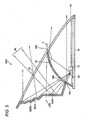
- Fig. 5 is a sectional view of a modified example of the daytime running lamp.
- Fig. 1 is a front view of a vehicle headlamp 100 according to the exemplary embodiment of the present invention.
- the vehicle headlamp 100 has a lamp body 104 having a front opening and a transparent cover 102, which covers the front opening of the lamp body 104.
- the lamp body 104 and the cover 102 form a lamp housing 106.
- the vehicle headlamp 100 further has a low beam lamp 30 (a first lamp unit), a high beam lamp 40 (another first lamp unit), and a daytime running lamp 10 (a second lamp unit), which are disposed inside the lamp housing 106.
- the low beam lamp 30 and the high beam lamp 40 are arranged side-by-side in the lamp housing 106.
- the low beam lamp 30 is turned on when, for example, driving in a city area during the nighttime.
- a configuration of the low beam lamp 30 is not particularly limited.
- the low beam lamp 30 may be a projector-type, which reflects light by a reflector and forwardly projects the light through a projection lens, or the low beam lamp 30 may be a direct-lighting-type, which directly sends forth light emitted from a light source.
- the high beam lamp 40 is turned on when, for example, driving on a general road during the nighttime.
- a configuration of the high beam lamp 40 is not particularly limited. Since various configurations of the low beam lamp and the high beam lamp are well known in the art, a detailed description thereof will be omitted herein.
- the daytime running lamp 10 is turned on during the daytime to inform pedestrians and oncoming vehicles of the presence of the vehicle.
- the daytime running lamp 10 is disposed in a gap region 108 surrounded by a lower wall of the lamp body 104, the low beam lamp 30, and the running beam lamp 40.
- the "gap region" herein implies a special region between the lamp body 104 and a lamp 30, 40 which produces at least one of the high beam and the low beam.
- the gap region is a region where an extension is formed to improve a front appearance of the headlamp.
- an outline of each of the low beam lamp 30 and the high beam lamp 40 is circular, and the lamp body 104 is rectangular. Therefore, the gap region 108 surrounded by the low beam lamp 30, the high beam lamp 40, and the lower wall of the lamp body 104 is triangular in the front view.
- the daytime running lamp 10 is configured to have a triangular shape in the front view so as to fit in the gap region 108 and to fill in the gap region 108.
- the daytime running lamp 10 is disposed in the gap region 108, where an extension would otherwise be arranged. That is, it is not necessary to provide any additional space for the daytime running lamp. Thus, it is possible to reduce the size of the vehicle headlamp 100.
- the gap region 108 in which the daytime running lamp 10 is disposed is not necessarily a region surrounded by the low beam lamp 30, the high beam lamp 40, and the lower wall of the lamp body 104.
- the daytime running lamp 10 may be disposed in a gap region between a left wall of the lamp body 104 and the low beam lamp 30, or in a gap region between a right wall of the lamp body 104 and the high beam lamp 40, etc. (see Fig. 1 ).
- Fig. 2 is a front view of the daytime running lamp 10.
- Fig. 3 is a sectional view of the daytime running lamp 10 taken along the line III-III of Fig. 2 .
- the daytime running lamp 10 has a light source 12, a substrate 14, a support member 16, a main reflector 18, an auxiliary reflector 20, and an inner lens 22.
- the light source 12 is a semiconductor light emitting device such as a light emitting diode (LED), and is arranged on the substrate 14 such that a direction in which light is emitted from the light source 12 is upwardly oriented so as to be perpendicular to an optical axis Ax of the daytime running lamp 10 and such that a light emitting point (or a light emitting face) is positioned on the optical axis Ax.
- the light source 12 is disposed at a central location on the base of the triangular shape of the daytime running lamp 10.
- the substrate 14 is formed of a material, e.g., a ceramic material, having a high thermal conductivity, and is formed with a wiring pattern for supplying electricity to the light source 12.
- the substrate 14 is provided on the support member 16, which is formed in a flat plate-like shape.
- the support member 16 functions as a heat sink for dissipating heat that is generated by the light source 12.
- the main reflector 18 forwardly reflects the light emitted from the light source 12 toward the inner lens 22 to send forth the light in a certain irradiation direction.
- the main reflector 18 is configured and arranged so as to surround the light source 12 from the rear, the sides and the top.
- a surface of the main reflector on a side facing the light source 12 has a reflecting surface 18a. At least a portion of the reflecting surface 18a is formed in a spheroidal shape having a focal point at the location of the light source 12.
- the reflecting surface 18a has a plurality of diffusion steps 18s arranged in a grid-like pattern. Each of the diffusion steps 18s is either a convex step or a concave step.
- the plurality of diffusion steps 18s is configured and arranged such that the light emitted from the light source 12 is diffused to form a light distribution pattern that is required for the daytime running lamp 10.
- the main reflector 18 is fixed and secured to the support member 16 at its lower end portion.
- the main reflector 18 is configured to have a shape that extends along the outlines of the low beam lamp 30 and the high beam lamp 40 which are arranged on respective sides thereof. More specifically, in the front view, the main reflector 18 has a shape with right and left side portions cut to be in a concave arc shape.
- an aperture 18b is formed through the main reflector 18 to allow a part of the light emitted from the light source 12 to pass through the aperture 18b toward the auxiliary reflector 20.
- the aperture 18b is provided rearwardly and obliquely above the light source 12, and is formed in the spheroidal portion of the reflecting surface 18a of the main reflector 18.
- the size and the shape of the aperture 18b may suitably be designed in accordance with a configuration of the auxiliary reflector 20 and the light amount to be reflected by the auxiliary reflector 20.
- the auxiliary reflector 20 forwardly reflects the part of the light from the light source 12, which has passed through the aperture 18b.
- the auxiliary reflector 20 is provided to extend upwardly from a circumferential portion of the aperture 18b on a rear surface 18c of the main reflector 18 in a rearwardly oblique direction.
- the auxiliary reflector 20 is provided to extend, in the front view, and in relation to the triangular shape of the daytime running lamp 10, toward a vertex portion opposite the base on which the light source 12 is disposed.
- the daytime running lamp 10 can be configured to fit into the shape of the gap region 108.
- the auxiliary reflector 20 is formed to have a stepwise configuration which extends upwardly in the rearward oblique direction in a stepped fashion, and in which reflecting surfaces and non-reflecting surfaces are alternately arranged.
- This stepwise configuration of the auxiliary reflector 20 is advantageous in that a length of the daytime running lamp 10 in a depth direction (i.e., in a front-and-rear direction of the vehicle headlamp 100) can be reduced as compared with a non-stepwise configuration.
- Each of the reflecting surfaces of the auxiliary reflector 20 has convex or concave diffusion steps 20s.
- the diffusion steps 20s are configured such that the light that has passed through the aperture 18b is diffused to form, tbgether with the light forwardly reflected by the main reflector 18, the light distribution pattern that is required for the daytime running lamp 10.
- the inner lens 22 is arranged in front of the main reflector 18 and the auxiliary reflector 20.
- the inner lens 22 has lens steps (not shown) which further diffuse the light reflected from the main reflector 18 and the auxiliary reflector 20.
- Standards of a luminous intensity and a luminous area of the daytime running lamp are defined by regulations in each country.
- the luminous intensity at a point H-V on a virtual vertical screen disposed at a position 25m ahead of a vehicle is defined as not less than 400 cd
- the effective luminous area (the area of the apparent surface) in the front view is defined as not less than 25cm 2 and not more than 200cm 2 .
- the daytime running lamp 10 is configured such that an amount of light forwardly reflected from the main reflector 18 is more than the standard amount of light, and such that the total luminous area of the main reflector 18 and the auxiliary reflector 20 is within the range of the standard area.
- the daytime running lamp 10 of the exemplary embodiment can be configured so as to comply with various regulations in each country.
- the size of the reflector needs to be increased, which results in an increase of the entire size of the vehicle headlamp 100.
- the auxiliary reflector 20 is provided in addition to the main reflector 18. Therefore, it is possible to obtain a sufficient luminous area without enlarging the main reflector 18, whereby a compact vehicle headlamp 100 can be provided.
- the auxiliary reflector 20 covers the region behind the aperture 18b as shown in Fig. 3 . Therefore, when the daytime running lamp 10 is viewed from the front, the internal structure (e.g., a substrate, a wiring, etc.) inside the lamp housing 106 is not visible through the aperture 18b. Consequently, it is possible to configure the daytime running lamp 10 without impairing the appearance.
- the internal structure e.g., a substrate, a wiring, etc.
- Fig. 4 is a sectional view of the daytime running lamp 10 taken along the line IV-IV of Fig. 2 .
- the main reflector 18 has multi-stepwise reflectors 18d, 18e on respective sides.
- the multi-stepwise reflectors 18d, 18e are provided at respective end portions of the base of the triangular shape as shown in Fig. 2 .
- Fig. 5 is a vertical sectional view of a daytime running lamp 500 according to a modified example of the exemplary embodiment described above.
- the elements which are the same or correspond to those of the daytime running lamp 10 of Fig. 3 , are denoted using the same reference numerals, and overlapping description thereof will be omitted.
- the daytime running lamp 500 of Fig. 4 is different from the daytime running lamp 10 of Fig. 3 in that a configuration of an auxiliary reflector 520 of the daytime running lamp 500 differs from the auxiliary reflector 20.
- the auxiliary reflector 520 of Fig. 5 also upwardly extends in a rearwardly oblique direction from a circumferential portion of the aperture 18b on the rear surface 18c of the main reflector 18. Further, the auxiliary reflector 520 is provided to extend, in the front view, and in relation to the triangular shape of the daytime running lamp 500, toward a vertex portion opposite the base on which the light source 12 is disposed.
- the auxiliary reflector 520 has reflecting surfaces 520a and non-reflecting surfaces 520b which are arranged in a stepwise manner in a region above the height L of the upper end of the main reflector 18, and another reflecting surface 520c which extends substantially in a vertical direction in a region below the height L of the upper end of the main reflector 18.
- This reflecting surface 520c below the height L of the upper end of the main reflector 18 forwardly reflects a part RL of the light that has passed through the aperture 18b from the light source 12 in an upwardly oblique direction.
- the region below the height L of the upper end of the main reflector 18 becomes dark because a portion of the auxiliary reflector 20 below the height L of the upper end of the main reflector 18 does not reflect light.
- the auxiliary reflector 520 of the modified example has the reflecting surface 520c below the height L of the upper end of the main reflector 18 to forwardly reflect the part RL of the light in the upwardly oblique direction, the region below the height L of the upper end of the main reflector 18 is prevented from becoming dark even when the daytime running lamp 500 is viewed from the front and obliquely from above. Accordingly, it is possible to improve the evenness of the light irradiation from the daytime running lamp 500, which in turn improves the appearance of the daytime running lamp 500.
- the daytime running lamp 500 is different from the daytime running lamp 10 of Fig. 3 only in that the vertically extending reflecting surface 520a is provided. Therefore, the length of the daytime running lamp 500 in the front-and-rear direction of the headlamp 100 is not different from the corresponding length of the daytime running lamp 10.
- the reflecting surface 520a of the auxiliary reflector 520 may have a plurality of convex and/or concave diffuse steps to form a light distribution pattern that is required for the daytime running lamp 500.
- the lamp (the second lamp unit) to be arranged in the gap region 108 may not necessarily be the daytime running lamp 10, 500, and may be other types of lamps such as a fog lamp or a turn signal lamp. Even in those cases, it is possible to reduce the size of the vehicle headlamp 100.
- the light source 12 may not necessarily be the LED, and may be other types of semiconductor light emitting device or a lamp bulb.
- the low beam lamp 30 and the high beam lamp 40 may not necessarily be provided as separate lamp units. That is, a single lamp unit capable of producing the low beam and the high beam may alternatively be provided. In this case, the daytime running lamp 10, 500 is provided in the gap region between the single lamp unit and the lamp body 104.
- the daytime running lamp 10, 500 may not necessarily have a triangular shape in the front view, and may have other shapes that match the shape of the gap region 108.
- the reflecting surfaces 18a of the main reflector 18 and the reflecting surfaces of the auxiliary reflector 20, 520 may not necessarily have the diffusion steps.
- the inner lens 22 may be configured to have a fish-eye lens or lenses to diffuse the light without providing the diffusion steps on the main reflector 18 and the auxiliary reflector 20, 520.
- the main reflector 18 and the auxiliary reflector 20, 520 may be configured to have diffusion steps that diffuse light in right and left directions and the inner lens 22 may be configured to have diffusion steps that diffuse the light in up and down directions, or the main reflector 18 and the auxiliary reflector 20, 520 may be configured to have diffusion steps that diffuse light in the up and down directions and the inner lens 22 may be configured to have diffusion steps that diffuse the light in the right and left directions.
Landscapes
- Engineering & Computer Science (AREA)
- Mechanical Engineering (AREA)
- General Engineering & Computer Science (AREA)
- Non-Portable Lighting Devices Or Systems Thereof (AREA)
- Lighting Device Outwards From Vehicle And Optical Signal (AREA)
Applications Claiming Priority (2)
| Application Number | Priority Date | Filing Date | Title |
|---|---|---|---|
| JP2008288880 | 2008-11-11 | ||
| JP2009216052A JP5460201B2 (ja) | 2008-11-11 | 2009-09-17 | 車両用前照灯 |
Publications (3)
| Publication Number | Publication Date |
|---|---|
| EP2187117A2 true EP2187117A2 (fr) | 2010-05-19 |
| EP2187117A3 EP2187117A3 (fr) | 2011-03-30 |
| EP2187117B1 EP2187117B1 (fr) | 2012-06-27 |
Family
ID=41716185
Family Applications (1)
| Application Number | Title | Priority Date | Filing Date |
|---|---|---|---|
| EP09175477A Not-in-force EP2187117B1 (fr) | 2008-11-11 | 2009-11-10 | Phare de véhicule |
Country Status (3)
| Country | Link |
|---|---|
| US (1) | US8256942B2 (fr) |
| EP (1) | EP2187117B1 (fr) |
| JP (1) | JP5460201B2 (fr) |
Cited By (2)
| Publication number | Priority date | Publication date | Assignee | Title |
|---|---|---|---|---|
| WO2018083395A1 (fr) * | 2016-11-07 | 2018-05-11 | Psa Automobiles Sa | Feu de signalisation de véhicule automobile |
| ES2748207A1 (es) * | 2018-09-13 | 2020-03-13 | Seat Sa | Faro para vehiculo automovil |
Families Citing this family (5)
| Publication number | Priority date | Publication date | Assignee | Title |
|---|---|---|---|---|
| US8714793B2 (en) * | 2012-07-10 | 2014-05-06 | Osram Sylvania Inc. | LED headlight with one or more stepped upward-facing reflectors |
| DE102012017262A1 (de) * | 2012-08-31 | 2014-03-06 | Volkswagen Aktiengesellschaft | Leuchtvorrichtung für ein Fahrzeug |
| US8950912B2 (en) | 2012-10-10 | 2015-02-10 | Federal-Mogul Corporation | Low and high beam headlamp |
| US10378715B2 (en) * | 2017-08-25 | 2019-08-13 | Osram Sylvania Inc. | Solid-state vehicle headlamp having spherodial reflector optic and clamshell reflector |
| JP7193276B2 (ja) * | 2018-09-05 | 2022-12-20 | スタンレー電気株式会社 | 車両用灯具 |
Citations (3)
| Publication number | Priority date | Publication date | Assignee | Title |
|---|---|---|---|---|
| JP2006164909A (ja) | 2004-12-10 | 2006-06-22 | Koito Mfg Co Ltd | デイタイムランニングランプ |
| JP2006236588A (ja) | 2005-02-22 | 2006-09-07 | Koito Mfg Co Ltd | 光照明装置及び車両用灯具 |
| DE102007016294A1 (de) | 2006-04-11 | 2007-10-25 | Koito Manufacturing Co., Ltd. | Fahrzeuglampe |
Family Cites Families (14)
| Publication number | Priority date | Publication date | Assignee | Title |
|---|---|---|---|---|
| JPS6085005U (ja) * | 1983-11-17 | 1985-06-12 | 市光工業株式会社 | 車輌用灯具 |
| DE3519271C1 (de) * | 1985-05-30 | 1986-08-28 | Westfälische Metall Industrie KG Hueck & Co, 4780 Lippstadt | Abgeblendeter Fahrzeugscheinwerfer nach dem Projektionsprinzip |
| JPH0795401B2 (ja) * | 1988-04-05 | 1995-10-11 | 株式会社小糸製作所 | 自動車用前照灯 |
| JP2610088B2 (ja) * | 1993-03-08 | 1997-05-14 | 株式会社小糸製作所 | 補助ランプ内蔵自動車用ヘッドランプ |
| JPH0855502A (ja) * | 1994-08-11 | 1996-02-27 | Koito Mfg Co Ltd | 車両用灯具 |
| JP3145966B2 (ja) * | 1997-09-11 | 2001-03-12 | 株式会社小糸製作所 | 車輌用前照灯 |
| FR2775230B1 (fr) * | 1998-02-23 | 2000-05-12 | Valeo Vision | Ensemble perfectionne d'au moins un projecteur et d'un feu de signalisation, pour vehicule automobile |
| JP2001043708A (ja) * | 1999-07-30 | 2001-02-16 | Honda Motor Co Ltd | 自動二輪車用前照灯 |
| JP2003242812A (ja) * | 2002-02-18 | 2003-08-29 | Koito Mfg Co Ltd | 車両用灯具 |
| JP3897159B2 (ja) * | 2002-03-15 | 2007-03-22 | 株式会社小糸製作所 | リフレクター可動型ヘッドランプ |
| JP2004047354A (ja) * | 2002-07-15 | 2004-02-12 | Fuji Heavy Ind Ltd | 車両用灯具 |
| US7217020B2 (en) * | 2004-11-24 | 2007-05-15 | General Motors Corporation | Headlamp assembly with integrated infrared illuminator |
| JP2007305575A (ja) * | 2006-04-11 | 2007-11-22 | Koito Mfg Co Ltd | 車両用灯具 |
| JP2008251351A (ja) * | 2007-03-30 | 2008-10-16 | Stanley Electric Co Ltd | 車両用灯具 |
-
2009
- 2009-09-17 JP JP2009216052A patent/JP5460201B2/ja not_active Expired - Fee Related
- 2009-11-10 EP EP09175477A patent/EP2187117B1/fr not_active Not-in-force
- 2009-11-11 US US12/616,165 patent/US8256942B2/en not_active Expired - Fee Related
Patent Citations (3)
| Publication number | Priority date | Publication date | Assignee | Title |
|---|---|---|---|---|
| JP2006164909A (ja) | 2004-12-10 | 2006-06-22 | Koito Mfg Co Ltd | デイタイムランニングランプ |
| JP2006236588A (ja) | 2005-02-22 | 2006-09-07 | Koito Mfg Co Ltd | 光照明装置及び車両用灯具 |
| DE102007016294A1 (de) | 2006-04-11 | 2007-10-25 | Koito Manufacturing Co., Ltd. | Fahrzeuglampe |
Cited By (3)
| Publication number | Priority date | Publication date | Assignee | Title |
|---|---|---|---|---|
| WO2018083395A1 (fr) * | 2016-11-07 | 2018-05-11 | Psa Automobiles Sa | Feu de signalisation de véhicule automobile |
| FR3058370A1 (fr) * | 2016-11-07 | 2018-05-11 | Peugeot Citroen Automobiles Sa | Feu de signalisation de vehicule automobile |
| ES2748207A1 (es) * | 2018-09-13 | 2020-03-13 | Seat Sa | Faro para vehiculo automovil |
Also Published As
| Publication number | Publication date |
|---|---|
| EP2187117A3 (fr) | 2011-03-30 |
| US20100118558A1 (en) | 2010-05-13 |
| US8256942B2 (en) | 2012-09-04 |
| JP5460201B2 (ja) | 2014-04-02 |
| EP2187117B1 (fr) | 2012-06-27 |
| JP2010140891A (ja) | 2010-06-24 |
Similar Documents
| Publication | Publication Date | Title |
|---|---|---|
| US8511874B2 (en) | Vehicle lamp | |
| CN102713420B (zh) | 车辆用头灯 | |
| JP5869223B2 (ja) | 車両用前照灯 | |
| US9593818B2 (en) | Vehicular marker lamp | |
| EP2299166B1 (fr) | Unité de lampe pour phare de véhicule | |
| CN102213389B (zh) | 车辆用前照灯 | |
| JP4264319B2 (ja) | 車両用前照灯 | |
| CN103423687B (zh) | 车辆用前照灯 | |
| CN104160207B (zh) | 前照灯用光源以及前照灯 | |
| JP2008243477A (ja) | 車両用灯具 | |
| EP2187117B1 (fr) | Phare de véhicule | |
| JP2013546145A (ja) | Ledランプモジュール | |
| JP6319725B2 (ja) | 照明装置及び照明装置を備える自動車 | |
| JP2014075271A (ja) | 車両用灯具 | |
| EP2075500B1 (fr) | Phare de véhicule | |
| EP2075501B1 (fr) | Phare de véhicule | |
| JP5874901B2 (ja) | 車両用灯具ユニット | |
| JP2013246939A (ja) | 車両用前照灯 | |
| JP4664830B2 (ja) | 車両用灯具 | |
| JP2011025820A (ja) | 車両用灯具 | |
| JP6161504B2 (ja) | 車載用前照灯 | |
| JP2006216337A (ja) | 車両用前照灯 | |
| JP2020004585A (ja) | 車両用前照灯 | |
| JP6471457B2 (ja) | 車両用灯具 | |
| WO2014207817A1 (fr) | Phare de véhicule |
Legal Events
| Date | Code | Title | Description |
|---|---|---|---|
| PUAI | Public reference made under article 153(3) epc to a published international application that has entered the european phase |
Free format text: ORIGINAL CODE: 0009012 |
|
| 17P | Request for examination filed |
Effective date: 20091110 |
|
| AK | Designated contracting states |
Kind code of ref document: A2 Designated state(s): AT BE BG CH CY CZ DE DK EE ES FI FR GB GR HR HU IE IS IT LI LT LU LV MC MK MT NL NO PL PT RO SE SI SK SM TR |
|
| AX | Request for extension of the european patent |
Extension state: AL BA RS |
|
| PUAL | Search report despatched |
Free format text: ORIGINAL CODE: 0009013 |
|
| AK | Designated contracting states |
Kind code of ref document: A3 Designated state(s): AT BE BG CH CY CZ DE DK EE ES FI FR GB GR HR HU IE IS IT LI LT LU LV MC MK MT NL NO PL PT RO SE SI SK SM TR |
|
| AX | Request for extension of the european patent |
Extension state: AL BA RS |
|
| GRAP | Despatch of communication of intention to grant a patent |
Free format text: ORIGINAL CODE: EPIDOSNIGR1 |
|
| GRAS | Grant fee paid |
Free format text: ORIGINAL CODE: EPIDOSNIGR3 |
|
| GRAA | (expected) grant |
Free format text: ORIGINAL CODE: 0009210 |
|
| AK | Designated contracting states |
Kind code of ref document: B1 Designated state(s): AT BE BG CH CY CZ DE DK EE ES FI FR GB GR HR HU IE IS IT LI LT LU LV MC MK MT NL NO PL PT RO SE SI SK SM TR |
|
| REG | Reference to a national code |
Ref country code: GB Ref legal event code: FG4D |
|
| REG | Reference to a national code |
Ref country code: CH Ref legal event code: EP |
|
| REG | Reference to a national code |
Ref country code: AT Ref legal event code: REF Ref document number: 564448 Country of ref document: AT Kind code of ref document: T Effective date: 20120715 |
|
| REG | Reference to a national code |
Ref country code: IE Ref legal event code: FG4D |
|
| REG | Reference to a national code |
Ref country code: DE Ref legal event code: R096 Ref document number: 602009007854 Country of ref document: DE Effective date: 20120823 |
|
| PG25 | Lapsed in a contracting state [announced via postgrant information from national office to epo] |
Ref country code: FI Free format text: LAPSE BECAUSE OF FAILURE TO SUBMIT A TRANSLATION OF THE DESCRIPTION OR TO PAY THE FEE WITHIN THE PRESCRIBED TIME-LIMIT Effective date: 20120627 Ref country code: LT Free format text: LAPSE BECAUSE OF FAILURE TO SUBMIT A TRANSLATION OF THE DESCRIPTION OR TO PAY THE FEE WITHIN THE PRESCRIBED TIME-LIMIT Effective date: 20120627 Ref country code: SE Free format text: LAPSE BECAUSE OF FAILURE TO SUBMIT A TRANSLATION OF THE DESCRIPTION OR TO PAY THE FEE WITHIN THE PRESCRIBED TIME-LIMIT Effective date: 20120627 Ref country code: NO Free format text: LAPSE BECAUSE OF FAILURE TO SUBMIT A TRANSLATION OF THE DESCRIPTION OR TO PAY THE FEE WITHIN THE PRESCRIBED TIME-LIMIT Effective date: 20120927 |
|
| REG | Reference to a national code |
Ref country code: NL Ref legal event code: VDEP Effective date: 20120627 |
|
| REG | Reference to a national code |
Ref country code: AT Ref legal event code: MK05 Ref document number: 564448 Country of ref document: AT Kind code of ref document: T Effective date: 20120627 |
|
| REG | Reference to a national code |
Ref country code: LT Ref legal event code: MG4D Effective date: 20120627 |
|
| PG25 | Lapsed in a contracting state [announced via postgrant information from national office to epo] |
Ref country code: LV Free format text: LAPSE BECAUSE OF FAILURE TO SUBMIT A TRANSLATION OF THE DESCRIPTION OR TO PAY THE FEE WITHIN THE PRESCRIBED TIME-LIMIT Effective date: 20120627 Ref country code: SI Free format text: LAPSE BECAUSE OF FAILURE TO SUBMIT A TRANSLATION OF THE DESCRIPTION OR TO PAY THE FEE WITHIN THE PRESCRIBED TIME-LIMIT Effective date: 20120627 Ref country code: GR Free format text: LAPSE BECAUSE OF FAILURE TO SUBMIT A TRANSLATION OF THE DESCRIPTION OR TO PAY THE FEE WITHIN THE PRESCRIBED TIME-LIMIT Effective date: 20120928 Ref country code: HR Free format text: LAPSE BECAUSE OF FAILURE TO SUBMIT A TRANSLATION OF THE DESCRIPTION OR TO PAY THE FEE WITHIN THE PRESCRIBED TIME-LIMIT Effective date: 20120627 |
|
| PG25 | Lapsed in a contracting state [announced via postgrant information from national office to epo] |
Ref country code: SK Free format text: LAPSE BECAUSE OF FAILURE TO SUBMIT A TRANSLATION OF THE DESCRIPTION OR TO PAY THE FEE WITHIN THE PRESCRIBED TIME-LIMIT Effective date: 20120627 Ref country code: RO Free format text: LAPSE BECAUSE OF FAILURE TO SUBMIT A TRANSLATION OF THE DESCRIPTION OR TO PAY THE FEE WITHIN THE PRESCRIBED TIME-LIMIT Effective date: 20120627 Ref country code: IS Free format text: LAPSE BECAUSE OF FAILURE TO SUBMIT A TRANSLATION OF THE DESCRIPTION OR TO PAY THE FEE WITHIN THE PRESCRIBED TIME-LIMIT Effective date: 20121027 Ref country code: EE Free format text: LAPSE BECAUSE OF FAILURE TO SUBMIT A TRANSLATION OF THE DESCRIPTION OR TO PAY THE FEE WITHIN THE PRESCRIBED TIME-LIMIT Effective date: 20120627 Ref country code: AT Free format text: LAPSE BECAUSE OF FAILURE TO SUBMIT A TRANSLATION OF THE DESCRIPTION OR TO PAY THE FEE WITHIN THE PRESCRIBED TIME-LIMIT Effective date: 20120627 Ref country code: CZ Free format text: LAPSE BECAUSE OF FAILURE TO SUBMIT A TRANSLATION OF THE DESCRIPTION OR TO PAY THE FEE WITHIN THE PRESCRIBED TIME-LIMIT Effective date: 20120627 Ref country code: BE Free format text: LAPSE BECAUSE OF FAILURE TO SUBMIT A TRANSLATION OF THE DESCRIPTION OR TO PAY THE FEE WITHIN THE PRESCRIBED TIME-LIMIT Effective date: 20120627 Ref country code: CY Free format text: LAPSE BECAUSE OF FAILURE TO SUBMIT A TRANSLATION OF THE DESCRIPTION OR TO PAY THE FEE WITHIN THE PRESCRIBED TIME-LIMIT Effective date: 20120627 |
|
| PG25 | Lapsed in a contracting state [announced via postgrant information from national office to epo] |
Ref country code: PT Free format text: LAPSE BECAUSE OF FAILURE TO SUBMIT A TRANSLATION OF THE DESCRIPTION OR TO PAY THE FEE WITHIN THE PRESCRIBED TIME-LIMIT Effective date: 20121029 Ref country code: PL Free format text: LAPSE BECAUSE OF FAILURE TO SUBMIT A TRANSLATION OF THE DESCRIPTION OR TO PAY THE FEE WITHIN THE PRESCRIBED TIME-LIMIT Effective date: 20120627 Ref country code: IT Free format text: LAPSE BECAUSE OF FAILURE TO SUBMIT A TRANSLATION OF THE DESCRIPTION OR TO PAY THE FEE WITHIN THE PRESCRIBED TIME-LIMIT Effective date: 20120627 |
|
| PG25 | Lapsed in a contracting state [announced via postgrant information from national office to epo] |
Ref country code: NL Free format text: LAPSE BECAUSE OF FAILURE TO SUBMIT A TRANSLATION OF THE DESCRIPTION OR TO PAY THE FEE WITHIN THE PRESCRIBED TIME-LIMIT Effective date: 20120627 |
|
| PG25 | Lapsed in a contracting state [announced via postgrant information from national office to epo] |
Ref country code: ES Free format text: LAPSE BECAUSE OF FAILURE TO SUBMIT A TRANSLATION OF THE DESCRIPTION OR TO PAY THE FEE WITHIN THE PRESCRIBED TIME-LIMIT Effective date: 20121008 Ref country code: DK Free format text: LAPSE BECAUSE OF FAILURE TO SUBMIT A TRANSLATION OF THE DESCRIPTION OR TO PAY THE FEE WITHIN THE PRESCRIBED TIME-LIMIT Effective date: 20120627 |
|
| PLBE | No opposition filed within time limit |
Free format text: ORIGINAL CODE: 0009261 |
|
| STAA | Information on the status of an ep patent application or granted ep patent |
Free format text: STATUS: NO OPPOSITION FILED WITHIN TIME LIMIT |
|
| 26N | No opposition filed |
Effective date: 20130328 |
|
| REG | Reference to a national code |
Ref country code: DE Ref legal event code: R097 Ref document number: 602009007854 Country of ref document: DE Effective date: 20130328 |
|
| PG25 | Lapsed in a contracting state [announced via postgrant information from national office to epo] |
Ref country code: BG Free format text: LAPSE BECAUSE OF FAILURE TO SUBMIT A TRANSLATION OF THE DESCRIPTION OR TO PAY THE FEE WITHIN THE PRESCRIBED TIME-LIMIT Effective date: 20120927 |
|
| REG | Reference to a national code |
Ref country code: IE Ref legal event code: MM4A |
|
| PG25 | Lapsed in a contracting state [announced via postgrant information from national office to epo] |
Ref country code: IE Free format text: LAPSE BECAUSE OF NON-PAYMENT OF DUE FEES Effective date: 20121110 |
|
| PG25 | Lapsed in a contracting state [announced via postgrant information from national office to epo] |
Ref country code: MT Free format text: LAPSE BECAUSE OF FAILURE TO SUBMIT A TRANSLATION OF THE DESCRIPTION OR TO PAY THE FEE WITHIN THE PRESCRIBED TIME-LIMIT Effective date: 20120627 |
|
| PGFP | Annual fee paid to national office [announced via postgrant information from national office to epo] |
Ref country code: GB Payment date: 20131106 Year of fee payment: 5 |
|
| PG25 | Lapsed in a contracting state [announced via postgrant information from national office to epo] |
Ref country code: TR Free format text: LAPSE BECAUSE OF FAILURE TO SUBMIT A TRANSLATION OF THE DESCRIPTION OR TO PAY THE FEE WITHIN THE PRESCRIBED TIME-LIMIT Effective date: 20120627 Ref country code: MC Free format text: LAPSE BECAUSE OF NON-PAYMENT OF DUE FEES Effective date: 20121130 |
|
| PG25 | Lapsed in a contracting state [announced via postgrant information from national office to epo] |
Ref country code: LU Free format text: LAPSE BECAUSE OF NON-PAYMENT OF DUE FEES Effective date: 20121110 Ref country code: SM Free format text: LAPSE BECAUSE OF FAILURE TO SUBMIT A TRANSLATION OF THE DESCRIPTION OR TO PAY THE FEE WITHIN THE PRESCRIBED TIME-LIMIT Effective date: 20120627 |
|
| REG | Reference to a national code |
Ref country code: CH Ref legal event code: PL |
|
| PG25 | Lapsed in a contracting state [announced via postgrant information from national office to epo] |
Ref country code: HU Free format text: LAPSE BECAUSE OF FAILURE TO SUBMIT A TRANSLATION OF THE DESCRIPTION OR TO PAY THE FEE WITHIN THE PRESCRIBED TIME-LIMIT Effective date: 20091110 Ref country code: CH Free format text: LAPSE BECAUSE OF NON-PAYMENT OF DUE FEES Effective date: 20131130 Ref country code: LI Free format text: LAPSE BECAUSE OF NON-PAYMENT OF DUE FEES Effective date: 20131130 |
|
| GBPC | Gb: european patent ceased through non-payment of renewal fee |
Effective date: 20141110 |
|
| PG25 | Lapsed in a contracting state [announced via postgrant information from national office to epo] |
Ref country code: MK Free format text: LAPSE BECAUSE OF FAILURE TO SUBMIT A TRANSLATION OF THE DESCRIPTION OR TO PAY THE FEE WITHIN THE PRESCRIBED TIME-LIMIT Effective date: 20120627 |
|
| REG | Reference to a national code |
Ref country code: FR Ref legal event code: PLFP Year of fee payment: 7 |
|
| PG25 | Lapsed in a contracting state [announced via postgrant information from national office to epo] |
Ref country code: GB Free format text: LAPSE BECAUSE OF NON-PAYMENT OF DUE FEES Effective date: 20141110 |
|
| REG | Reference to a national code |
Ref country code: FR Ref legal event code: PLFP Year of fee payment: 8 |
|
| REG | Reference to a national code |
Ref country code: FR Ref legal event code: PLFP Year of fee payment: 9 |
|
| PGFP | Annual fee paid to national office [announced via postgrant information from national office to epo] |
Ref country code: FR Payment date: 20171012 Year of fee payment: 9 Ref country code: DE Payment date: 20171108 Year of fee payment: 9 |
|
| REG | Reference to a national code |
Ref country code: DE Ref legal event code: R119 Ref document number: 602009007854 Country of ref document: DE |
|
| PG25 | Lapsed in a contracting state [announced via postgrant information from national office to epo] |
Ref country code: FR Free format text: LAPSE BECAUSE OF NON-PAYMENT OF DUE FEES Effective date: 20181130 Ref country code: DE Free format text: LAPSE BECAUSE OF NON-PAYMENT OF DUE FEES Effective date: 20190601 |