EP2187145B1 - Poêle à accumulation latent - Google Patents
Poêle à accumulation latent Download PDFInfo
- Publication number
- EP2187145B1 EP2187145B1 EP09012106.2A EP09012106A EP2187145B1 EP 2187145 B1 EP2187145 B1 EP 2187145B1 EP 09012106 A EP09012106 A EP 09012106A EP 2187145 B1 EP2187145 B1 EP 2187145B1
- Authority
- EP
- European Patent Office
- Prior art keywords
- heat
- air
- combustion gas
- heat storage
- latent
- Prior art date
- Legal status (The legal status is an assumption and is not a legal conclusion. Google has not performed a legal analysis and makes no representation as to the accuracy of the status listed.)
- Not-in-force
Links
- 238000005338 heat storage Methods 0.000 claims description 89
- 239000000567 combustion gas Substances 0.000 claims description 71
- 239000011232 storage material Substances 0.000 claims description 43
- 238000002485 combustion reaction Methods 0.000 claims description 33
- 230000008018 melting Effects 0.000 claims description 9
- 238000002844 melting Methods 0.000 claims description 9
- 239000007787 solid Substances 0.000 claims description 7
- 239000008188 pellet Substances 0.000 claims description 4
- 239000004449 solid propellant Substances 0.000 claims description 3
- 229910000831 Steel Inorganic materials 0.000 claims description 2
- 230000001419 dependent effect Effects 0.000 claims description 2
- 239000010959 steel Substances 0.000 claims description 2
- 239000003570 air Substances 0.000 description 92
- OKTJSMMVPCPJKN-UHFFFAOYSA-N Carbon Chemical compound [C] OKTJSMMVPCPJKN-UHFFFAOYSA-N 0.000 description 10
- 229910002804 graphite Inorganic materials 0.000 description 10
- 239000010439 graphite Substances 0.000 description 10
- 239000000463 material Substances 0.000 description 9
- 239000011888 foil Substances 0.000 description 6
- 238000010438 heat treatment Methods 0.000 description 5
- 239000012071 phase Substances 0.000 description 5
- 239000000446 fuel Substances 0.000 description 3
- 230000006870 function Effects 0.000 description 3
- 238000009413 insulation Methods 0.000 description 3
- 239000007791 liquid phase Substances 0.000 description 3
- -1 logs Substances 0.000 description 3
- 230000007704 transition Effects 0.000 description 3
- 239000002023 wood Substances 0.000 description 3
- 230000007797 corrosion Effects 0.000 description 2
- 238000005260 corrosion Methods 0.000 description 2
- 230000017525 heat dissipation Effects 0.000 description 2
- 239000007788 liquid Substances 0.000 description 2
- 239000011159 matrix material Substances 0.000 description 2
- 229910052751 metal Inorganic materials 0.000 description 2
- 239000002184 metal Substances 0.000 description 2
- 230000005855 radiation Effects 0.000 description 2
- 150000003839 salts Chemical class 0.000 description 2
- 239000004575 stone Substances 0.000 description 2
- 239000002028 Biomass Substances 0.000 description 1
- UGFAIRIUMAVXCW-UHFFFAOYSA-N Carbon monoxide Chemical compound [O+]#[C-] UGFAIRIUMAVXCW-UHFFFAOYSA-N 0.000 description 1
- 229910013553 LiNO Inorganic materials 0.000 description 1
- ZOKXTWBITQBERF-UHFFFAOYSA-N Molybdenum Chemical compound [Mo] ZOKXTWBITQBERF-UHFFFAOYSA-N 0.000 description 1
- 229910002651 NO3 Inorganic materials 0.000 description 1
- NHNBFGGVMKEFGY-UHFFFAOYSA-N Nitrate Chemical compound [O-][N+]([O-])=O NHNBFGGVMKEFGY-UHFFFAOYSA-N 0.000 description 1
- WYTGDNHDOZPMIW-RCBQFDQVSA-N alstonine Natural products C1=CC2=C3C=CC=CC3=NC2=C2N1C[C@H]1[C@H](C)OC=C(C(=O)OC)[C@H]1C2 WYTGDNHDOZPMIW-RCBQFDQVSA-N 0.000 description 1
- 239000012080 ambient air Substances 0.000 description 1
- QVGXLLKOCUKJST-UHFFFAOYSA-N atomic oxygen Chemical compound [O] QVGXLLKOCUKJST-UHFFFAOYSA-N 0.000 description 1
- 239000011449 brick Substances 0.000 description 1
- 229910052799 carbon Inorganic materials 0.000 description 1
- 239000003245 coal Substances 0.000 description 1
- 239000004020 conductor Substances 0.000 description 1
- 239000012611 container material Substances 0.000 description 1
- 238000010586 diagram Methods 0.000 description 1
- 238000009826 distribution Methods 0.000 description 1
- 230000009977 dual effect Effects 0.000 description 1
- 238000004146 energy storage Methods 0.000 description 1
- 238000010304 firing Methods 0.000 description 1
- 239000003546 flue gas Substances 0.000 description 1
- 239000007789 gas Substances 0.000 description 1
- 230000005283 ground state Effects 0.000 description 1
- 230000007774 longterm Effects 0.000 description 1
- 229910052750 molybdenum Inorganic materials 0.000 description 1
- 239000011733 molybdenum Substances 0.000 description 1
- 229910021382 natural graphite Inorganic materials 0.000 description 1
- 150000002826 nitrites Chemical class 0.000 description 1
- 229910052760 oxygen Inorganic materials 0.000 description 1
- 239000001301 oxygen Substances 0.000 description 1
- 229910001220 stainless steel Inorganic materials 0.000 description 1
- 239000010935 stainless steel Substances 0.000 description 1
- 238000009827 uniform distribution Methods 0.000 description 1
- 238000010792 warming Methods 0.000 description 1
Images


Classifications
-
- F—MECHANICAL ENGINEERING; LIGHTING; HEATING; WEAPONS; BLASTING
- F24—HEATING; RANGES; VENTILATING
- F24H—FLUID HEATERS, e.g. WATER OR AIR HEATERS, HAVING HEAT-GENERATING MEANS, e.g. HEAT PUMPS, IN GENERAL
- F24H3/00—Air heaters
- F24H3/02—Air heaters with forced circulation
- F24H3/06—Air heaters with forced circulation the air being kept separate from the heating medium, e.g. using forced circulation of air over radiators
- F24H3/08—Air heaters with forced circulation the air being kept separate from the heating medium, e.g. using forced circulation of air over radiators by tubes
- F24H3/088—Air heaters with forced circulation the air being kept separate from the heating medium, e.g. using forced circulation of air over radiators by tubes using solid fuel
-
- F—MECHANICAL ENGINEERING; LIGHTING; HEATING; WEAPONS; BLASTING
- F24—HEATING; RANGES; VENTILATING
- F24H—FLUID HEATERS, e.g. WATER OR AIR HEATERS, HAVING HEAT-GENERATING MEANS, e.g. HEAT PUMPS, IN GENERAL
- F24H7/00—Storage heaters, i.e. heaters in which the energy is stored as heat in masses for subsequent release
- F24H7/02—Storage heaters, i.e. heaters in which the energy is stored as heat in masses for subsequent release the released heat being conveyed to a transfer fluid
- F24H7/04—Storage heaters, i.e. heaters in which the energy is stored as heat in masses for subsequent release the released heat being conveyed to a transfer fluid with forced circulation of the transfer fluid
- F24H7/0475—Storage heaters, i.e. heaters in which the energy is stored as heat in masses for subsequent release the released heat being conveyed to a transfer fluid with forced circulation of the transfer fluid using solid fuel
- F24H7/0483—Storage heaters, i.e. heaters in which the energy is stored as heat in masses for subsequent release the released heat being conveyed to a transfer fluid with forced circulation of the transfer fluid using solid fuel the transfer fluid being air
-
- F—MECHANICAL ENGINEERING; LIGHTING; HEATING; WEAPONS; BLASTING
- F24—HEATING; RANGES; VENTILATING
- F24D—DOMESTIC- OR SPACE-HEATING SYSTEMS, e.g. CENTRAL HEATING SYSTEMS; DOMESTIC HOT-WATER SUPPLY SYSTEMS; ELEMENTS OR COMPONENTS THEREFOR
- F24D2200/00—Heat sources or energy sources
- F24D2200/06—Solid fuel fired boiler
-
- F—MECHANICAL ENGINEERING; LIGHTING; HEATING; WEAPONS; BLASTING
- F24—HEATING; RANGES; VENTILATING
- F24D—DOMESTIC- OR SPACE-HEATING SYSTEMS, e.g. CENTRAL HEATING SYSTEMS; DOMESTIC HOT-WATER SUPPLY SYSTEMS; ELEMENTS OR COMPONENTS THEREFOR
- F24D2200/00—Heat sources or energy sources
- F24D2200/06—Solid fuel fired boiler
- F24D2200/065—Wood fired boilers
- F24D2200/067—Pellet fired boilers
-
- F—MECHANICAL ENGINEERING; LIGHTING; HEATING; WEAPONS; BLASTING
- F24—HEATING; RANGES; VENTILATING
- F24D—DOMESTIC- OR SPACE-HEATING SYSTEMS, e.g. CENTRAL HEATING SYSTEMS; DOMESTIC HOT-WATER SUPPLY SYSTEMS; ELEMENTS OR COMPONENTS THEREFOR
- F24D2220/00—Components of central heating installations excluding heat sources
- F24D2220/10—Heat storage materials, e.g. phase change materials or static water enclosed in a space
Definitions
- the present invention relates generally to heat generators, and more particularly to a heat generator having a heat accumulator.
- Common heat generators are known in which a heat generator stores the generated heat for later use.
- heat generators such as wood stoves
- heat accumulators of stone material such as soapstone, fireclay bricks and / or tiles.
- stone materials usually have a high specific heat capacity and are usually arranged like a jacket around a combustion device of the heat generator, such as, for example, in the known tile or soapstone stoves.
- Such ovens usually give their heat uncontrollably to the environment by thermal radiation. A controlled heat dissipation, for example. Depending on the room temperature is not possible. Along with this, an energy-saving, long-term supply of heat to the room in which the heat generator is arranged, not satisfactorily resolved.
- the object of the present invention is to provide a heat generator in the form of a firewood and / or pellet stove, the heat release is better controlled.
- the present invention provides a heat generator according to the subject-matter of independent claim 1.
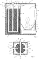
- Fig. 1 illustrates a first embodiment of a heat generator 1 of the present invention.
- a heat generator for example, a boiler or oven
- this includes a combustion device, a latent heat storage and a combustion gas guide.
- the combustion device is designed for the combustion of different solid fuels.
- Solid fuels may be: briquettes made of wood / coal, logs, pellets, wood chips or another type of (solid) combustible biomass.
- the combustion device typically includes a combustion chamber in which the fuel burns and - depending on the type of fuel - for example. a catch tank for combustion residues.
- the combustion device includes combustion gas fans and / or air supply fans known to those skilled in the art, and the like. Since the combustion device is within the skill of the art, further description of known combustion devices will be omitted.
- the heat generator is firewood and / or pellet stoves, which are typically installed in a living space.
- the combustion device When combusting corresponding fuels, the combustion device generates a combustion gas which partially guides the combustion gas duct through the latent heat accumulator.
- the combustion gas contains a certain amount of heat that it can deliver at least partially to the latent heat storage at its flow.
- the combustion gas duct passes through a heat exchanger which delivers the heat of the combustion gas to the heat storage material of the latent heat storage.
- the combustion gas guide is quasi itself the heat exchanger, since, for example.
- the combustion gas is guided by means of a pipeline through the latent heat storage and the heat storage material has direct contact with the combustion gas guide through which the combustion gas flows.
- the heat of the combustion gas then passes through the combustion gas guide, ie their lines, in the heat storage material and heats it up.
- the combustion gas is split, so that it is passed through the latent heat storage in several ways and thereby a uniform Charging (heating) of the latent heat storage allows.
- the heat exchanger is designed such that it allows a uniform distribution of the heat in the latent heat storage or its heat storage material.
- the heat exchanger on a large surface of a material, such as, graphite foils, which has a good heat conducting property. This heat-conducting material is uniformly distributed in the latent heat storage and is in both thermally conductive contact with the combustion gas guide and the heat storage material.
- the heat generator on an air duct is guided through the air to be heated.
- the heat exchange is then configured so that it is in heat-conducting contact with the heat storage material, the air guide and the combustion gas guide.
- the heat storage material is in the latent heat storage, eg. In a container.
- the heat storage material is a latent heat storage material that stores corresponding latent heat, which is always free or must be supplied when a material performs a so-called phase transition.
- the phase transition is, for example, from solid to liquid and vice versa.
- the heat storage material is solid and, for example, powdered. Such a powdery material is in the ground state, ie at room temperature, powdery and liquefies, ie it changes from the solid to the liquid phase state when a certain temperature, namely the melting temperature is exceeded.
- the heat storage material has a melting point that is in the range between 200 ° C and 400 ° C - that is, the temperature range that also typically has the combustion gas.
- Some heat storage materials assume a smaller volume in the molten state, ie in the liquid phase, than in the solid (powdery) state. As a result, there is no danger of such materials "spilling out” of the container in which they are located if the occupied volume becomes too large, ie greater than the container volume.
- Other heat storage materials increase their volume in the liquid phase. Therefore, in such heat storage materials of the container in which the heat storage material is not completely filled, but at least that takes place during the phase transition from solid to liquid volume change considered during the filling of the container.
- salt hydrates are used as heat storage materials in some embodiments.
- nitrate or nitrite salts with a matrix material such as graphite (expanded graphite or natural graphite) can be used.
- Expanded graphite which is powdery, can be pressed with these salts, whereby a powdered heat storage material is formed.
- salts used are LiNO 3 having a melting point of 254 ° C., NaNO 2 having a melting point of 270 ° C. or NaNO 3 having a melting point of 306 ° C.
- the corresponding latent heat of these materials is in the range of about 60 W / mK.
- the container in which the heat storage material is, in some embodiments of metal, for example.
- a corrosion-resistant or Pochfrrienbe residue residue metal such as stainless steel, for example. With a molybdenum content. If the container is almost airtight, normal steel is sufficient as a container material, since in this case no additional oxygen enters the container and thus corrosion is prevented.
- the latent heat storage is connected directly to the combustion device, both are located for example in a housing. In other embodiments, the latent heat storage, however, is separated from the combustion device and, for example, connected only via the combustion gas guide with the combustion device. That is, in some embodiments, the latent heat storage may reside in another room, e.g. in the basement, as the incinerator, which is arranged, for example, in the living room.
- the latent heat storage device can release its stored heat in some embodiments in air, which flows through a heat exchanger, for example.
- the heat exchanger is, for example, arranged within the latent heat accumulator so that it can absorb heat from the heat storage material and deliver it to air flowing through the heat exchanger.
- an air guide is part of the heat exchanger, the room air through the latent heat storage and as a result, by the heat storage material to flow.
- the heat exchanger has an extra device, which includes, for example, turbulators, which are arranged within the latent heat accumulator and throttle the air flow, so that an improved heat transfer to the air can take place.
- the heat generator for example, an air control means, which is mechanically or electrically operable.
- the air control means is adapted to control the amount of air by, for example, the flow cross-section through which the amount of air flows changed.
- the air is, for example, room air, which is taken from a room flows through the latent heat storage or the heat exchanger and heated back to the room is returned. By controlling the amount of air is consequently also the heat emitted per time and thus, for example. Also controlled a room temperature.
- the heat generator further comprises a heat exchanger, which is adapted to at least partially deliver heat from combustion gases to (room) air flowing through it.
- the heat exchanger is, for example, disposed within or above the combustion chamber of the combustion device.
- the heat exchanger comprises areas or openings through which the combustion gas flows and areas or openings through which air or room air flows.
- the heat exchanger is designed to deliver the heat of the combustion gases to the air so that, for example, a room in which the heat generator is located can also be heated by the air heated in the heat exchanger (and not only by the heat generator emitted radiant heat).
- Some heat generators further comprise a mechanically and / or electrically operable switching means, which is designed to allow combustion gases in the combustion gas flow to flow either through the latent heat accumulator or the aforementioned heat exchanger or partly through both. That In such heat generators can, for example, before the latent heat storage is "charged” with heat, first the space in which the heat generator is located to be warmed up quickly by the warming of the air in the aforementioned heat exchanger.
- the heat generator further comprises an electrical control.
- the electrical control is, for example, designed to control the switching means as a function of an input variable.
- an input variable is, for example, the room temperature, so that at a low room temperature, which is below a setpoint, the space is first heated quickly by the switching means is set so that the combustion gas flows through the aforementioned heat exchanger. If the desired room temperature, ie the target value is reached, the controller sets the switching means so that the combustion gas flows through the latent heat accumulator and charges it by appropriate heat dissipation.
- the controller may be further configured to control the air medium. That the controller may control whether heated air is to flow into the room or not, depending on an input quantity (e.g., the room temperature), by controlling the air control means so that the air flows through the latent heat storage and is heated.
- the controller is designed for additional control functions, as are common in the field of heat generators and known to those skilled in the art.
- Some embodiments relate to a latent heat storage for a heat generator (as described above), wherein the latent heat storage comprises a heat storage material which is powdery and has a melting point in the range between 200 ° C and 400 ° C.
- FIG. 1 is there a first embodiment of a heat generator 1 illustrated.
- the heat generator 1 here for example a log firing furnace, has a combustion device 2 and a latent heat accumulator 5.
- a combustion device 2 having a combustion chamber which can be opened and closed by an oven door 11, located in a combustion bowl 7, which has a grate 8, a billet 9.
- This firewood burns in the incinerator 2 and combustion residues fall through the grate 8 in a so-called Ash Tray 10.
- Combustion gases which are produced during the combustion of the billet 9 in the combustion device 2 flow into the combustion chamber of the combustion device 2 above and pass through the opening 15 of a combustion gas guide 37 in a first portion 12 of the combustion gas guide 37th
- the combustion gas guide 37 in this exemplary embodiment represents a continuous ducting system which has a first section 12 which extends from the combustion chamber of the combustion device 2 into the space 3 of the latent heat accumulator 5.
- the tube section 12 bends at its end by 90 ° and merges into a vertical section 23, which is already in the latent heat accumulator 5, and passes through a heat storage material 6, which is located in the latent heat accumulator 5.
- the heat storage material 6 is shown here obliquely hatched.
- the combustion gas duct further has a lower portion 19, which then merges into a vertical portion 22 by a further 90 ° bend and at the end after another 90 degree bend in an end portion 18.
- the combustion gas which absorbs its heat the way through the latent heat storage 5 has given to the heat storage material 6, through the opening 16.
- At this opening 16 is, for example, a chimney connection, through which the combustion gas is discharged to the environment.
- the air control means 14 is configured as an electrically operable device, which can change the air cross-section of completely open, that is, the entire pipe cross-section of the tube 13 until completely closed.
- the air duct 38 further pipe sections on, which are similar to the pipe section 13.
- the air in this case the ambient air surrounding the heat generator 1, enters the pipe section 20 of the air duct 38 at an opening 21, the section 20 being arranged at a lower end of the heat generator.
- This lower tube section 20 extends almost through the entire latent heat accumulator 5, that is, it extends substantially to the upwardly extending tube, which is the uppermost circular cross-section with the reference numeral 27 in the Fig. 2 is shown.
- the tube 20 has connections to the vertically extending pipe sections of the air guide 38, which are indicated by reference numbers 24, 25, 26 and 27 Fig. 1 only a vertically extending pipe section 13 is shown, whereas the Fig. 2 all perpendicular pipe sections with the reference numerals 24, 25, 26 and 27 shows.
- the air which passes through the opening 21 in the lower tube section 20, thus flows through the respective vertical sections 24, 25, 26 and 27 of the air guide 38 through the latent heat accumulator 5 from bottom to top and is above by another pipe section, the here not shown, collected and directed to the opening 17, through the air control means 14 therethrough.
- the air flow is due solely to convection, which is caused by the different heating of the different pipe sections and thus the air contained therein.
- the arranged in the upper edge region of the heat generator 1 opening 17 then flows the heated air which has been heated by the heat output from the heat storage material 6, for example in the room in which the heat generator 1 is arranged.
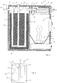
- FIG. 2 a portion of the combustion gas guide 37 shown.
- Fig. 2 shows the pipe section 12 which extends from the combustion device 2 in the space 3 and the vertical tube 23, which is shown here only in its circular cross-section.
- the vertical section 22 of the combustion gas guide 37 On the left side of the Fig. 2 one sees the vertical section 22 of the combustion gas guide 37 and further the corresponding section 18, which extends out of the latent heat accumulator 5 out.
- the opening 16 enters the combustion gas, which has occurred on the right side at the opening 15, again.
- a heat storage material 6 is in this embodiment, a material with high Heat storage capacity and provided with a melting point in the range of 270 ° C, in which case in the special case was used as a powdery material NaNO 2 with expanded graphite as a matrix material.
- the heat storage material 6 stores the excess heat from the combustion device by dissipating heat from the combustion gas as latent heat latent for melting the heat storage material 6.
- the air control means 14 can be operated so that the room air flows through the air guide 38 and at a later heating demand so the room can be heated with appropriately heated air.
- Fig. 3 shows a second embodiment of the heat generator 1, wherein the heat generator 1 of the after Fig. 1 essentially only differs in that it additionally has a heat exchanger 33 and corresponding room air inlet and outlet openings 31.
- the parts of the heat generator 1 after Fig. 3 following the parts of the heat generator Fig. 1 are provided with the same reference numerals for the sake of simplicity and they have the same characteristics as described above in connection with the first embodiment.
- the heat exchanger 33 serves to achieve a rapid heat transfer to the space surrounding the heat generator 1 after starting up the heat generator 1 even when the accumulator 5 is unloaded.
- the heat exchanger 33 can be warmed up directly with the combustion gases produced in the combustion chamber, and the heat emitted there is emitted directly to the room air flowing into the heat exchanger 33 through openings 31.
- the heat exchanger 33 has a piping system 32 through which the incoming through the opening 30 combustion gas is passed. In the remaining areas designated by 28 of the heat generator 33, room air which flows in through openings 31 can now be heated and also flow out there again.
- a switching means 29 is further arranged, which-as required - the combustion gas can flow either through the heat exchanger 33 or through the latent heat storage 5.
- the switching means 29 is electrically formed here, but can also mechanically, for example as a slide, be educated.
- a controller 34 is provided.
- the controller 34 is disposed in the heat generator 1 at any suitable location and is connected via lines 35 and 36 to the air control means 14 and the switching means 29. In some embodiments, the controller is also outside the heat generator.
- the controller is here designed to control the corresponding means to be controlled, depending on the room temperature at which the heat generator is located, such as here the air control means 14 and the switching means 29.
- a control scheme is as follows: Assuming the room temperature is below a set value of, for example, 21 ° C and the heat generator is being put into operation, i. the latent memory 5 is not charged. The controller is then configured to close the air control means 14 and to set the switching means 29 to flow the combustion gas passing through the opening into the heat exchanger 33 through the serpentine guide 32. As a result, the air that passes through the openings 31 in the heat exchanger 33, heated quickly and it flows immediately as warm air back into the room. Once the setpoint of 21 ° C is reached, the controller controls the switching means 29 so that the combustion gas no longer passes through the heat exchanger 33, but flows through the latent heat accumulator 5 through the pipe sections 12, 23, 19, 22 and 18.
- the heat storage material 6 is heated in the latent heat storage 5.
- the air control means 14 remains closed. Should now, at a later time, for example, when the firewood 9 is already burned, the room temperature again fall below the setpoint of 21 ° C, the controller 34 controls the air control means 14 so that it is open and thus heated air passing through the latent heat storage 5 has been heated, in turn is delivered to the room.
- the Fig. 5 to 9 illustrate a further embodiment of a latent heat storage 5 ', for example, in a heat generator 1 after the Fig. 1 to 3 can be installed.
- the latent heat store 5 ' essentially has a combustion gas guide 37', an air guide 38 'and a heat exchanger 39.
- the combustion gas guide 37 ' has in the latent heat storage 5' five combustion gas pipes 46 to 50 (see Fig. 7 ), which are guided vertically, ie from bottom to top, through the latent heat accumulator 5 'and have a tubular cross-section.
- the combustion gas tubes 46-50 are in a plan view ( Fig. 7 ) as the number five arranged on a cube and heat through this distribution in the latent heat storage 5 'the heat storage material 6' therein as evenly as possible.
- Combustion gas passes, for example, through a connection pipe 60 (FIG. Fig. 8, 9 ) in a lower portion 62 of the latent heat storage 5 '.
- the combustion gas is divided and flows due to convection through the individual combustion gas pipes 46-50 through the latent heat storage 5 'upwards and reaches a region 61. From the area 61 then passes the combustion gas through an upper connecting pipe 59, to the outside.
- the air guide 38 ' has four air pipes 41 to 44, which are also vertically, ie guided from bottom to top by the latent heat storage 5'. These air pipes 41 have a rectangular cross-section, such as. In Fig. 7 is shown.
- the air pipes 41 to 44 are longer than the combustion gas pipes 46 to 50 so that they do not end in the areas 61 and 62, since otherwise combustion gas could get into the air duct 38 '.
- the combustion gas pipes 46 to 50 and the air pipes 41 to 44 are guided on their way from bottom to top through the heat exchanger 39.
- the heat exchanger 39 comprises a plurality of retaining plates 40 on each of which a graphite foil is attached.
- the holding plates 40 and the graphite foils thereon have the same hole pattern, such as.
- the upper end plate 45, the in Fig. 7 is shown. That is, both the combustion gas tubes 46 to 50 and the air tubes 41 to 44 extend through each individual retaining plate 40 and thus also through respective graphite foil.
- the graphite foils have very good heat-conducting properties, and conduct the heat that the combustion gas emits on its way through the heat exchanger 39, into the interior of the latent heat accumulator 5 'and thereby charge the heat storage material 6', which is located between the holding plates 40 on. Due to the "rib-like" arrangement of the holding plates 40 with the graphite foils thereon, the heat given off to them is distributed as evenly as possible in the latent heat store 5 'and in the heat storage material 6' located therein.
- the holding plates 40 are held by inclined portions 52 and 53 and the dimensions of the individual holding plates 40 are selected so that they are evenly spaced by the tapered portions 52 and 53 are held.
- the retaining plates 40 can be so easily inserted in a corresponding order in the limited space by areas 52 and 53 space.
- the areas 52 and 53 are shown here only for two sides of the latent heat storage 5 '. On the two sides not shown are similar beveled areas, so that the retaining plates 40 are held on their four sides.
- the complex of heat exchanger 39 is limited with the intermediate heat storage material 6 'above and below by an upper end plate 45 and below by a lower end plate 51, both of which each have a hole pattern, as it is for the upper end plate 45 in Fig. 7 is shown.
- the end plates 45 and 51 also serve to secure the pipes of the air duct 38 'and those of the combustion duct 37'.
- the latent heat storage 5 'top and bottom closed above and the upper and lower ends of the latent heat accumulator 5' form together with the upper and lower end plates 45 and 51, the upper portion 61 and the lower portion 62 through the combustion gas and split into the combustion gas pipes 46 to 50.
- the air pipes 41 to 44 pass through the complete latent heat accumulator 5 'in a vertical direction, so that, for example, room air can flow through the latent heat accumulator 5'.
- the heat exchanger 39 thus performs a dual function, since it not only conducts the heat from the combustion gas into the latent heat storage 5 'and the heat storage material 6' therein, but the heat exchanger also conducts heat from the latent heat storage 5 'to the air pipes 41 to 44 the air guide 38 ', which heats up through the air duct 38' and in particular through the air pipes 41 to 44 flowing air.
- an air slide 14 ' is arranged on the latent heat accumulator 5' ( 8 and 9 ).
- the air slide 14 ' has rectangular openings 57 and circular openings 58.
- the entire air slide 14' can be rotated, whereby, for example, the rectangular openings 57 above the air pipes 41 to 44 can be arranged accordingly.
- the latent heat storage 5 ' additionalally has a thermal insulation, in the sectional view Fig. 8 can be seen in the areas 54 and 55, so that the heat in the heat storage material 6 'of the latent heat storage 5' remains and a controlled heat transfer with the air valve 14 'is possible.
- the heat insulation 54, 55 surrounds the heat exchanger 39 and the heat storage material 6 'on the sides and partly also up and down, in order to achieve the best possible thermal insulation.
- the latent heat storage 5 ' is thus designed so that it gives little or no heat in the form of heat radiation, but gives off its stored heat in the form of warmed (room) air. As a result, a targeted heat indication is possible.
Landscapes
- Engineering & Computer Science (AREA)
- Physics & Mathematics (AREA)
- Thermal Sciences (AREA)
- Chemical & Material Sciences (AREA)
- Combustion & Propulsion (AREA)
- Mechanical Engineering (AREA)
- General Engineering & Computer Science (AREA)
- Solid-Fuel Combustion (AREA)
- Air Supply (AREA)
- Thermotherapy And Cooling Therapy Devices (AREA)
- Central Heating Systems (AREA)
Claims (8)
- Générateur de chaleur, comprenant :un dispositif de combustion (2),un accumulateur de chaleur latente (5, 5'),un échangeur thermique (33), qui est conçu pour céder de la chaleur des gaz de combustion au moins en partie à l'air le traversant, etun guide de gaz de combustion (37, 37'), dans lequel le guide de gaz de combustion (37, 37') est amené au moins en partie à travers l'accumulateur de chaleur latente (5, 5') de telle sorte que la chaleur du gaz de combustion guidé dans le guide de gaz de combustion (37, 37') est cédée au moins en partie au matériau d'accumulation de chaleur (6, 6') dans l'accumulateur de chaleur latente (5, 5'),
caractérisé en ce quele générateur de chaleur est conçu pour des combustibles solides et est réalisé sous forme de poêle à bois de chauffage et/ou à pellets, etun moyen de commutation (29) est conçu pour laisser s'écouler des gaz de combustion dans le guide de gaz de combustion (37) à travers l'accumulateur de chaleur latente et/ou l'échangeur thermique (33), dans lequel une commande électrique (34) est prévue pour la commande du moyen de commutation (29) en fonction d'une grandeur d'entrée. - Générateur de chaleur selon l'une quelconque des revendications précédentes, dans lequel le matériau d'accumulation de chaleur (6, 6') présente un point de fusion dans la plage entre 200 °C et 400 °C.
- Générateur de chaleur selon l'une quelconque des revendications précédentes, dans lequel le matériau d'accumulation de chaleur (6, 6') occupe à l'état fondu un plus petit volume qu'à l'état solide.
- Générateur de chaleur selon l'une quelconque des revendications précédentes, dans lequel l'accumulateur de chaleur latente (5, 5') comprend un récipient en acier inoxydable.
- Générateur de chaleur selon l'une quelconque des revendications précédentes, dans lequel l'accumulateur de chaleur latente (5, 5') est séparé du dispositif de combustion (2).
- Générateur de chaleur selon l'une quelconque des revendications précédentes, dans lequel l'accumulateur de chaleur latente (5, 5') présente en outre un autre échangeur thermique (38, 39) pour céder de la chaleur du matériau d'accumulation de chaleur (6, 6') à l'air qui s'écoule à travers l'autre échangeur thermique (38, 39).
- Générateur de chaleur selon la revendication 6, dans lequel l'autre échangeur thermique (38, 39) est conçu de façon à ce qu'il soit en contact de conduction thermique avec le matériau d'accumulation de chaleur (6'), le guide de gaz de combustion (37') et un guide d'air (38'), à travers lesquels l'air à chauffer s'écoule.
- Générateur de chaleur selon la revendication 7, présentant en outre un moyen de commande d'air (14, 14'), qui est conçu pour commander le volume d'air s'écoulant à travers l'autre échangeur thermique (38, 39).
Applications Claiming Priority (1)
| Application Number | Priority Date | Filing Date | Title |
|---|---|---|---|
| DE200810057911 DE102008057911B4 (de) | 2008-11-18 | 2008-11-18 | Latentspeicherofen |
Publications (3)
| Publication Number | Publication Date |
|---|---|
| EP2187145A2 EP2187145A2 (fr) | 2010-05-19 |
| EP2187145A3 EP2187145A3 (fr) | 2015-04-29 |
| EP2187145B1 true EP2187145B1 (fr) | 2017-03-15 |
Family
ID=41319690
Family Applications (1)
| Application Number | Title | Priority Date | Filing Date |
|---|---|---|---|
| EP09012106.2A Not-in-force EP2187145B1 (fr) | 2008-11-18 | 2009-09-23 | Poêle à accumulation latent |
Country Status (2)
| Country | Link |
|---|---|
| EP (1) | EP2187145B1 (fr) |
| DE (1) | DE102008057911B4 (fr) |
Families Citing this family (5)
| Publication number | Priority date | Publication date | Assignee | Title |
|---|---|---|---|---|
| AT510838B1 (de) * | 2011-03-14 | 2012-07-15 | Riener Karl Stefan | Heizeinrichtung mit einem brennraum zur verbrennung von brennmaterial auf basis von biomasse |
| CN102261741B (zh) * | 2011-08-03 | 2013-04-03 | 无锡锡能锅炉有限公司 | 模块式结构的有机热载体锅炉 |
| DE102013019954A1 (de) | 2013-11-27 | 2015-05-28 | Karl Stefan Riener | Ofen zur Wärmeerzeugung |
| CN106931642A (zh) * | 2015-12-30 | 2017-07-07 | 沈阳兰昊新能源科技有限公司 | 生物质燃料蓄热式热风锅炉 |
| DE102023117983A1 (de) * | 2023-07-07 | 2025-01-09 | Hochschule Anhalt, Körperschaft des öffentlichen Rechts | Vorrichtung zur Wärmerückgewinnung und Rückführung, sowie deren Verwendung |
Family Cites Families (3)
| Publication number | Priority date | Publication date | Assignee | Title |
|---|---|---|---|---|
| US4250866A (en) * | 1979-09-10 | 1981-02-17 | Research Institute For Advanced Technology | Thermal energy storage to increase furnace efficiency |
| JPS5838708B2 (ja) * | 1981-03-06 | 1983-08-24 | 工業技術院長 | 太陽熱集熱器 |
| DE102007046133B4 (de) * | 2007-05-04 | 2011-05-05 | Jess Gmbh | Wärmespeicher zur Speicherung von Energie |
-
2008
- 2008-11-18 DE DE200810057911 patent/DE102008057911B4/de not_active Expired - Fee Related
-
2009
- 2009-09-23 EP EP09012106.2A patent/EP2187145B1/fr not_active Not-in-force
Non-Patent Citations (1)
| Title |
|---|
| None * |
Also Published As
| Publication number | Publication date |
|---|---|
| EP2187145A2 (fr) | 2010-05-19 |
| EP2187145A3 (fr) | 2015-04-29 |
| DE102008057911A1 (de) | 2010-05-20 |
| DE102008057911B4 (de) | 2013-08-29 |
Similar Documents
| Publication | Publication Date | Title |
|---|---|---|
| EP2187145B1 (fr) | Poêle à accumulation latent | |
| DE29824684U1 (de) | Heizofen, insbesondere mit Gas und/oder Ölfeuerung | |
| EP2339246A2 (fr) | Agencement pour fournil doté d'une récupération de chaleur | |
| DE19806257A1 (de) | Ofen für die Verbrennung von Pellets | |
| EP2045528B1 (fr) | Système d'accumulation de chaleur | |
| DE20220234U1 (de) | Holzbackofen | |
| EP2878895B1 (fr) | Four de production de chaleur | |
| WO1997041395A1 (fr) | Systeme de chauffage basse temperature | |
| DE102008011167A1 (de) | Heizofen zum Beheizen des Raumes eines Wohn-Gebäudes | |
| DE102008035407A1 (de) | Wärmetauscher | |
| EP0082306B1 (fr) | Installation de chauffage locale | |
| AT411390B (de) | Heizeinsatz für biogene brennstoffe mit integriertem feststoffspeicher und heizungswärmetauscher | |
| DE2653973A1 (de) | Heizaggregat fuer warmwasserheizung | |
| DE202009004942U1 (de) | Grundofenanordnung mit einem Wärmetauscher | |
| DE202014101251U1 (de) | Offener Kamin mit eingesetzter Kaminkassette | |
| DE10100678B4 (de) | Heizungssystem | |
| DE102007032093A1 (de) | Grundofen mit Wärmetauschermodulen | |
| AT411793B (de) | Heizeinsatz | |
| DE2934721A1 (de) | Wechselbrandkessel. | |
| DE908185C (de) | Heizofen mit Fuellschacht | |
| DE3004601A1 (de) | Durchbrandofen | |
| DE102015014340B3 (de) | Heizsystem | |
| DE102013005970A1 (de) | Wärmesystem, Wärmesystem mit einem Kaminofen, Anordnung eines Wärmesystems und Verfahren zum Betreiben eines gebäudeinstallierten Wärmesystems | |
| DE23874C (de) | Neuerungen an Oefen mit Füllschachtfeuerungen | |
| CH626153A5 (en) | Heating aggregate for hot-water heating systems |
Legal Events
| Date | Code | Title | Description |
|---|---|---|---|
| PUAI | Public reference made under article 153(3) epc to a published international application that has entered the european phase |
Free format text: ORIGINAL CODE: 0009012 |
|
| AK | Designated contracting states |
Kind code of ref document: A2 Designated state(s): AT BE BG CH CY CZ DE DK EE ES FI FR GB GR HR HU IE IS IT LI LT LU LV MC MK MT NL NO PL PT RO SE SI SK SM TR |
|
| AX | Request for extension of the european patent |
Extension state: AL BA RS |
|
| RIC1 | Information provided on ipc code assigned before grant |
Ipc: F24H 7/04 20060101ALI20141211BHEP Ipc: F24H 3/08 20060101AFI20141211BHEP |
|
| PUAL | Search report despatched |
Free format text: ORIGINAL CODE: 0009013 |
|
| AK | Designated contracting states |
Kind code of ref document: A3 Designated state(s): AT BE BG CH CY CZ DE DK EE ES FI FR GB GR HR HU IE IS IT LI LT LU LV MC MK MT NL NO PL PT RO SE SI SK SM TR |
|
| AX | Request for extension of the european patent |
Extension state: AL BA RS |
|
| RIC1 | Information provided on ipc code assigned before grant |
Ipc: F24H 7/04 20060101ALI20150325BHEP Ipc: F24H 3/08 20060101AFI20150325BHEP |
|
| 17P | Request for examination filed |
Effective date: 20151026 |
|
| RBV | Designated contracting states (corrected) |
Designated state(s): AT BE BG CH CY CZ DE DK EE ES FI FR GB GR HR HU IE IS IT LI LT LU LV MC MK MT NL NO PL PT RO SE SI SK SM TR |
|
| 17Q | First examination report despatched |
Effective date: 20160407 |
|
| GRAP | Despatch of communication of intention to grant a patent |
Free format text: ORIGINAL CODE: EPIDOSNIGR1 |
|
| INTG | Intention to grant announced |
Effective date: 20160921 |
|
| GRAS | Grant fee paid |
Free format text: ORIGINAL CODE: EPIDOSNIGR3 |
|
| GRAA | (expected) grant |
Free format text: ORIGINAL CODE: 0009210 |
|
| AK | Designated contracting states |
Kind code of ref document: B1 Designated state(s): AT BE BG CH CY CZ DE DK EE ES FI FR GB GR HR HU IE IS IT LI LT LU LV MC MK MT NL NO PL PT RO SE SI SK SM TR |
|
| REG | Reference to a national code |
Ref country code: CH Ref legal event code: EP Ref country code: GB Ref legal event code: FG4D Free format text: NOT ENGLISH |
|
| REG | Reference to a national code |
Ref country code: IE Ref legal event code: FG4D Free format text: LANGUAGE OF EP DOCUMENT: GERMAN |
|
| REG | Reference to a national code |
Ref country code: AT Ref legal event code: REF Ref document number: 875992 Country of ref document: AT Kind code of ref document: T Effective date: 20170415 |
|
| REG | Reference to a national code |
Ref country code: DE Ref legal event code: R096 Ref document number: 502009013739 Country of ref document: DE |
|
| REG | Reference to a national code |
Ref country code: NL Ref legal event code: MP Effective date: 20170315 |
|
| REG | Reference to a national code |
Ref country code: LT Ref legal event code: MG4D |
|
| PG25 | Lapsed in a contracting state [announced via postgrant information from national office to epo] |
Ref country code: LT Free format text: LAPSE BECAUSE OF FAILURE TO SUBMIT A TRANSLATION OF THE DESCRIPTION OR TO PAY THE FEE WITHIN THE PRESCRIBED TIME-LIMIT Effective date: 20170315 Ref country code: GR Free format text: LAPSE BECAUSE OF FAILURE TO SUBMIT A TRANSLATION OF THE DESCRIPTION OR TO PAY THE FEE WITHIN THE PRESCRIBED TIME-LIMIT Effective date: 20170616 Ref country code: FI Free format text: LAPSE BECAUSE OF FAILURE TO SUBMIT A TRANSLATION OF THE DESCRIPTION OR TO PAY THE FEE WITHIN THE PRESCRIBED TIME-LIMIT Effective date: 20170315 Ref country code: HR Free format text: LAPSE BECAUSE OF FAILURE TO SUBMIT A TRANSLATION OF THE DESCRIPTION OR TO PAY THE FEE WITHIN THE PRESCRIBED TIME-LIMIT Effective date: 20170315 Ref country code: NO Free format text: LAPSE BECAUSE OF FAILURE TO SUBMIT A TRANSLATION OF THE DESCRIPTION OR TO PAY THE FEE WITHIN THE PRESCRIBED TIME-LIMIT Effective date: 20170615 |
|
| PG25 | Lapsed in a contracting state [announced via postgrant information from national office to epo] |
Ref country code: LV Free format text: LAPSE BECAUSE OF FAILURE TO SUBMIT A TRANSLATION OF THE DESCRIPTION OR TO PAY THE FEE WITHIN THE PRESCRIBED TIME-LIMIT Effective date: 20170315 Ref country code: BG Free format text: LAPSE BECAUSE OF FAILURE TO SUBMIT A TRANSLATION OF THE DESCRIPTION OR TO PAY THE FEE WITHIN THE PRESCRIBED TIME-LIMIT Effective date: 20170615 Ref country code: SE Free format text: LAPSE BECAUSE OF FAILURE TO SUBMIT A TRANSLATION OF THE DESCRIPTION OR TO PAY THE FEE WITHIN THE PRESCRIBED TIME-LIMIT Effective date: 20170315 |
|
| PG25 | Lapsed in a contracting state [announced via postgrant information from national office to epo] |
Ref country code: NL Free format text: LAPSE BECAUSE OF FAILURE TO SUBMIT A TRANSLATION OF THE DESCRIPTION OR TO PAY THE FEE WITHIN THE PRESCRIBED TIME-LIMIT Effective date: 20170315 |
|
| PG25 | Lapsed in a contracting state [announced via postgrant information from national office to epo] |
Ref country code: CZ Free format text: LAPSE BECAUSE OF FAILURE TO SUBMIT A TRANSLATION OF THE DESCRIPTION OR TO PAY THE FEE WITHIN THE PRESCRIBED TIME-LIMIT Effective date: 20170315 Ref country code: IT Free format text: LAPSE BECAUSE OF FAILURE TO SUBMIT A TRANSLATION OF THE DESCRIPTION OR TO PAY THE FEE WITHIN THE PRESCRIBED TIME-LIMIT Effective date: 20170315 Ref country code: SK Free format text: LAPSE BECAUSE OF FAILURE TO SUBMIT A TRANSLATION OF THE DESCRIPTION OR TO PAY THE FEE WITHIN THE PRESCRIBED TIME-LIMIT Effective date: 20170315 Ref country code: RO Free format text: LAPSE BECAUSE OF FAILURE TO SUBMIT A TRANSLATION OF THE DESCRIPTION OR TO PAY THE FEE WITHIN THE PRESCRIBED TIME-LIMIT Effective date: 20170315 Ref country code: EE Free format text: LAPSE BECAUSE OF FAILURE TO SUBMIT A TRANSLATION OF THE DESCRIPTION OR TO PAY THE FEE WITHIN THE PRESCRIBED TIME-LIMIT Effective date: 20170315 Ref country code: ES Free format text: LAPSE BECAUSE OF FAILURE TO SUBMIT A TRANSLATION OF THE DESCRIPTION OR TO PAY THE FEE WITHIN THE PRESCRIBED TIME-LIMIT Effective date: 20170315 |
|
| PG25 | Lapsed in a contracting state [announced via postgrant information from national office to epo] |
Ref country code: IS Free format text: LAPSE BECAUSE OF FAILURE TO SUBMIT A TRANSLATION OF THE DESCRIPTION OR TO PAY THE FEE WITHIN THE PRESCRIBED TIME-LIMIT Effective date: 20170715 Ref country code: PT Free format text: LAPSE BECAUSE OF FAILURE TO SUBMIT A TRANSLATION OF THE DESCRIPTION OR TO PAY THE FEE WITHIN THE PRESCRIBED TIME-LIMIT Effective date: 20170717 Ref country code: PL Free format text: LAPSE BECAUSE OF FAILURE TO SUBMIT A TRANSLATION OF THE DESCRIPTION OR TO PAY THE FEE WITHIN THE PRESCRIBED TIME-LIMIT Effective date: 20170315 Ref country code: SM Free format text: LAPSE BECAUSE OF FAILURE TO SUBMIT A TRANSLATION OF THE DESCRIPTION OR TO PAY THE FEE WITHIN THE PRESCRIBED TIME-LIMIT Effective date: 20170315 |
|
| PGFP | Annual fee paid to national office [announced via postgrant information from national office to epo] |
Ref country code: AT Payment date: 20170928 Year of fee payment: 9 |
|
| REG | Reference to a national code |
Ref country code: DE Ref legal event code: R097 Ref document number: 502009013739 Country of ref document: DE |
|
| PLBE | No opposition filed within time limit |
Free format text: ORIGINAL CODE: 0009261 |
|
| STAA | Information on the status of an ep patent application or granted ep patent |
Free format text: STATUS: NO OPPOSITION FILED WITHIN TIME LIMIT |
|
| PG25 | Lapsed in a contracting state [announced via postgrant information from national office to epo] |
Ref country code: DK Free format text: LAPSE BECAUSE OF FAILURE TO SUBMIT A TRANSLATION OF THE DESCRIPTION OR TO PAY THE FEE WITHIN THE PRESCRIBED TIME-LIMIT Effective date: 20170315 |
|
| 26N | No opposition filed |
Effective date: 20171218 |
|
| PG25 | Lapsed in a contracting state [announced via postgrant information from national office to epo] |
Ref country code: SI Free format text: LAPSE BECAUSE OF FAILURE TO SUBMIT A TRANSLATION OF THE DESCRIPTION OR TO PAY THE FEE WITHIN THE PRESCRIBED TIME-LIMIT Effective date: 20170315 |
|
| REG | Reference to a national code |
Ref country code: CH Ref legal event code: PL |
|
| GBPC | Gb: european patent ceased through non-payment of renewal fee |
Effective date: 20170923 |
|
| PG25 | Lapsed in a contracting state [announced via postgrant information from national office to epo] |
Ref country code: MC Free format text: LAPSE BECAUSE OF FAILURE TO SUBMIT A TRANSLATION OF THE DESCRIPTION OR TO PAY THE FEE WITHIN THE PRESCRIBED TIME-LIMIT Effective date: 20170315 |
|
| REG | Reference to a national code |
Ref country code: IE Ref legal event code: MM4A |
|
| REG | Reference to a national code |
Ref country code: BE Ref legal event code: MM Effective date: 20170930 |
|
| PG25 | Lapsed in a contracting state [announced via postgrant information from national office to epo] |
Ref country code: LU Free format text: LAPSE BECAUSE OF NON-PAYMENT OF DUE FEES Effective date: 20170923 |
|
| REG | Reference to a national code |
Ref country code: FR Ref legal event code: ST Effective date: 20180531 |
|
| PG25 | Lapsed in a contracting state [announced via postgrant information from national office to epo] |
Ref country code: GB Free format text: LAPSE BECAUSE OF NON-PAYMENT OF DUE FEES Effective date: 20170923 Ref country code: IE Free format text: LAPSE BECAUSE OF NON-PAYMENT OF DUE FEES Effective date: 20170923 Ref country code: CH Free format text: LAPSE BECAUSE OF NON-PAYMENT OF DUE FEES Effective date: 20170930 Ref country code: LI Free format text: LAPSE BECAUSE OF NON-PAYMENT OF DUE FEES Effective date: 20170930 |
|
| PG25 | Lapsed in a contracting state [announced via postgrant information from national office to epo] |
Ref country code: BE Free format text: LAPSE BECAUSE OF NON-PAYMENT OF DUE FEES Effective date: 20170930 Ref country code: FR Free format text: LAPSE BECAUSE OF NON-PAYMENT OF DUE FEES Effective date: 20171002 |
|
| PG25 | Lapsed in a contracting state [announced via postgrant information from national office to epo] |
Ref country code: MT Free format text: LAPSE BECAUSE OF FAILURE TO SUBMIT A TRANSLATION OF THE DESCRIPTION OR TO PAY THE FEE WITHIN THE PRESCRIBED TIME-LIMIT Effective date: 20170315 |
|
| REG | Reference to a national code |
Ref country code: AT Ref legal event code: MM01 Ref document number: 875992 Country of ref document: AT Kind code of ref document: T Effective date: 20180923 |
|
| PG25 | Lapsed in a contracting state [announced via postgrant information from national office to epo] |
Ref country code: HU Free format text: LAPSE BECAUSE OF FAILURE TO SUBMIT A TRANSLATION OF THE DESCRIPTION OR TO PAY THE FEE WITHIN THE PRESCRIBED TIME-LIMIT; INVALID AB INITIO Effective date: 20090923 |
|
| PG25 | Lapsed in a contracting state [announced via postgrant information from national office to epo] |
Ref country code: CY Free format text: LAPSE BECAUSE OF NON-PAYMENT OF DUE FEES Effective date: 20170315 Ref country code: AT Free format text: LAPSE BECAUSE OF NON-PAYMENT OF DUE FEES Effective date: 20180923 |
|
| PG25 | Lapsed in a contracting state [announced via postgrant information from national office to epo] |
Ref country code: MK Free format text: LAPSE BECAUSE OF FAILURE TO SUBMIT A TRANSLATION OF THE DESCRIPTION OR TO PAY THE FEE WITHIN THE PRESCRIBED TIME-LIMIT Effective date: 20170315 |
|
| PG25 | Lapsed in a contracting state [announced via postgrant information from national office to epo] |
Ref country code: TR Free format text: LAPSE BECAUSE OF FAILURE TO SUBMIT A TRANSLATION OF THE DESCRIPTION OR TO PAY THE FEE WITHIN THE PRESCRIBED TIME-LIMIT Effective date: 20170315 |
|
| PGFP | Annual fee paid to national office [announced via postgrant information from national office to epo] |
Ref country code: DE Payment date: 20220314 Year of fee payment: 13 |
|
| REG | Reference to a national code |
Ref country code: DE Ref legal event code: R119 Ref document number: 502009013739 Country of ref document: DE |
|
| PG25 | Lapsed in a contracting state [announced via postgrant information from national office to epo] |
Ref country code: DE Free format text: LAPSE BECAUSE OF NON-PAYMENT OF DUE FEES Effective date: 20230401 |