EP2187187A2 - Disque de balance - Google Patents
Disque de balance Download PDFInfo
- Publication number
- EP2187187A2 EP2187187A2 EP09014330A EP09014330A EP2187187A2 EP 2187187 A2 EP2187187 A2 EP 2187187A2 EP 09014330 A EP09014330 A EP 09014330A EP 09014330 A EP09014330 A EP 09014330A EP 2187187 A2 EP2187187 A2 EP 2187187A2
- Authority
- EP
- European Patent Office
- Prior art keywords
- load
- load cell
- introduction plate
- cell according
- connecting web
- Prior art date
- Legal status (The legal status is an assumption and is not a legal conclusion. Google has not performed a legal analysis and makes no representation as to the accuracy of the status listed.)
- Granted
Links
Images




Classifications
-
- G—PHYSICS
- G01—MEASURING; TESTING
- G01G—WEIGHING
- G01G3/00—Weighing apparatus characterised by the use of elastically-deformable members, e.g. spring balances
- G01G3/12—Weighing apparatus characterised by the use of elastically-deformable members, e.g. spring balances wherein the weighing element is in the form of a solid body stressed by pressure or tension during weighing
- G01G3/14—Weighing apparatus characterised by the use of elastically-deformable members, e.g. spring balances wherein the weighing element is in the form of a solid body stressed by pressure or tension during weighing measuring variations of electrical resistance
- G01G3/1402—Special supports with preselected places to mount the resistance strain gauges; Mounting of supports
- G01G3/141—Special supports with preselected places to mount the resistance strain gauges; Mounting of supports the supports being disc or ring shaped
-
- G—PHYSICS
- G01—MEASURING; TESTING
- G01L—MEASURING FORCE, STRESS, TORQUE, WORK, MECHANICAL POWER, MECHANICAL EFFICIENCY, OR FLUID PRESSURE
- G01L1/00—Measuring force or stress, in general
- G01L1/20—Measuring force or stress, in general by measuring variations in ohmic resistance of solid materials or of electrically-conductive fluids; by making use of electrokinetic cells, i.e. liquid-containing cells wherein an electrical potential is produced or varied upon the application of stress
- G01L1/22—Measuring force or stress, in general by measuring variations in ohmic resistance of solid materials or of electrically-conductive fluids; by making use of electrokinetic cells, i.e. liquid-containing cells wherein an electrical potential is produced or varied upon the application of stress using resistance strain gauges
- G01L1/2206—Special supports with preselected places to mount the resistance strain gauges; Mounting of supports
- G01L1/2231—Special supports with preselected places to mount the resistance strain gauges; Mounting of supports the supports being disc- or ring-shaped, adapted for measuring a force along a single direction
Definitions
- the invention relates to a weighing disk, i. a substantially rotationally symmetrical, cylindrical load cell, with a concentrically arranged force introduction element.
- Rotationally symmetrical, cylindrical load cells are well known to those skilled in the art, are commonly used in force measuring devices and convert under the action of a force to be measured deformations into electrical signals.
- load cells such as e.g. load beam
- load beam provide such generic load cells in particular the advantage of a lower height at high resolution across large measuring ranges.
- a force measuring device which has a generic measuring or load cell with two concentrically arranged deformation rings and three concentrically arranged force introduction elements, an inner, a middle and an outer force introduction element.
- the load cell is arranged for use between a plate-shaped force transmission element and a lower support plate, wherein the central force introduction element, a force introduction ring, the plate-shaped power transmission element carries and the inner and outer force introduction element are attached directly to the underside of the support plate.
- the load cell described in the aforementioned patent and the lower Support plate enclose a ring cavity, in which find the measuring surfaces of the deformation rings are arranged on the electro-mechanical strain gauges.
- the object of the invention is to provide a demographic of generic load cell, characterized by a simpler design and a smaller number of additional components required when used in force measuring devices, in particular due to their physical structure, and thus in consequence by cost reduction and further by a further increased reduction undesirable load application influences on the measuring accuracy distinguishes.
- the invention thus provides a load cell which is substantially rotationally symmetric and cylindrical and has a rotation axis A.
- This load cell is characterized by an inner cylindrical metal core, a load introduction plate concentric therewith extending substantially over the entire diameter of the load cell, a thin connecting web concentrically formed on the metal core, extending radially outwardly and spaced axially from the load introduction plate annular deformation body is connected to the load introduction plate, wherein on the radially outer side of the deformation of this body with a second, equally annular, concentrically arranged thin connecting web is connected to an annular, again concentrically trained Lastaus effetsteil, and wherein the Lastaus effetsteil of the connecting web axially in opposite Direction to the load introduction plate extends, and further wherein a concentrically formed mounting flange on the radially outer side of the Lastaus effets Part is connected via a third, equally annular, concentrically arranged, thin connecting web.
- the proposed load cell thus combines the advantages of a known rotationally symmetric, cydrindischen generic load cells with the further advantage of reducing necessary power transmission elements as separate parts and the reduction of Lastder Oberseinflüssen due to the structural design of the entire outer load range.
- the load introduction plate is expedient with a center hole equipped or alternatively equipped with a spherical cap, such as often necessary in a weighing ovens.
- This flexible connecting web can be predetermined, for example, by axially spaced-apart grooves in an extremely simple manner.
- the mounting flange can also be connected in the simplest way by a screw with a support plate.
- the concentric annular deformation body is expediently on the, the load introduction plate opposite side equipped with strain gauges such that both longitudinal and transverse contraction are to be detected.
- the transducers are arranged, for example, on the front side of the deformation body such that four radially directed and circumferentially equally spaced and four tangentially directed and circumferentially equally spaced transducer are applied, as in DE 10 2006 034 086 described.
- a bottom plate may be connected to, for example, welded to, the concentric load discharge part.
- the bottom plate can be made thinner or thicker.
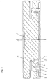
- the figures show a so-called weighing or weighing disc, ie a substantially rotationally symmetrical cylindrical load cell having a rotation axis A.
- the load cell has a height which is substantially lower compared to load cells, such as weighing beam and thus has a total of a flat disc-like outer shape, such as especially in the overall view of FIG. 1 to see.
- the weighing disk has an inner cylindrical metal core 1a with a load introduction plate 1 concentrically formed thereon and extending substantially over the entire diameter of the load cell. Furthermore, the weighing disk has a first radially extending on the metal core and axially spaced from the load introduction plate 1 thin and thus flexible upon application of force or articulated connecting web 2 via an annular deformation body 3 is connected to the load introduction plate 1. On the opposite, ie radially outer side of the deformation body 3, the annular deformation body 3 is connected to a second, equally annular, concentrically arranged thin connecting web 4 to an annular, again concentrically formed Lastaus effetsteil 5. The Lastaus effetsteil 5 extends from the connecting web 4 axially in the opposite direction to the load introduction plate 1. On the opposite, ie radially outer side of Lastaus effetsteils 5 this is connected via a third, equally annular, concentrically arranged thin connecting web 6 to an annular, in turn concentrically formed mounting flange 7.
- All of the aforementioned elements of the weighing disk are made of a piece of material.
- this is mounted on the mounting flange 7 on a support plate not shown in the figures and the load introduction plate 1 simultaneously fulfills the function of a power transmission element, which so far according to the prior art described above as a separate part of the opposite side to the carrier plate with the weighing table had to be connected.
- the load introduction plate is provided with a flat surface 1 b and expediently with a centering hole 9.
- a so-called ribbed plate can be added.
- the load introduction plate 1 may be equipped in addition to or alternatively to a center hole 9 with a number of centering openings 10 which each spaced from each other in the outer region of the load introduction plate 1 through this extend parallel to the axis A.
- the individual centering openings are expediently spaced from one another in the circumferential direction in each case.
- the embodiment shown is the load introduction plate 1 with a surface 1c in kind equipped with a spherical cap, as is often necessary, for example, in a Ofenversky.
- FIGS. 2 to 5 it is expedient to manufacture the two connecting webs 2 and 4 at approximately the same level or the same axial distance to the plane of the load introduction plate 1 and in the same axial thickness and radial length to the annular deformation body 3 between the load introduction plate 1 and the Lastaus effetsteil 5 uniformly coupled, so that each corresponding load effects on the connecting webs 2 and 4 lead to mutually corresponding forces curves and the deformation body 3 is thus coupled or articulated uniformly via the two opposite connecting webs 2 and 4.
- the deformation body 3 extends from the connecting webs 2 and 4 axially in the opposite direction to the load introduction plate 1 toward a free front end 3b.
- the third flexible connecting web 6 between the Lastaus effetsteil 5 and the mounting flange 7 in turn reduces undesirable force influences, which are caused by the necessary attachment of the load cell to the carrier plate substantially.
- the position, ie the radial middle plane, of this connecting web 6 with respect to the load discharge part 5 and the fastening flange 7 and also the axial thickness of the connecting web 6 and the axial position of the radially extending middle plane, and / or strength of the mounting flange 7 adjustable.
- FIGS. 2 to 5 different embodiments are shown.
- the strength and position of the connecting web 6 can be worked out, for example, by grooves 6a, 6b in an extremely simple manner from a region of the fastening flange adjoining the load discharge part 5 during manufacture of the weighing cell.
- the mounting flange 7, as in FIG. 1 can be seen to be equipped with a number of through holes 11 which each spaced from each other through the mounting flange 7 extend parallel to the axis A, to the mounting flange to the support plate, for example by means of screw, to be attached.
- the passage openings 11 may for this purpose also have an internal thread. The influence of such an attachment between the load cell and the carrier plate and possibly further connection construction is, as already mentioned above, minimized via the connecting web 6.
- the deformation body 3 is expediently equipped with strain gauges on the side opposite the load introduction plate 1 in such a way that both longitudinal expansions and transverse contractions are detected, in response to a deformation of the deformation body 3 indicated by V as a result of tangential forces F y acting on the load introduction plate 1 act.
- the transducers for example, on the end face 3b of the deformation body 3 are arranged such that four radially directed and circumferentially equally spaced and four tangentially directed and equal in the circumferential direction spaced-apart transducers are applied, as in the DE 10 2006 034 086 described.
- a bottom plate 8 may further be connected, for example welded, to the load discharge part 5 which, together with the load discharge part, forms a cavity for the deformation body 3 and the material core 1a.
- the bottom plate can be made thinner or thicker.
Landscapes
- Physics & Mathematics (AREA)
- General Physics & Mathematics (AREA)
- Measurement Of Force In General (AREA)
Priority Applications (1)
| Application Number | Priority Date | Filing Date | Title |
|---|---|---|---|
| PL09014330T PL2187187T3 (pl) | 2008-11-17 | 2009-11-17 | Dysk wagowy |
Applications Claiming Priority (1)
| Application Number | Priority Date | Filing Date | Title |
|---|---|---|---|
| DE102008057796A DE102008057796B4 (de) | 2008-11-17 | 2008-11-17 | Wägedisc |
Publications (3)
| Publication Number | Publication Date |
|---|---|
| EP2187187A2 true EP2187187A2 (fr) | 2010-05-19 |
| EP2187187A3 EP2187187A3 (fr) | 2011-05-18 |
| EP2187187B1 EP2187187B1 (fr) | 2017-09-13 |
Family
ID=41716448
Family Applications (1)
| Application Number | Title | Priority Date | Filing Date |
|---|---|---|---|
| EP09014330.6A Active EP2187187B1 (fr) | 2008-11-17 | 2009-11-17 | Disque de balance |
Country Status (5)
| Country | Link |
|---|---|
| EP (1) | EP2187187B1 (fr) |
| DE (1) | DE102008057796B4 (fr) |
| ES (1) | ES2643965T3 (fr) |
| PL (1) | PL2187187T3 (fr) |
| PT (1) | PT2187187T (fr) |
Cited By (1)
| Publication number | Priority date | Publication date | Assignee | Title |
|---|---|---|---|---|
| EP3971546A1 (fr) * | 2020-09-17 | 2022-03-23 | Delta Electronics, Inc. | Cellule de charge |
Families Citing this family (1)
| Publication number | Priority date | Publication date | Assignee | Title |
|---|---|---|---|---|
| DE102019107132A1 (de) * | 2019-03-20 | 2020-09-24 | Minebea Intec GmbH | Wägezelle mit Luftdruckkompensation |
Citations (2)
| Publication number | Priority date | Publication date | Assignee | Title |
|---|---|---|---|---|
| DE3937318C1 (en) | 1989-11-09 | 1991-05-23 | Carl Schenck Ag, 6100 Darmstadt, De | Force measuring unit with two concentric deformation rings - having electromechanical strain gauges on surface providing electrical values |
| DE102006034086A1 (de) | 2006-07-20 | 2008-01-31 | Schenck Process Gmbh | Kraftmessdose |
Family Cites Families (5)
| Publication number | Priority date | Publication date | Assignee | Title |
|---|---|---|---|---|
| DE2614265A1 (de) * | 1976-04-02 | 1977-10-06 | Erich Brosa | Flache kraftmessdose |
| DE3823673A1 (de) * | 1988-07-13 | 1990-01-18 | Philips Patentverwaltung | Druck- bzw. kraftaufnehmer mit einer axialsymmetrischen, druck- bzw. kraftaufnehmenden kreisplattenfeder |
| US5111702A (en) * | 1990-06-22 | 1992-05-12 | Hottinger Baldwin Measurements, Inc. | Torsion ring transducer |
| DE4104926A1 (de) * | 1991-02-18 | 1992-08-20 | Gassmann Theiss Messtech | Biegering-kraftaufnehmer |
| DE4331149A1 (de) * | 1993-09-14 | 1995-03-16 | Gassmann Theiss Messtech | Flache Waage, insbesondere Radlastwaage |
-
2008
- 2008-11-17 DE DE102008057796A patent/DE102008057796B4/de not_active Expired - Fee Related
-
2009
- 2009-11-17 PT PT90143306T patent/PT2187187T/pt unknown
- 2009-11-17 EP EP09014330.6A patent/EP2187187B1/fr active Active
- 2009-11-17 PL PL09014330T patent/PL2187187T3/pl unknown
- 2009-11-17 ES ES09014330.6T patent/ES2643965T3/es active Active
Patent Citations (2)
| Publication number | Priority date | Publication date | Assignee | Title |
|---|---|---|---|---|
| DE3937318C1 (en) | 1989-11-09 | 1991-05-23 | Carl Schenck Ag, 6100 Darmstadt, De | Force measuring unit with two concentric deformation rings - having electromechanical strain gauges on surface providing electrical values |
| DE102006034086A1 (de) | 2006-07-20 | 2008-01-31 | Schenck Process Gmbh | Kraftmessdose |
Cited By (1)
| Publication number | Priority date | Publication date | Assignee | Title |
|---|---|---|---|---|
| EP3971546A1 (fr) * | 2020-09-17 | 2022-03-23 | Delta Electronics, Inc. | Cellule de charge |
Also Published As
| Publication number | Publication date |
|---|---|
| ES2643965T3 (es) | 2017-11-27 |
| EP2187187A3 (fr) | 2011-05-18 |
| EP2187187B1 (fr) | 2017-09-13 |
| DE102008057796B4 (de) | 2012-12-13 |
| PL2187187T3 (pl) | 2018-02-28 |
| PT2187187T (pt) | 2017-12-20 |
| DE102008057796A1 (de) | 2010-05-20 |
Similar Documents
| Publication | Publication Date | Title |
|---|---|---|
| EP3507580B1 (fr) | Capteur de couple à transmission de couple élastique radialement | |
| EP3507581B1 (fr) | Capteur de couple à rayon de dérivation | |
| DE112007003595B4 (de) | Drehmomentmessflansch | |
| EP3507582B1 (fr) | Capteur de couple avec membrane d'étanchéité | |
| EP2663847B1 (fr) | Dispositif destiné à convertir une force ou une pression en un signal électrique, et procédé de production d'un tel dispositif | |
| EP0575634A1 (fr) | Palpeur de couple | |
| EP0465881B1 (fr) | Capteur de force avec anneau de torsion | |
| DE2946868A1 (de) | Druckkraftmesseinrichtung mit ringfoermigem verformungskoerper | |
| DE102012024264A1 (de) | Drehmomentsensor | |
| EP0288985B1 (fr) | Capteur de pesage de type anneau courbé | |
| EP2187187B1 (fr) | Disque de balance | |
| DE3812860A1 (de) | Ringtorsions-kraftmessvorrichtung | |
| EP1798441A1 (fr) | Ressort à diaphragme | |
| DE202004009330U1 (de) | Drucksensor für abrasive Medien | |
| WO2018024519A1 (fr) | Dispositif de mesure de force à axe simple ou à axes multiples pourvu de zone de déformation réduite | |
| DE10055933A1 (de) | Aufnehmer zum Messen von Belastungen | |
| EP2362200A1 (fr) | Douille de mesure de force ainsi que de dispositif de mesure de force | |
| DE102018113771B4 (de) | Messvorrichtung zur Ermittlung von Zug- und Druckkräften, insbesondere Wägezelle | |
| DE102016010546B3 (de) | Drehmomentsensor mit axialem Anschlagelement | |
| DE102016118045B4 (de) | Querkraft-unempfindliche Messzelle | |
| DE19826629A1 (de) | Kraftmeßvorrichtung | |
| DE102019104970A1 (de) | Wägezelle mit Querkrafterfassung | |
| DE3423696A1 (de) | Druckmessaufnehmer | |
| EP3450948B1 (fr) | Dispositif dynamométrique | |
| DD257491A1 (de) | Kapazitive, bauteilintegrierte kraftmessanordnung |
Legal Events
| Date | Code | Title | Description |
|---|---|---|---|
| PUAI | Public reference made under article 153(3) epc to a published international application that has entered the european phase |
Free format text: ORIGINAL CODE: 0009012 |
|
| AK | Designated contracting states |
Kind code of ref document: A2 Designated state(s): AT BE BG CH CY CZ DE DK EE ES FI FR GB GR HR HU IE IS IT LI LT LU LV MC MK MT NL NO PL PT RO SE SI SK SM TR |
|
| AX | Request for extension of the european patent |
Extension state: AL BA RS |
|
| PUAL | Search report despatched |
Free format text: ORIGINAL CODE: 0009013 |
|
| AK | Designated contracting states |
Kind code of ref document: A3 Designated state(s): AT BE BG CH CY CZ DE DK EE ES FI FR GB GR HR HU IE IS IT LI LT LU LV MC MK MT NL NO PL PT RO SE SI SK SM TR |
|
| AX | Request for extension of the european patent |
Extension state: AL BA RS |
|
| RIC1 | Information provided on ipc code assigned before grant |
Ipc: G01G 3/14 20060101AFI20100305BHEP Ipc: G01L 5/16 20060101ALI20110414BHEP Ipc: G01L 1/22 20060101ALI20110414BHEP |
|
| 17P | Request for examination filed |
Effective date: 20111027 |
|
| RAP1 | Party data changed (applicant data changed or rights of an application transferred) |
Owner name: SCHENCK PROCESS EUROPE GMBH |
|
| GRAP | Despatch of communication of intention to grant a patent |
Free format text: ORIGINAL CODE: EPIDOSNIGR1 |
|
| STAA | Information on the status of an ep patent application or granted ep patent |
Free format text: STATUS: GRANT OF PATENT IS INTENDED |
|
| INTG | Intention to grant announced |
Effective date: 20170411 |
|
| GRAS | Grant fee paid |
Free format text: ORIGINAL CODE: EPIDOSNIGR3 |
|
| GRAJ | Information related to disapproval of communication of intention to grant by the applicant or resumption of examination proceedings by the epo deleted |
Free format text: ORIGINAL CODE: EPIDOSDIGR1 |
|
| GRAL | Information related to payment of fee for publishing/printing deleted |
Free format text: ORIGINAL CODE: EPIDOSDIGR3 |
|
| STAA | Information on the status of an ep patent application or granted ep patent |
Free format text: STATUS: REQUEST FOR EXAMINATION WAS MADE |
|
| GRAP | Despatch of communication of intention to grant a patent |
Free format text: ORIGINAL CODE: EPIDOSNIGR1 |
|
| STAA | Information on the status of an ep patent application or granted ep patent |
Free format text: STATUS: GRANT OF PATENT IS INTENDED |
|
| INTC | Intention to grant announced (deleted) | ||
| GRAA | (expected) grant |
Free format text: ORIGINAL CODE: 0009210 |
|
| STAA | Information on the status of an ep patent application or granted ep patent |
Free format text: STATUS: THE PATENT HAS BEEN GRANTED |
|
| INTG | Intention to grant announced |
Effective date: 20170726 |
|
| AK | Designated contracting states |
Kind code of ref document: B1 Designated state(s): AT BE BG CH CY CZ DE DK EE ES FI FR GB GR HR HU IE IS IT LI LT LU LV MC MK MT NL NO PL PT RO SE SI SK SM TR |
|
| REG | Reference to a national code |
Ref country code: GB Ref legal event code: FG4D Free format text: NOT ENGLISH |
|
| REG | Reference to a national code |
Ref country code: CH Ref legal event code: EP |
|
| REG | Reference to a national code |
Ref country code: CH Ref legal event code: NV Representative=s name: FIAMMENGHI-FIAMMENGHI, CH |
|
| REG | Reference to a national code |
Ref country code: IE Ref legal event code: FG4D Free format text: LANGUAGE OF EP DOCUMENT: GERMAN |
|
| REG | Reference to a national code |
Ref country code: AT Ref legal event code: REF Ref document number: 928618 Country of ref document: AT Kind code of ref document: T Effective date: 20171015 |
|
| REG | Reference to a national code |
Ref country code: DE Ref legal event code: R096 Ref document number: 502009014357 Country of ref document: DE |
|
| REG | Reference to a national code |
Ref country code: FR Ref legal event code: PLFP Year of fee payment: 9 |
|
| REG | Reference to a national code |
Ref country code: ES Ref legal event code: FG2A Ref document number: 2643965 Country of ref document: ES Kind code of ref document: T3 Effective date: 20171127 |
|
| REG | Reference to a national code |
Ref country code: PT Ref legal event code: SC4A Ref document number: 2187187 Country of ref document: PT Date of ref document: 20171220 Kind code of ref document: T Free format text: AVAILABILITY OF NATIONAL TRANSLATION Effective date: 20171212 |
|
| REG | Reference to a national code |
Ref country code: NL Ref legal event code: FP |
|
| REG | Reference to a national code |
Ref country code: LT Ref legal event code: MG4D |
|
| PG25 | Lapsed in a contracting state [announced via postgrant information from national office to epo] |
Ref country code: LT Free format text: LAPSE BECAUSE OF FAILURE TO SUBMIT A TRANSLATION OF THE DESCRIPTION OR TO PAY THE FEE WITHIN THE PRESCRIBED TIME-LIMIT Effective date: 20170913 Ref country code: SE Free format text: LAPSE BECAUSE OF FAILURE TO SUBMIT A TRANSLATION OF THE DESCRIPTION OR TO PAY THE FEE WITHIN THE PRESCRIBED TIME-LIMIT Effective date: 20170913 Ref country code: HR Free format text: LAPSE BECAUSE OF FAILURE TO SUBMIT A TRANSLATION OF THE DESCRIPTION OR TO PAY THE FEE WITHIN THE PRESCRIBED TIME-LIMIT Effective date: 20170913 Ref country code: NO Free format text: LAPSE BECAUSE OF FAILURE TO SUBMIT A TRANSLATION OF THE DESCRIPTION OR TO PAY THE FEE WITHIN THE PRESCRIBED TIME-LIMIT Effective date: 20171213 Ref country code: FI Free format text: LAPSE BECAUSE OF FAILURE TO SUBMIT A TRANSLATION OF THE DESCRIPTION OR TO PAY THE FEE WITHIN THE PRESCRIBED TIME-LIMIT Effective date: 20170913 |
|
| PG25 | Lapsed in a contracting state [announced via postgrant information from national office to epo] |
Ref country code: LV Free format text: LAPSE BECAUSE OF FAILURE TO SUBMIT A TRANSLATION OF THE DESCRIPTION OR TO PAY THE FEE WITHIN THE PRESCRIBED TIME-LIMIT Effective date: 20170913 Ref country code: BG Free format text: LAPSE BECAUSE OF FAILURE TO SUBMIT A TRANSLATION OF THE DESCRIPTION OR TO PAY THE FEE WITHIN THE PRESCRIBED TIME-LIMIT Effective date: 20171213 Ref country code: GR Free format text: LAPSE BECAUSE OF FAILURE TO SUBMIT A TRANSLATION OF THE DESCRIPTION OR TO PAY THE FEE WITHIN THE PRESCRIBED TIME-LIMIT Effective date: 20171214 |
|
| PG25 | Lapsed in a contracting state [announced via postgrant information from national office to epo] |
Ref country code: RO Free format text: LAPSE BECAUSE OF FAILURE TO SUBMIT A TRANSLATION OF THE DESCRIPTION OR TO PAY THE FEE WITHIN THE PRESCRIBED TIME-LIMIT Effective date: 20170913 Ref country code: CZ Free format text: LAPSE BECAUSE OF FAILURE TO SUBMIT A TRANSLATION OF THE DESCRIPTION OR TO PAY THE FEE WITHIN THE PRESCRIBED TIME-LIMIT Effective date: 20170913 |
|
| PG25 | Lapsed in a contracting state [announced via postgrant information from national office to epo] |
Ref country code: SK Free format text: LAPSE BECAUSE OF FAILURE TO SUBMIT A TRANSLATION OF THE DESCRIPTION OR TO PAY THE FEE WITHIN THE PRESCRIBED TIME-LIMIT Effective date: 20170913 Ref country code: IS Free format text: LAPSE BECAUSE OF FAILURE TO SUBMIT A TRANSLATION OF THE DESCRIPTION OR TO PAY THE FEE WITHIN THE PRESCRIBED TIME-LIMIT Effective date: 20180113 Ref country code: SM Free format text: LAPSE BECAUSE OF FAILURE TO SUBMIT A TRANSLATION OF THE DESCRIPTION OR TO PAY THE FEE WITHIN THE PRESCRIBED TIME-LIMIT Effective date: 20170913 Ref country code: EE Free format text: LAPSE BECAUSE OF FAILURE TO SUBMIT A TRANSLATION OF THE DESCRIPTION OR TO PAY THE FEE WITHIN THE PRESCRIBED TIME-LIMIT Effective date: 20170913 |
|
| REG | Reference to a national code |
Ref country code: DE Ref legal event code: R097 Ref document number: 502009014357 Country of ref document: DE |
|
| PG25 | Lapsed in a contracting state [announced via postgrant information from national office to epo] |
Ref country code: MC Free format text: LAPSE BECAUSE OF FAILURE TO SUBMIT A TRANSLATION OF THE DESCRIPTION OR TO PAY THE FEE WITHIN THE PRESCRIBED TIME-LIMIT Effective date: 20170913 |
|
| PLBE | No opposition filed within time limit |
Free format text: ORIGINAL CODE: 0009261 |
|
| STAA | Information on the status of an ep patent application or granted ep patent |
Free format text: STATUS: NO OPPOSITION FILED WITHIN TIME LIMIT |
|
| PG25 | Lapsed in a contracting state [announced via postgrant information from national office to epo] |
Ref country code: DK Free format text: LAPSE BECAUSE OF FAILURE TO SUBMIT A TRANSLATION OF THE DESCRIPTION OR TO PAY THE FEE WITHIN THE PRESCRIBED TIME-LIMIT Effective date: 20170913 |
|
| 26N | No opposition filed |
Effective date: 20180614 |
|
| REG | Reference to a national code |
Ref country code: IE Ref legal event code: MM4A |
|
| PG25 | Lapsed in a contracting state [announced via postgrant information from national office to epo] |
Ref country code: MT Free format text: LAPSE BECAUSE OF FAILURE TO SUBMIT A TRANSLATION OF THE DESCRIPTION OR TO PAY THE FEE WITHIN THE PRESCRIBED TIME-LIMIT Effective date: 20170913 |
|
| PG25 | Lapsed in a contracting state [announced via postgrant information from national office to epo] |
Ref country code: IE Free format text: LAPSE BECAUSE OF NON-PAYMENT OF DUE FEES Effective date: 20171117 |
|
| PG25 | Lapsed in a contracting state [announced via postgrant information from national office to epo] |
Ref country code: SI Free format text: LAPSE BECAUSE OF FAILURE TO SUBMIT A TRANSLATION OF THE DESCRIPTION OR TO PAY THE FEE WITHIN THE PRESCRIBED TIME-LIMIT Effective date: 20170913 |
|
| REG | Reference to a national code |
Ref country code: GB Ref legal event code: 732E Free format text: REGISTERED BETWEEN 20181115 AND 20181130 |
|
| REG | Reference to a national code |
Ref country code: ES Ref legal event code: PC2A Owner name: SCHENCK PROCESS EUROPE GMBH Effective date: 20181219 |
|
| REG | Reference to a national code |
Ref country code: BE Ref legal event code: PD Owner name: SCHENCK PROCESS EUROPE GMBH; DE Free format text: DETAILS ASSIGNMENT: CHANGE OF OWNER(S), CESSION; FORMER OWNER NAME: SCHENCK PROCESS EUROPE GMBH Effective date: 20181126 |
|
| REG | Reference to a national code |
Ref country code: NL Ref legal event code: PD Owner name: SCHENCK PROCESS EUROPE GMBH; DE Free format text: DETAILS ASSIGNMENT: CHANGE OF OWNER(S), MERGE; FORMER OWNER NAME: SCHENCK PROCESS EUROPE GMBH Effective date: 20181107 |
|
| REG | Reference to a national code |
Ref country code: LU Ref legal event code: PD Owner name: SCHENCK PROCESS EUROPE GMBH; DE Free format text: FORMER OWNER: SCHENCK PROCESS EUROPE GMBH Effective date: 20181227 |
|
| REG | Reference to a national code |
Ref country code: DE Ref legal event code: R082 Ref document number: 502009014357 Country of ref document: DE Representative=s name: ELLSPERMANN, INA, DE Ref country code: DE Ref legal event code: R081 Ref document number: 502009014357 Country of ref document: DE Owner name: SCHENCK PROCESS EUROPE GMBH, DE Free format text: FORMER OWNER: SCHENCK PROCESS EUROPE GMBH, 64293 DARMSTADT, DE |
|
| REG | Reference to a national code |
Ref country code: AT Ref legal event code: PC Ref document number: 928618 Country of ref document: AT Kind code of ref document: T Owner name: SCHENCK PROCESS EUROPE GMBH, DE Effective date: 20190304 |
|
| PG25 | Lapsed in a contracting state [announced via postgrant information from national office to epo] |
Ref country code: HU Free format text: LAPSE BECAUSE OF FAILURE TO SUBMIT A TRANSLATION OF THE DESCRIPTION OR TO PAY THE FEE WITHIN THE PRESCRIBED TIME-LIMIT; INVALID AB INITIO Effective date: 20091117 |
|
| PG25 | Lapsed in a contracting state [announced via postgrant information from national office to epo] |
Ref country code: CY Free format text: LAPSE BECAUSE OF NON-PAYMENT OF DUE FEES Effective date: 20170913 |
|
| PG25 | Lapsed in a contracting state [announced via postgrant information from national office to epo] |
Ref country code: MK Free format text: LAPSE BECAUSE OF FAILURE TO SUBMIT A TRANSLATION OF THE DESCRIPTION OR TO PAY THE FEE WITHIN THE PRESCRIBED TIME-LIMIT Effective date: 20170913 |
|
| PG25 | Lapsed in a contracting state [announced via postgrant information from national office to epo] |
Ref country code: TR Free format text: LAPSE BECAUSE OF FAILURE TO SUBMIT A TRANSLATION OF THE DESCRIPTION OR TO PAY THE FEE WITHIN THE PRESCRIBED TIME-LIMIT Effective date: 20170913 |
|
| REG | Reference to a national code |
Ref country code: DE Ref legal event code: R082 Ref document number: 502009014357 Country of ref document: DE Ref country code: DE Ref legal event code: R081 Ref document number: 502009014357 Country of ref document: DE Owner name: QLAR EUROPE GMBH, DE Free format text: FORMER OWNER: SCHENCK PROCESS EUROPE GMBH, 64293 DARMSTADT, DE |
|
| REG | Reference to a national code |
Ref country code: NL Ref legal event code: HC Owner name: QLAR EUROPE GBMH; DE Free format text: DETAILS ASSIGNMENT: CHANGE OF OWNER(S), CHANGE OF OWNER(S) NAME; FORMER OWNER NAME: SCHENCK PROCESS EUROPE GMBH Effective date: 20250428 |
|
| REG | Reference to a national code |
Ref country code: LU Ref legal event code: HC Owner name: QLAR EUROPE GMBH; DE Free format text: FORMER OWNER: SCHENCK PROCESS EUROPE GMBH Effective date: 20250414 |
|
| REG | Reference to a national code |
Ref country code: AT Ref legal event code: HC Ref document number: 928618 Country of ref document: AT Kind code of ref document: T Owner name: QLAR EUROPE GMBH, DE Effective date: 20250407 |
|
| REG | Reference to a national code |
Ref country code: BE Ref legal event code: HC Owner name: QLAR EUROPE GMBH; DE Free format text: DETAILS ASSIGNMENT: CHANGE OF OWNER(S), CHANGE OF OWNER(S) NAME; FORMER OWNER NAME: SCHENCK PROCESS EUROPE GMBH Effective date: 20250422 |
|
| REG | Reference to a national code |
Ref country code: ES Ref legal event code: PC2A Owner name: QLAR EUROPE GMBH Effective date: 20251105 |
|
| REG | Reference to a national code |
Ref country code: CH Ref legal event code: U11 Free format text: ST27 STATUS EVENT CODE: U-0-0-U10-U11 (AS PROVIDED BY THE NATIONAL OFFICE) Effective date: 20251201 |
|
| PGFP | Annual fee paid to national office [announced via postgrant information from national office to epo] |
Ref country code: PT Payment date: 20251106 Year of fee payment: 17 |
|
| PGFP | Annual fee paid to national office [announced via postgrant information from national office to epo] |
Ref country code: NL Payment date: 20251119 Year of fee payment: 17 Ref country code: LU Payment date: 20251119 Year of fee payment: 17 |
|
| PGFP | Annual fee paid to national office [announced via postgrant information from national office to epo] |
Ref country code: DE Payment date: 20251119 Year of fee payment: 17 |
|
| PGFP | Annual fee paid to national office [announced via postgrant information from national office to epo] |
Ref country code: GB Payment date: 20251121 Year of fee payment: 17 |
|
| PGFP | Annual fee paid to national office [announced via postgrant information from national office to epo] |
Ref country code: AT Payment date: 20251120 Year of fee payment: 17 |
|
| PGFP | Annual fee paid to national office [announced via postgrant information from national office to epo] |
Ref country code: IT Payment date: 20251121 Year of fee payment: 17 |
|
| PGFP | Annual fee paid to national office [announced via postgrant information from national office to epo] |
Ref country code: FR Payment date: 20251121 Year of fee payment: 17 |
|
| PGFP | Annual fee paid to national office [announced via postgrant information from national office to epo] |
Ref country code: BE Payment date: 20251119 Year of fee payment: 17 |
|
| PGFP | Annual fee paid to national office [announced via postgrant information from national office to epo] |
Ref country code: CH Payment date: 20251201 Year of fee payment: 17 |
|
| PGFP | Annual fee paid to national office [announced via postgrant information from national office to epo] |
Ref country code: PL Payment date: 20251107 Year of fee payment: 17 |
|
| PGFP | Annual fee paid to national office [announced via postgrant information from national office to epo] |
Ref country code: ES Payment date: 20251229 Year of fee payment: 17 |