EP2187251A2 - Schmales katadioptrisches Objektiv mit ultrahoher NA und mit einem Manginspiegel - Google Patents
Schmales katadioptrisches Objektiv mit ultrahoher NA und mit einem Manginspiegel Download PDFInfo
- Publication number
- EP2187251A2 EP2187251A2 EP10000348A EP10000348A EP2187251A2 EP 2187251 A2 EP2187251 A2 EP 2187251A2 EP 10000348 A EP10000348 A EP 10000348A EP 10000348 A EP10000348 A EP 10000348A EP 2187251 A2 EP2187251 A2 EP 2187251A2
- Authority
- EP
- European Patent Office
- Prior art keywords
- objective
- light energy
- aspheric
- lens
- catadioptric
- Prior art date
- Legal status (The legal status is an assumption and is not a legal conclusion. Google has not performed a legal analysis and makes no representation as to the accuracy of the status listed.)
- Granted
Links
- 238000003384 imaging method Methods 0.000 claims abstract description 33
- VYPSYNLAJGMNEJ-UHFFFAOYSA-N Silicium dioxide Chemical compound O=[Si]=O VYPSYNLAJGMNEJ-UHFFFAOYSA-N 0.000 claims description 86
- 239000005350 fused silica glass Substances 0.000 claims description 86
- 239000000463 material Substances 0.000 claims description 31
- 239000011521 glass Substances 0.000 claims description 25
- 230000004075 alteration Effects 0.000 claims description 17
- 238000000034 method Methods 0.000 claims description 7
- WUKWITHWXAAZEY-UHFFFAOYSA-L calcium difluoride Chemical compound [F-].[F-].[Ca+2] WUKWITHWXAAZEY-UHFFFAOYSA-L 0.000 claims description 3
- 229910001634 calcium fluoride Inorganic materials 0.000 claims description 3
- 230000005499 meniscus Effects 0.000 claims description 3
- 238000013461 design Methods 0.000 description 125
- 230000003287 optical effect Effects 0.000 description 35
- 230000035945 sensitivity Effects 0.000 description 22
- 238000005457 optimization Methods 0.000 description 18
- 238000005286 illumination Methods 0.000 description 17
- 230000009286 beneficial effect Effects 0.000 description 12
- 238000004519 manufacturing process Methods 0.000 description 11
- 230000008901 benefit Effects 0.000 description 9
- 238000007689 inspection Methods 0.000 description 9
- 238000013459 approach Methods 0.000 description 7
- 230000009467 reduction Effects 0.000 description 7
- 238000012937 correction Methods 0.000 description 6
- 230000006872 improvement Effects 0.000 description 6
- 206010010071 Coma Diseases 0.000 description 5
- 238000000386 microscopy Methods 0.000 description 4
- 239000004065 semiconductor Substances 0.000 description 4
- 230000005540 biological transmission Effects 0.000 description 3
- 230000015556 catabolic process Effects 0.000 description 3
- 238000006731 degradation reaction Methods 0.000 description 3
- 230000003595 spectral effect Effects 0.000 description 3
- 235000012431 wafers Nutrition 0.000 description 3
- 150000001875 compounds Chemical class 0.000 description 2
- 230000007547 defect Effects 0.000 description 2
- 230000001747 exhibiting effect Effects 0.000 description 2
- 238000001459 lithography Methods 0.000 description 2
- 239000004593 Epoxy Substances 0.000 description 1
- 238000010521 absorption reaction Methods 0.000 description 1
- 230000006978 adaptation Effects 0.000 description 1
- 238000001514 detection method Methods 0.000 description 1
- 238000001914 filtration Methods 0.000 description 1
- 239000012530 fluid Substances 0.000 description 1
- 239000005383 fluoride glass Substances 0.000 description 1
- 238000012986 modification Methods 0.000 description 1
- 230000004048 modification Effects 0.000 description 1
- 238000012634 optical imaging Methods 0.000 description 1
- 239000002245 particle Substances 0.000 description 1
- 230000010287 polarization Effects 0.000 description 1
- 238000012545 processing Methods 0.000 description 1
- 238000011160 research Methods 0.000 description 1
- 238000012360 testing method Methods 0.000 description 1
- 238000002211 ultraviolet spectrum Methods 0.000 description 1
Images


Classifications
-
- G—PHYSICS
- G02—OPTICS
- G02B—OPTICAL ELEMENTS, SYSTEMS OR APPARATUS
- G02B17/00—Systems with reflecting surfaces, with or without refracting elements
- G02B17/08—Catadioptric systems
- G02B17/0856—Catadioptric systems comprising a refractive element with a reflective surface, the reflection taking place inside the element, e.g. Mangin mirrors
-
- G—PHYSICS
- G02—OPTICS
- G02B—OPTICAL ELEMENTS, SYSTEMS OR APPARATUS
- G02B17/00—Systems with reflecting surfaces, with or without refracting elements
- G02B17/008—Systems specially adapted to form image relays or chained systems
-
- G—PHYSICS
- G02—OPTICS
- G02B—OPTICAL ELEMENTS, SYSTEMS OR APPARATUS
- G02B17/00—Systems with reflecting surfaces, with or without refracting elements
- G02B17/08—Catadioptric systems
- G02B17/0892—Catadioptric systems specially adapted for the UV
-
- G—PHYSICS
- G02—OPTICS
- G02B—OPTICAL ELEMENTS, SYSTEMS OR APPARATUS
- G02B21/00—Microscopes
- G02B21/02—Objectives
- G02B21/04—Objectives involving mirrors
Definitions
- the present invention relates generally to the field of optical imaging and more particularly to catadioptric optical systems used for microscopic imaging, inspection, and lithography applications.
- Microscopes have been used in various imaging situations, including biology, metrology, semiconductor inspection, and other complex inspection applications where high resolution images of small areas and/or features are desired.
- the objective disclosed in the '374 application is a small catadioptric objective exhibiting beneficial optical qualities.
- the small size catadioptric optical design of the '374 application exhibits generally good overall performance, especially at relatively high numerical apertures (NAs) over a very broad spectral range in the deep ultra-violet (DUV) light region.
- NAs numerical apertures
- DUV deep ultra-violet
- the objectives disclosed in the '517 patent are large catadioptric objectives that also exhibit desired optical qualities.
- the large catadioptric optical designs in the '517 patent are corrected over a narrow spectral bandwidth and are capable of ultra-high NAs imaging over very large field sizes.
- Such objectives generally provide advantages in their size, arrangement of lens groups, and the fact that they can be made from a single glass material.
- Such designs include lenses that can generally be categorized into three groups; a focusing lens group, a field lens group, and a catadioptric group. Lenses in these groups have very different arrangements and are used in different ways to achieve different goals.
- the NA represents the range of angles for which light can be delivered to and collected from a specimen using the design.
- the field size is the diameter at the specimen location over which all the optical performance requirements are satisfied.
- certain systems may successfully and efficiently employ "ultra-high NA" imaging over large field sizes.
- ultra-high NA illumination and imaging angles may include but are not limited to angles up to and above 76 degrees.
- Certain previous designs can only provide NAs lower than this ultra-high range, and exhibit smaller field size, larger optical element diameters, or very tight tolerances in the high end applications discussed.
- NAs In general, larger NAs, larger field sizes, small element diameters, and loose tolerances for a given objective can be beneficial, particularly when constructed from a single material and/ or operating in association with light energy at specific advantageous wavelengths.
- optical element diameters With respect to optical element diameters, smaller diameters result in more compact and less expensive to manufacture objectives. Further, smaller optical element diameters can be employed in certain specific applications, such as microscopy.
- an ultra-high NA and large field can offer improved capabilities when inspecting specimens using light energy in the DUV range. For example, but not by way of limitation, operation at wavelengths of 193, 213, 244, 257, 266, 325, 355 or greater up through visible wavelengths may result in beneficial performance in certain circumstances. In addition, small size and loose manufacturing tolerances make the design practical to manufacture. Previous ultra-high NA designs do not demonstrate this capability.
- an objective and method employed for use in imaging a specimen comprises: a lens group having at least one focusing lens configured to receive light energy and convert said light energy into an intermediate focused light energy; a catadioptric arrangement in which one first aspheric surface is formed and comprising a mirror element and at least one Mangin element, the arrangement being configured to receive said intermediate focused light energy from the lens group and convert said intermediate focused light energy into a controlled light energy.
- said catadioptric arrangement additionally comprises at least one lens element placed between the mirror element and the at least one Mangin element.
- a small catadioptric objective having ultra-high numerical aperture, large field, small size, and loose tolerances for use in advanced applications such as microscopy and semiconductor inspection.
- This small ultra-high NA objective is ideally suited for a variety of dark field and bright field imaging schemes.
- the present design is capable of delivering and collecting light at angles up to 76 degrees from the sample normal.
- the present design may be used and optimized for light beams having different wavelengths, from the infrared to the deep ultraviolet.
- fluoride glasses may be employed due to their transmission properties.
- NA numerical apertures
- the present design may comprise lenses formed from a single glass material.
- fused silica is employed due to its high transmission properties.
- fused silica also has adequate thermal stability and is relatively easy to polish.
- the present invention uses aspheric surfaces in the catadioptric group to provide benefits over previous catadioptric designs.
- aspheric lenses comprise a compound curve rather than sections of a sphere.
- a spherical surface of a lens may be slightly altered to form a compound curve, with the result being reduced spherical aberration.
- An aspheric lens generally allows wide angle viewing with relatively low distortion.
- Previous small broad band designs typically have limited NA and field size since the net refractive power in the catadioptric group must be negative to correct for primary axial color in the focusing lens group.
- the present design uses narrow band light to obviate the requirement for axial color compensation.
- the field lens group images light energy from the catadioptric group into the focusing lens group to correct for lateral color.
- the field lens group is designed to instead be used to control monochromatic aberrations, such as high-order spherical aberration and coma.
- Previous large catadioptric ultra-high NA designs have decenter tolerances that are very tight, or restrictive, making manufacturing difficult. Tight tolerances are generally caused by steep angles of incidence in the focusing lens group. Previous designs required high angles of incidence to generate high-order spherical aberration and coma to compensate for aberrations generated inside the catadioptric group. In the present design, decenter tolerances may be reduced in the focusing lens group by reducing high-order aberrations in the catadioptric group so they do not need to be addressed by the focusing group. Reducing high-order aberrations in the catadioptric group is not a simple matter for an ultra-high NA system.
- the present design addresses higher-order spherical aberration or higher order coma by using different design approaches that incorporate aspheric surfaces in the catadioptric group.
- One design approach uses a three element catadioptric group with a spherical mirror, a lens used in triple-pass, and a Mangin element near the specimen or wafer.
- Fig. 1 illustrates one embodiment according to the present design.
- the design comprises a focusing lens group 101 and a catadioptric group 103.
- the focusing lens group 101 includes lenses 104-108.
- Intermediate image 114 is formed by first lens group 101. This design does not provide a lens in proximity to the intermediate image 114.
- the intermediate image 114 is formed in proximity to the vertex of the spherical mirror 109 in catadioptric group 103.
- the catadioptric group comprises two elements including a spherical mirror 109 and a Mangin element 110. In this design, both sides of the Mangin element 110 are aspheric.
- Table 1 presents the lens prescriptions for the embodiment illustrated in Fig. 1 .
- Table 1. Lens prescription for the design form in Fig. 1 Surf Radius Thickness Glass Diameter OBJ Infinity Infinity 0.000 STO Infinity 4.997 15.520 2 -14.000 11.579 Fused silica 16.399 3 -17.304 0.200 23.240 4 -98.007 4.000 Fused silica 24.146 5 -33.349 0.200 24.707 6 38.703 6.500 Fused silica 24.531 7 -47.501 0.200 23.797 8 61.192 4.500 Fused silica 21.950 9 -87.147 0.200 20.278 10 31.292 3.881 Fused silica 17.973 11 108.432 13.829 15.373 12 Infinity 22.122 10.244 13 175.205 20.275 Fused silica 68.000 14 1161.004 -20.275 MIRROR 56.000 15 175.205 -22.122 68.000 16 52.141 22.122 MIRROR 74.000 17
- the numbers in the leftmost column of Table 1 represent the surface number counting surfaces from the left of Fig. 1 .
- the left surface of lens 104 in the orientation presented in Fig. 1 (surface 2 in Table 1) has a radius of curvature of -14.000 mm, a thickness of 11.579 mm, and the rightmost surface (surface 2) has a radius of curvature of -17.304 mm, and is 0.2 mm from the next surface.
- the material used is fused silica.
- the first expression represents the sag of a standard spherical surface where c is the surface curvature or the inverse of the radius of curvature.
- the parameter r can range from 0 to one half of the element diameter.
- the parameter k is the conic constant. For spherical surfaces, k is equal to 0.
- the aspheric terms are included in the summation of Equation (1).
- N is the number of aspheric terms
- p is the normalized element radius (half of the element diameter)
- ⁇ represents the aspheric coefficients.
- Table 2 lists the surface sag parameters for the surfaces of the mangin mirror 103.
- Side 111 of element 110 is listed in Table 1 as surface(s) 13, 15, and 17.
- the side of an element has one surface entry in the table for each time light interacts with the element, and light contacts side 111 of element 110 three times.
- Side 112 is represented in Table 1 as surface 14 and 18.
- the numerical aperture may approach or even exceed approximately 0.97 in air.
- the focusing lens group 101 has the ability to receive light energy and transmit focused light energy.
- the catadioptric group or Mangin mirror arrangement 103 receives the intermediate energy and provides controlled light energy to the specimen 113.
- the reflected path originates at the specimen, and light reflected from the specimen is received by the catadioptric group or Mangin mirror arrangement 103 and forms and transmits reflected light energy.
- the focusing lens group receives resultant light energy and transmits focused resultant light energy.
- An aperture or mask can be placed at the aperture stop 115 to limit or modify the NA of the objective.
- fused silica uses a single glass material, fused silica.
- Other materials may be employed, but it is noted that fused silica or any material used within the design may require low absorption over the range of wavelengths supported by the objective design.
- Fused silica offers relatively high transmission properties for light energy from 190 nm through the infrared wavelengths. Because of the single material design of the ultra-high NA objective, fused silica can enable the design to be re-optimized for any center wavelength in this wavelength range. For example, the design can be optimized for use with lasers at 193, 198.5, 213, 244, 248, 257, 266, 308, 325, 351, 355, or 364 nm.
- Fig. 1 operates at a 266 nm wavelength and has a field size of approximately 3.0 mm using a maximum element diameter of 74 mm.
- This field size is significantly larger and performance significantly better than many objective designs previously employed in this wavelength range.
- This ultra-high NA objective supports a numerical aperture of approximately 0.97 in air and a polychromatic wavefront error of less than approximately 0.054 waves, levels which had been previously unachievable in combination in a single design.
- Field size in this arrangement represents the size of the area on the specimen that can be imaged the system with minimum degradation in optical performance.
- the catadioptric arrangement 103 using aspheric surfaces 109 and 111 allows the objective to simultaneously achieve the above performance goals with very loose tolerances.
- the highest sensitivity to a 10 micron element decenter in the focusing group 101 is 0.16 waves at 266 nm without compensation.
- the highest sensitivity to a 10 micron element decenter for the catadioptric group 103 is 0.3 waves at 266 nm without compensation.
- the large field size, loose tolerances, low wavefront error, and low number of elements are possible due at least in part to the use of aspheric surfaces in the catadioptric group.
- Aspheric surfaces reduce the high order field aberrations that were previously produced by spherical surfaces. In particular, high order coma is greatly reduced.
- Fig. 1 The design of Fig. 1 is self corrected, where self corrected in this context means that the objective does not require any additional optical components to correct aberrations in order to achieve inspection design specifications. In other words, no additional components are needed to provide a generally aberration free image, or the objective provides substantially complete images without need for additional compensation.
- the ability to self correct can provide for simpler optical testing metrology and optical alignment to other self corrected imaging optics. Further correction of residual aberrations using additional imaging optics is also possible, where further correction can increase the optical specifications, including but not limited to bandwidth or field size.
- Element 110 of Fig. 1 can be challenging to manufacture because both sides of the element have aspheric surfaces that must be precisely aligned.
- One method to ease this manufacturing is to make the aspheric surfaces individually on separate plates, where each plate has a thickness and the total thickness of both plates is equal to the thickness of element 110. These plates can then be aligned and optically contacted. Alternately, the two plates so formed may be attached using a UV epoxy or index matching fluid. Another option would be to design an air gap between the plates so they do not need to be attached in any manner.
- the ultra-high NA objective design presented herein can support various modes of illumination and imaging. Modes supported can include bright field and a variety of dark field illumination and imaging modes. Other modes such as confocal, differential interference contrast, polarization contrast may also be supported using the present design.
- Bright field mode is commonly used in microscope systems.
- the advantage of bright field illumination is the clarity of the image produced.
- Using bright field illumination with an objective such as that presented herein provides a relatively accurate representation of object feature size multiplied by the magnification of the optical system.
- the objective and optical components presented herein can be readily used with image comparison and processing algorithms for computerized object detection and classification.
- Bright field mode typically uses a broad band incoherent light source, but is it also possible to use laser illumination sources and to employ the objective design presented herein.
- the confocal mode has been used for optical sectioning to resolve height differences of object features. Most imaging modes have difficulty detecting changes in the height of features.
- the confocal mode forms separate images of object features at each height of interest, Comparison of the images then shows the relative heights of different features. Confocal mode may be employed using the design presented herein.
- Dark field mode has been used to detect features on objects.
- the advantage of the dark field mode is that flat specular areas scatter very little light toward the detector, resulting in a dark image. Surface features or objects protruding above the object tend to scatter light toward the detector.
- dark field imaging produces an image of features, particles, or other irregularities on a dark background.
- the present design may be employed with dark field mode illumination. Dark field mode provides a large resultant signal upon striking small features that scatter light. This large resultant signal allows larger pixels to be employed for a given feature size, permitting faster object inspections. Fourier filtering can also be used to minimize the repeating pattern signal and enhance the defect signal to noise ratio during dark field inspection.
- dark field modes each including a specific illumination and collection scheme. Illumination and collection schemes can be chosen such that the scattered and diffracted light collected from the object provides an acceptable signal-to- noise ratio.
- Certain optical systems use different dark field imaging modes including ring dark field, laser directional dark field, double dark field, and central dark ground. Each of these dark field imaging modes may be employed in the present design.
- a second embodiment according to the present design with seven separate elements is possible.
- the form of the objective is similar to that presented in Fig. 1 .
- the major difference between this lens prescription and the lens prescription in Table 1 and Table 2 is the optimization for a smaller 2 mm field size. This optimization enables a reduction in the diameter of the elements and length of the objective as well as an improvement in the optical performance.
- Table 3 presents the lens prescriptions for the second embodiment with similar form to that presented in Fig 1 .
- Table 3 Lens prescription for the second embodiment with the form presented in Fig. 1.
- the left surface of lens 104 in the orientation presented in Fig. 1 (surface 2 in Table 3) has a radius of curvature of -9.324 mm, a thickness of 7.711 mm, and the rightmost surface (surface 3) has a radius of curvature of -11.524, and is 0.133 from the next surface.
- the material used is fused silica.
- the surfaces corresponding to side 111 and 112 of element 110 are aspheric.
- the aspheric surface sag for this design is described using Equation (1).
- the aspheric surface sag parameters for the lens prescription in Table 3 are listed in Table 4.
- the lens prescription of Table 3 and Table 4 operates at a 266 nm wavelength and has a field size of approximately 2.0 mm.
- the maximum element diameter is 49 mm which is significantly smaller than many objective designs previously employed with this field size and performance.
- the small size of this objective is particularly beneficial in view of the performance characteristics of the objective.
- This ultra-high NA objective supports a numerical aperture of approximately 0.97 in air and a polychromatic wavefront error of less than approximately 0.0358 waves, levels previously unachievable in combination in a single design.
- the catadioptric lens prescription listed in Table 3 and Table 4 using aspheric surfaces allows the objective to simultaneously achieve the above performance goals with very loose tolerances, i.e. certain slight imperfections in manufacturing to not critically inhibit performance.
- the highest sensitivity to a 10 micron element decenter in the focusing group 101 is 0.15 waves at 266 nm without compensation.
- the highest sensitivity to a 10 micron element decenter for the catadioptric group 103 is 0.29 waves at 266 nm without compensation.
- the large field size, loose tolerances, low wavefront error, and low number of elements are possible due the use of aspheric surfaces in the catadioptric group.
- the lens prescription presented in Table 3 and Table 4 thus uses a single glass material, fused silica. Other materials may be employed in a similar fashion to the design presented in Fig. 1 . Re-optimization for other wavelengths requires slight tuning or altering of components, generally within the abilities of those skilled in the art.
- the lens prescription presented in Table 3 and Table 4 is self corrected in a similar fashion to that presented in Table 1 and Table 2. Also, the ultra-high NA objective design presented herein can support various modes of illumination and imaging as the objective in Fig. 1 .
- a third embodiment according to the present design with seven separate elements is possible.
- the form of the objective is similar to that presented in Fig. 1 .
- the major difference between this lens prescription and the lens prescription in Table 1 and Table 2 is optimization for a smaller 1 mm field size. This 1 mm field size enables a reduction in the diameter of the elements and length of the objective as well as an improvement in the optical performance.
- Table 5 presents the lens prescriptions for this second embodiment having similar form to the design presented in Fig. 1 .
- Table 5 presents the lens prescriptions for this second embodiment having similar form to the design presented in Fig. 1 .
- Table 5 presents the lens prescriptions for this second embodiment having similar form to the design presented in Fig. 1 .
- Table 5 presents the lens prescriptions for this second embodiment having similar form to the design presented in Fig. 1 .
- Table 5 presents the lens prescriptions for this second embodiment having similar form to the design presented in Fig. 1 .
- Table 5 presents the lens prescriptions for this second embodiment having similar form to the design presented in
- the surfaces corresponding to side 111 and 112 of element 110 are aspheric.
- the aspheric surface sag for this design is described using Equation (1).
- the aspheric surface sag parameters for the lens prescription in Table 5 are listed in Table 6.
- the lens prescription of Table 5 and Table 6 operates at a 266nm wavelength and has a field size of approximately 1.0 mm.
- the maximum element diameter is 25mm, significantly smaller than many objective designs previously employed with this field size and performance.
- the small size of this objective is particularly beneficial in view of the performance characteristics of the objective.
- This ultra-high NA objective supports a numerical aperture of approximately 0.97 in air and a polychromatic wavefront error of less than approximately 0.0263 waves, previously unachievable in combination in a single design.
- field size represents the size of the area on the specimen that can be imaged the system with minimum degradation in optical performance.
- the catadioptric lens prescription listed in Table 5 and Table 6 using aspheric surfaces allows the objective to simultaneously achieve the above performance goals with very loose tolerances.
- the highest sensitivity to a 10 micron element decenter in the focusing group 101 is 0.16 waves at 266 nm without compensation.
- the highest sensitivity to a 10 micron element decenter for the catadioptric group 103 is 0.27 waves at 266 nm without compensation.
- the large field size, loose tolerances, low wavefront error, and low number of elements are possible due the use of aspheric surfaces in the catadioptric group.
- the lens prescription presented in Table 5 and Table 6 thus uses a single glass material, fused silica. Other materials may be employed in a similar fashion to the design presented in Fig. 1 . Re-optimization for other wavelengths requires slight tuning or altering of components, and may generally be within the abilities of those skilled in the art.
- the lens prescription presented in Table 5 and Table 6 is self corrected in a similar fashion to that presented in Table 1 and Table 2. Also, the ultrahigh NA objective design presented herein can support various modes of illumination and imaging as the objective in Fig. 1 .
- a fourth embodiment according to the present design with seven separate elements is possible.
- the form of the objective is again similar to that presented in Fig. 1 .
- the first major difference between this lens prescription and the lens prescription in Table 1 and Table 2 is the optimization for a smaller 2 mm field size. Such optimization enables the reduction in the diameter of the elements and length of the objective as well as an improvement in the optical performance.
- side 112 of element 110 is spherical while the surface of mirror element 109 aspheric. This spherical side/aspheric mirror combination can simplify the alignment of the two aspheric surfaces because they are on physically separate elements.
- Table 7 presents the lens prescriptions for the second embodiment with similar form to that presented in Fig. 1 . Table 7.
- the lens prescription of Table 7 and Table 8 operates at a 266 nm wavelength and has a field size of approximately 2.0 mm.
- the maximum element diameter is 46 mm, again significantly smaller than many objective designs previously employed with this field size and level of performance.
- the small size of this objective is particularly beneficial in view of the performance characteristics of the objective.
- This ultra-high NA objective supports a numerical aperture of approximately 0.97 in air and a polychromatic wavefront error of less than approximately 0.0358 waves, previously unachievable in combination in a single design.
- the catadioptric lens prescription listed in Table 7 and Table 8 using aspheric surfaces allows the objective to simultaneously achieve the above performance goals with very loose tolerances.
- the highest sensitivity to a 10 micron element decenter in the focusing group 101 is 0.16 waves at 266 nm without compensation.
- the highest sensitivity to a 10 micron element decenter for the catadioptric group 103 is 0.41 waves at 266 nm without compensation.
- the large field size, loose tolerances, low wavefront error, and low number of elements are possible due the use of aspheric surfaces in the catadioptric group.
- the lens prescription presented in Table 7 and Table 8 thus uses a single glass material, fused silica. Other materials may be employed in a similar fashion to the design presented in Fig. 1 . Re-optimization for other wavelengths requires slight tuning or altering of components, and may generally be within the abilities of those skilled in the art.
- the lens prescription presented in Table 7 and Table 8 is self corrected in a similar fashion to that presented in Table 1 and Table 2. Also, the ultrahigh NA objective design presented herein can support various modes of illumination and imaging as the objective in Fig. 1 .
- a fifth embodiment according to the present design with seven separate elements is possible.
- the form of the objective is very similar to that presented in Fig. 1 .
- the major difference between this lens prescription and the lens prescription in Table 1 and Table 2 is the use of aspheric surfaces to improve the performance and reduce assembly tolerances.
- the side 111 and 112 of element 110 are aspheric and the surface of mirror element 109 is aspheric.
- Table 9 presents the lens prescriptions for the second embodiment with similar form to that presented in Fig. 1 .
- the surfaces corresponding to side 111 and 112 of element 110 are aspheric.
- the surface of mirror element 109 is aspheric.
- the aspheric surface sags for this design are described using Equation (1).
- the aspheric surface sag parameters for the lens prescription in Table 9 are listed in Table 10.
- the lens prescription of Table 9 and Table 10 operates at a 266 nm wavelength and has a field size of approximately 3.0 mm.
- the maximum element diameter is 74 mm which is significantly smaller than many objective designs previously employed with this field size and performance.
- the small size of this objective is particularly beneficial in view of the performance characteristics of the objective.
- This ultra-high NA objective supports a numerical aperture of approximately 0.97 in air and a polychromatic wavefront error of less than approximately 0.0407 waves, levels which had been previously unachievable in combination in a single design.
- Field size in this arrangement represents the size of the area on the specimen that can be imaged the system with minimum degradation in optical performance.
- the catadioptric lens prescription listed in Table 9 and Table 10 using aspheric surfaces allows the objective to simultaneously achieve the above performance goals and be constructed using very loose tolerances.
- the highest sensitivity to a 10 micron element decenter in the focusing group 101 is 0.15 waves at 266 nm without compensation.
- the highest sensitivity to a 10 micron element decenter for the catadioptric group 103 is 0.28 waves at 266 nm without compensation.
- the large field size, loose tolerances, low wavefront error, and low number of elements are possible due the use of aspheric surfaces in the catadioptric group.
- the lens prescription presented in Table 9 and Table 10 thus uses a single glass material, fused silica. Other materials may be employed in a similar fashion to the design presented in Fig. 1 . Re-optimization for other wavelengths requires slight tuning or altering of components, and may generally be within the abilities of those skilled in the art.
- the lens prescription presented in Table 9 and Table 10 is self corrected in a similar fashion to that presented in Table 1 and Table 2. Also, the ultrahigh NA objective design presented herein can support various modes of illumination and imaging as the objective in Fig. 1 .
- Fig. 2 illustrates a sixth embodiment according to the present design.
- the design comprises a focusing lens group 201 a field lens group 202 and a catadioptric group 203.
- the focusing lens group 201 includes lenses 204-206.
- Intermediate image 213 is formed by first lens group 201.
- This design includes a field lens 207 in proximity to the intermediate image 213.
- the intermediate image 213 is formed in proximity to the vertex of the spherical mirror 208 in catadioptric group 203.
- the catadioptric group comprises two elements including a spherical mirror 208 and a mangin element 209. In this design, sides 210 and 211 of the Mangin element 209 are aspheric.
- the major difference between this lens prescription and the lens prescription in Table 1 and Table 2 is the optimization for a wavelength of 355 nm and a smaller 2.5 mm field size. This enables the reduction in the diameter of the elements and length of the objective as well as an improvement in the optical performance. It is also possible to reduce the number of optical elements from seven to six.
- Table 11 presents the lens prescriptions for the sixth embodiment presented in Fig. 2 .
- Table 11 Lens prescription for the sixth embodiment presented in Fig. 2.
- the surfaces corresponding to side 210 and 211 of element 209 are aspheric.
- the aspheric surface sag for this design can be described using Equation (1), where the aspheric surface sag parameters for the lens prescription in Table 11 are listed in Table 12.
- the numerical aperture may approach or even exceed approximately 0.97 in air.
- the focusing lens group 201 has the ability to receive light energy and transmit focused light energy.
- Field lens group 202 has the ability to receive intermediate light energy and transmit intermediate light energy.
- the catadioptric group or Mangin mirror arrangement 203 receives the intermediate energy and provides controlled light energy to the specimen 212. Alternately, the reflected path originates at the specimen, and light reflected from the specimen is received by the catadioptric group or Mangin mirror arrangement 203 and forms and transmits reflected light energy 213.
- the field lens group 202 receives intermediate light energy and retransmits intermediate light energy.
- the focusing lens group receives resultant light energy and transmits focused resultant light energy.
- An aperture or mask can be placed at the aperture stop 214 to limit or modify the NA of the objective.
- the lens prescription of Tables 11 and 12 operates at a 355 nm wavelength and has a field size of approximately 2.5 mm.
- the maximum element diameter is 75 mm, again significantly smaller than many objective designs previously employed with this field size and performance.
- the small size of this objective is particularly beneficial in view of the performance characteristics of the objective.
- This ultra-high NA objective supports a numerical aperture of approximately 0.97 in air and a polychromatic wavefront error of less than approximately 0.0438 waves, again a high previously unachieved performance level for a single objective design.
- the catadioptric lens prescription listed in Tables 11 and 12 using aspheric surfaces allows the objective to simultaneously achieve the above performance goals with very loose tolerances.
- the highest sensitivity to a 10 micron element decenter in the focusing group 201 is 0.13 waves at 355 nm without compensation.
- the highest sensitivity to a 10 micron element decenter in the field lens group 202 is approximately 0.18 waves at 355 nm without compensation.
- the highest sensitivity to a 10 micron element decenter for the catadioptric group 203 is 0.18 waves at 355 nm without compensation.
- the lens prescription presented in Tables 11 and 12 thus uses a single glass material, fused silica. Other materials may be employed in a similar fashion to the design presented in Fig. 1 . Re-optimization for other wavelengths requires slight tuning or altering of components, and may generally be within the abilities of those skilled in the art.
- the lens prescription presented in Tables 11 and 12 is self corrected in a similar fashion to that presented in Tables 1 and 2. Also, the ultra-high NA objective design presented herein can support various modes of illumination and imaging as the objective in Fig. 1 .
- Fig. 3 illustrates a seventh embodiment according to the present design.
- the design of Fig. 3 comprises a focusing lens group 301, a field lens group 302, and a catadioptric group 303.
- the focusing lens group 301 includes lenses 304-307.
- Intermediate image 314 is formed by first lens group 301.
- This design includes a field lens 308 in proximity to the intermediate image 314.
- the intermediate image 314 is formed in proximity to the vertex of the spherical mirror 309 in catadioptric group 303.
- the catadioptric group comprises two elements including a spherical mirror 309 and a Mangin element 310. In this design, side 311 of the Mangin element 310 is aspheric.
- This lens prescription enables the reduction in the diameter of the elements and length of the objective as well as an improvement in the optical performance.
- Using an element with a single aspheric surface on one side and a flat surface on the other can simplify manufacturing of the aspheric element.
- Table 13 presents the lens prescriptions for the embodiment presented in Fig. 3 .
- Table 13 Lens prescription for the seventh embodiment presented in Fig. 3.
- the surface corresponding to side 311 of element 209 is aspheric.
- the aspheric surface sag for this design is again described using Equation (1).
- the aspheric surface sag parameters for the lens prescription in Table 13 are listed in Table 14.
- Table 14 Aspheric surface sag parameters for the lens prescription in Table 13.
- the numerical aperture may approach or even exceed approximately 0.97 in air.
- the focusing lens group 301 has the ability to receive light energy and transmit focused light energy.
- Field lens group 302 has the ability to receive intermediate light energy and transmit intermediate light energy.
- the catadioptric group or Mangin mirror arrangement 303 receives the intermediate energy and provides controlled light energy to the specimen 314. Alternately, the reflected path originates at the specimen, and light reflected from the specimen is received by the catadioptric group or Mangin mirror arrangement 303 and forms and transmits reflected light energy 314.
- the field lens group 302 receives intermediate light energy and retransmits intermediate light energy.
- the focusing lens group receives resultant light energy and transmits focused resultant light energy.
- An aperture or mask can be placed at the aperture stop 315 to limit or modify the NA of the objective.
- the lens prescription of Tables 13 and 14 operates at a 266 nm wavelength and has a field size of approximately 1.0 mm.
- the maximum element diameter is 32 mm which is significantly smaller than many objective designs previously employed with this field size and performance.
- This ultra-high NA objective supports a numerical aperture of approximately 0.97 in air and a polychromatic wavefront error of less than approximately 0.05 waves, levels which had been previously unachievable in combination in a single design.
- the catadioptric lens prescription listed in Tables 13 and 14 using one aspheric surface allows the objective to simultaneously achieve the above performance goals with loose tolerances.
- the highest sensitivity to a 10 micron element decenter in the focusing group 301 is 0.4 waves at 266 nm without compensation.
- the highest sensitivity to a 10 micron element decenter in the field lens group 302 is 0.3 waves at 266 nm without compensation.
- the highest sensitivity to a 10 micron element decenter for the catadioptric group 303 is 0.28 waves at 266 nm without compensation.
- the large field size, loose tolerances, low wavefront error, and low number of elements are possible due the use of one aspheric surface in the catadioptric group.
- the lens prescription presented in Tables 13 and 14 thus uses a single glass material, fused silica. Other materials may be employed in a similar fashion to the design presented in Fig. 1 . Re-optimization for other wavelengths requires slight tuning or altering of components, and may generally be within the abilities of those skilled in the art.
- the lens prescription presented in Tables 13 and 14 is self corrected in a similar fashion to that presented in Tables 1 and 2. Also, the ultra-high NA objective design presented herein can support various modes of illumination and imaging as the objective in Fig. 1 .
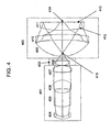
- Fig. 4 illustrates an eighth embodiment according to the present design that uses eight separate elements.
- the design comprises a focusing lens group 401, a field lens group 402, and a catadioptric group 403.
- the focusing lens group 401 includes lenses 404-407.
- Intermediate image 415 is formed by first lens group 401.
- the design further includes field lens 408 between the focusing lens group 401 and the intermediate image 415.
- the intermediate image 415 is formed in proximity to the vertex of the spherical mirror 409 in catadioptric group 403.
- the catadioptric group comprises three elements including a spherical mirror 409, lens element 410 used in triple pass, and a Mangin element 411.
- the three element arrangement for the catadioptric group 403 places the lens 410 between the spherical mirror 409 and the Mangin element 411.
- This lens 410 is shaped as a meniscus element toward the spherical mirror 409.
- the side 412 of Mangin element 411 is aspheric while side 413 remains spherical or flat.
- the surface corresponding to side 412 of element 411 is aspheric.
- the aspheric surface sag for this design is again as described in Equation (1).
- the aspheric surface sag parameters for the lens prescription in Table 15 are listed in Table 16.
- the numerical aperture may approach or even exceed approximately 0.97 in air.
- the focusing lens group 401 has the ability to receive light energy and transmit focused light energy.
- Field lens group 402 has the ability to receive intermediate light energy and transmit intermediate light energy.
- the catadioptric group or Mangin mirror arrangement 403 receives the intermediate energy and provides controlled light energy to the specimen 414. Alternately, the reflected path originates at the specimen, and light reflected from the specimen is received by the catadioptric group or Mangin mirror arrangement 403 and transmits reflected light energy from 414 and forms intermediate light energy.
- the field lens group 402 receives intermediate light energy and retransmits intermediate light energy.
- the focusing lens group receives resultant light energy and transmits focused resultant light energy.
- An aperture or mask can be placed at the aperture stop (not shown) to limit or modify the NA of the objective.
- the lens prescription of Tables 15 and 16 operates at a 355 nm wavelength and has a field size of approximately 0.8 mm.
- the maximum element diameter is 32 mm, again significantly smaller than many objective designs previously employed with this field size and performance.
- the small size of this objective is particularly beneficial in view of the performance characteristics of the objective.
- This ultra-high NA objective supports a numerical aperture of approximately 0.97 in air and a polychromatic wavefront error of less than approximately 0.0324 waves.
- the catadioptric lens prescription listed in Tables 15 and 16 using one aspheric surface allows the objective to simultaneously achieve performance goals with loose tolerances.
- the highest sensitivity to a 10 micron element decenter in the focusing group 401 is 0.29 waves at 355 nm without compensation.
- the highest sensitivity to a 10 micron element decenter in the field lens group 402 is 0.15 waves at 355 nm without compensation.
- the highest sensitivity to a 10 micron element decenter for the catadioptric group 403 is 0.33 waves at 355 nm without compensation.
- the large field size, loose tolerances, low wavefront error, and low number of elements are possible due the use of one aspheric surface in the catadioptric group.
- the lens prescription presented in Tables 15 and 16 thus uses a single glass material, fused silica. Other materials may be employed in a similar fashion to the design presented in Fig. 1 . Re-optimization for other wavelengths requires slight tuning or altering of components, and may generally be within the abilities of those skilled in the art.
- the lens prescription presented in Tables 15 and 16 is self corrected in a similar fashion to that presented in Tables 1 and 2. Also, the ultra-high NA objective design presented herein can support various modes of illumination and imaging as the objective in Fig. 1 .
- Fig. 5 illustrates a ninth embodiment according to the present design that uses eight separate elements.
- the design comprises a focusing lens group 501, a field lens group 502, and a catadioptric group 503.
- the focusing lens group 501 includes lenses 504-507.
- Intermediate image 515 is formed by first lens group 501.
- the design further includes field lens 508 between the focusing lens group 501 and the intermediate image 515.
- the intermediate image 515 is formed in proximity to the vertex of the spherical mirror 509 in catadioptric group 503.
- the catadioptric group comprises three elements including a spherical mirror 509, lens element 510 used in triple pass, and a Mangin element 511.
- the three element arrangement for the catadioptric group 503 places the lens 510 between the spherical mirror 509 and the Mangin element 511.
- This lens is shaped as a planar or nominally planar parallel element.
- the side 512 of Mangin element 511 is asphei ⁇ c while side 513 remains spherical or flat.
- the surface corresponding to side 512 of element 511 is aspheric.
- the aspheric surface sag for this design is described using Equation (1).
- the aspheric surface sag parameters for the lens prescription in Table 17 are listed in Table 18.
- the numerical aperture may approach or even exceed approximately 0.97 in air.
- the focusing lens group 501 has the ability to receive light energy and transmit focused light energy.
- Field lens group 502 has the ability to receive intermediate light energy and transmit intermediate light energy.
- the catadioptric group or Mangin mirror arrangement 503 receives the intermediate energy and provides controlled light energy to the specimen 514. Alternately, the reflected path originates at the specimen, and light reflected from the specimen is received by the catadioptric group or Mangin mirror arrangement 503 and transmits reflected light energy from 514 and forms intermediate light energy.
- the field lens group 502 receives intermediate light energy and retransmits intermediate light energy.
- the focusing lens group receives resultant light energy and transmits focused resultant light energy.
- An aperture or mask can be placed at the aperture stop (not shown) to limit or modify the NA of the objective.
- the lens prescription of Tables 17 and 18 operates at a 355 nm wavelength and has a field size of approximately 0.8 mm. Again, maximum element diameter is 32 mm which is significantly smaller than many objective designs previously employed with this field size and performance. The small size of this objective is particularly beneficial in view of the performance characteristics of the objective.
- This ultra-high NA objective supports a numerical aperture of approximately 0.97 in air and a polychromatic wavefront error of less than approximately 0.0327 waves.
- the catadioptric lens prescription listed in Tables 17 and 18 using one aspheric surface allows the objective to simultaneously achieve desirable performance goals with loose tolerances.
- the highest sensitivity to a 10 micron element decenter in the focusing group 501 is 0.28 waves at 355 nm without compensation.
- the highest sensitivity to a 10 micron element decenter in the field lens group 502 is 0.2 waves at 355 nm without compensation.
- the highest sensitivity to a 10 micron element decenter for the catadioptric group 503 is 0.19 waves at 355 nm without compensation.
- the lens prescription presented in Table 15 and Table 16 thus uses a single glass material, fused silica. Other materials may be employed in a similar fashion to the design presented in Fig. 1 . Re-optimization for other wavelengths requires slight tuning or altering of components, and may generally be within the abilities of those skilled in the art.
- the lens prescription presented in Tables 17 and 18 is self corrected in a similar fashion to that presented in Tables 1 and 2. Also, the ultra-high NA objective design presented herein can support various modes of illumination and imaging as the objective in Fig. 1 .
- the present system design may be employed in various environments, including but not limited to lithography, microscopy, biological inspection, medical research, and the like.
Landscapes
- Physics & Mathematics (AREA)
- General Physics & Mathematics (AREA)
- Optics & Photonics (AREA)
- Chemical & Material Sciences (AREA)
- Analytical Chemistry (AREA)
- Lenses (AREA)
- Exposure Of Semiconductors, Excluding Electron Or Ion Beam Exposure (AREA)
Applications Claiming Priority (2)
| Application Number | Priority Date | Filing Date | Title |
|---|---|---|---|
| US66723705P | 2005-03-31 | 2005-03-31 | |
| EP06738149A EP1864175A4 (de) | 2005-03-31 | 2006-03-13 | Schmales katadioptrisches objektiv mit ultrahoher na unter verwendung asphärischer oberflächen |
Related Parent Applications (2)
| Application Number | Title | Priority Date | Filing Date |
|---|---|---|---|
| EP06738149A Division EP1864175A4 (de) | 2005-03-31 | 2006-03-13 | Schmales katadioptrisches objektiv mit ultrahoher na unter verwendung asphärischer oberflächen |
| EP06738149.1 Division | 2006-03-13 |
Publications (3)
| Publication Number | Publication Date |
|---|---|
| EP2187251A2 true EP2187251A2 (de) | 2010-05-19 |
| EP2187251A3 EP2187251A3 (de) | 2010-08-25 |
| EP2187251B1 EP2187251B1 (de) | 2016-06-01 |
Family
ID=37073925
Family Applications (2)
| Application Number | Title | Priority Date | Filing Date |
|---|---|---|---|
| EP10000348.2A Expired - Lifetime EP2187251B1 (de) | 2005-03-31 | 2006-03-13 | Schmales katadioptrisches Objektiv mit ultrahoher NA und mit einem Manginspiegel |
| EP06738149A Withdrawn EP1864175A4 (de) | 2005-03-31 | 2006-03-13 | Schmales katadioptrisches objektiv mit ultrahoher na unter verwendung asphärischer oberflächen |
Family Applications After (1)
| Application Number | Title | Priority Date | Filing Date |
|---|---|---|---|
| EP06738149A Withdrawn EP1864175A4 (de) | 2005-03-31 | 2006-03-13 | Schmales katadioptrisches objektiv mit ultrahoher na unter verwendung asphärischer oberflächen |
Country Status (3)
| Country | Link |
|---|---|
| EP (2) | EP2187251B1 (de) |
| JP (1) | JP5495555B2 (de) |
| WO (1) | WO2006107527A2 (de) |
Families Citing this family (3)
| Publication number | Priority date | Publication date | Assignee | Title |
|---|---|---|---|---|
| WO2009154731A2 (en) * | 2008-06-17 | 2009-12-23 | Kla-Tencor Corporation | External beam delivery system using catadioptric objective with aspheric surfaces |
| US8908294B2 (en) * | 2012-05-18 | 2014-12-09 | Canon Kabushiki Kaisha | Catadioptric optical system with high numerical aperture |
| US10823943B2 (en) * | 2018-07-31 | 2020-11-03 | Kla Corporation | Plasma source with lamp house correction |
Family Cites Families (12)
| Publication number | Priority date | Publication date | Assignee | Title |
|---|---|---|---|---|
| US5073016A (en) * | 1990-08-27 | 1991-12-17 | Medical Concepts, Inc. | Lens system for compact camera |
| US5031976A (en) * | 1990-09-24 | 1991-07-16 | Kla Instruments, Corporation | Catadioptric imaging system |
| US6064517A (en) * | 1996-07-22 | 2000-05-16 | Kla-Tencor Corporation | High NA system for multiple mode imaging |
| DE19639586A1 (de) * | 1996-09-26 | 1998-04-02 | Zeiss Carl Fa | Katadioptrisches Mikrolithographie-Reduktionsobjektiv |
| JP3201394B2 (ja) * | 1999-08-10 | 2001-08-20 | 住友電気工業株式会社 | fθレンズ |
| TW538256B (en) * | 2000-01-14 | 2003-06-21 | Zeiss Stiftung | Microlithographic reduction projection catadioptric objective |
| JP4245286B2 (ja) * | 2000-10-23 | 2009-03-25 | 株式会社ニコン | 反射屈折光学系および該光学系を備えた露光装置 |
| JP4014840B2 (ja) * | 2001-10-12 | 2007-11-28 | 株式会社日立製作所 | コマ収差補正素子およびこれを用いた光ヘッド用光学系 |
| JP2005536775A (ja) * | 2002-08-23 | 2005-12-02 | 株式会社ニコン | 投影光学系、フォトリソグラフィ方法および露光装置、並びに露光装置を用いた方法 |
| US7180658B2 (en) * | 2003-02-21 | 2007-02-20 | Kla-Tencor Technologies Corporation | High performance catadioptric imaging system |
| US8675276B2 (en) * | 2003-02-21 | 2014-03-18 | Kla-Tencor Corporation | Catadioptric imaging system for broad band microscopy |
| US7639419B2 (en) * | 2003-02-21 | 2009-12-29 | Kla-Tencor Technologies, Inc. | Inspection system using small catadioptric objective |
-
2006
- 2006-03-13 JP JP2008504088A patent/JP5495555B2/ja not_active Expired - Fee Related
- 2006-03-13 EP EP10000348.2A patent/EP2187251B1/de not_active Expired - Lifetime
- 2006-03-13 WO PCT/US2006/009059 patent/WO2006107527A2/en not_active Ceased
- 2006-03-13 EP EP06738149A patent/EP1864175A4/de not_active Withdrawn
Non-Patent Citations (1)
| Title |
|---|
| None |
Also Published As
| Publication number | Publication date |
|---|---|
| WO2006107527A3 (en) | 2007-04-19 |
| JP2008536166A (ja) | 2008-09-04 |
| EP2187251B1 (de) | 2016-06-01 |
| EP1864175A2 (de) | 2007-12-12 |
| EP1864175A4 (de) | 2008-08-27 |
| EP2187251A3 (de) | 2010-08-25 |
| JP5495555B2 (ja) | 2014-05-21 |
| WO2006107527A2 (en) | 2006-10-12 |
Similar Documents
| Publication | Publication Date | Title |
|---|---|---|
| EP1664885B1 (de) | Catadioptrisches abbildungssystem für die breitband-mikroskopie | |
| US7633675B2 (en) | Catadioptric imaging system employing immersion liquid for use in broad band microscopy | |
| US7679842B2 (en) | High performance catadioptric imaging system | |
| US6842298B1 (en) | Broad band DUV, VUV long-working distance catadioptric imaging system | |
| US7884998B2 (en) | Catadioptric microscope objective employing immersion liquid for use in broad band microscopy | |
| JP5367126B2 (ja) | 小型超高開口率カタジオプトリック対物系 | |
| US8896917B2 (en) | External beam delivery system using catadioptric objective with aspheric surfaces | |
| JP5901607B2 (ja) | 使用可能スペクトル域が広い標本イメージング用の対物系 | |
| US9377610B2 (en) | External beam delivery system for laser dark-field illumination in a catadioptric optical system | |
| US20050153559A1 (en) | Broad band DUV, VUV long-working distance catadioptric imaging system | |
| US7869121B2 (en) | Small ultra-high NA catadioptric objective using aspheric surfaces | |
| EP2187251B1 (de) | Schmales katadioptrisches Objektiv mit ultrahoher NA und mit einem Manginspiegel |
Legal Events
| Date | Code | Title | Description |
|---|---|---|---|
| PUAI | Public reference made under article 153(3) epc to a published international application that has entered the european phase |
Free format text: ORIGINAL CODE: 0009012 |
|
| AC | Divisional application: reference to earlier application |
Ref document number: 1864175 Country of ref document: EP Kind code of ref document: P |
|
| AK | Designated contracting states |
Kind code of ref document: A2 Designated state(s): AT BE BG CH CY CZ DE DK EE ES FI FR GB GR HU IE IS IT LI LT LU LV MC NL PL PT RO SE SI SK TR |
|
| PUAL | Search report despatched |
Free format text: ORIGINAL CODE: 0009013 |
|
| AK | Designated contracting states |
Kind code of ref document: A3 Designated state(s): AT BE BG CH CY CZ DE DK EE ES FI FR GB GR HU IE IS IT LI LT LU LV MC NL PL PT RO SE SI SK TR |
|
| 17P | Request for examination filed |
Effective date: 20110225 |
|
| 17Q | First examination report despatched |
Effective date: 20110714 |
|
| REG | Reference to a national code |
Ref country code: DE Ref legal event code: R079 Ref document number: 602006049267 Country of ref document: DE Free format text: PREVIOUS MAIN CLASS: G02B0017000000 Ipc: G02B0021040000 |
|
| GRAP | Despatch of communication of intention to grant a patent |
Free format text: ORIGINAL CODE: EPIDOSNIGR1 |
|
| INTG | Intention to grant announced |
Effective date: 20160210 |
|
| RIC1 | Information provided on ipc code assigned before grant |
Ipc: G02B 17/08 20060101ALI20160201BHEP Ipc: G02B 21/04 20060101AFI20160201BHEP Ipc: G02B 17/00 20060101ALI20160201BHEP |
|
| GRAS | Grant fee paid |
Free format text: ORIGINAL CODE: EPIDOSNIGR3 |
|
| GRAA | (expected) grant |
Free format text: ORIGINAL CODE: 0009210 |
|
| AC | Divisional application: reference to earlier application |
Ref document number: 1864175 Country of ref document: EP Kind code of ref document: P |
|
| AK | Designated contracting states |
Kind code of ref document: B1 Designated state(s): AT BE BG CH CY CZ DE DK EE ES FI FR GB GR HU IE IS IT LI LT LU LV MC NL PL PT RO SE SI SK TR |
|
| REG | Reference to a national code |
Ref country code: GB Ref legal event code: FG4D |
|
| REG | Reference to a national code |
Ref country code: CH Ref legal event code: EP Ref country code: AT Ref legal event code: REF Ref document number: 804212 Country of ref document: AT Kind code of ref document: T Effective date: 20160615 |
|
| REG | Reference to a national code |
Ref country code: IE Ref legal event code: FG4D |
|
| REG | Reference to a national code |
Ref country code: DE Ref legal event code: R096 Ref document number: 602006049267 Country of ref document: DE |
|
| REG | Reference to a national code |
Ref country code: NL Ref legal event code: FP |
|
| REG | Reference to a national code |
Ref country code: LT Ref legal event code: MG4D |
|
| PG25 | Lapsed in a contracting state [announced via postgrant information from national office to epo] |
Ref country code: LT Free format text: LAPSE BECAUSE OF FAILURE TO SUBMIT A TRANSLATION OF THE DESCRIPTION OR TO PAY THE FEE WITHIN THE PRESCRIBED TIME-LIMIT Effective date: 20160601 Ref country code: FI Free format text: LAPSE BECAUSE OF FAILURE TO SUBMIT A TRANSLATION OF THE DESCRIPTION OR TO PAY THE FEE WITHIN THE PRESCRIBED TIME-LIMIT Effective date: 20160601 |
|
| REG | Reference to a national code |
Ref country code: AT Ref legal event code: MK05 Ref document number: 804212 Country of ref document: AT Kind code of ref document: T Effective date: 20160601 |
|
| PG25 | Lapsed in a contracting state [announced via postgrant information from national office to epo] |
Ref country code: LV Free format text: LAPSE BECAUSE OF FAILURE TO SUBMIT A TRANSLATION OF THE DESCRIPTION OR TO PAY THE FEE WITHIN THE PRESCRIBED TIME-LIMIT Effective date: 20160601 Ref country code: ES Free format text: LAPSE BECAUSE OF FAILURE TO SUBMIT A TRANSLATION OF THE DESCRIPTION OR TO PAY THE FEE WITHIN THE PRESCRIBED TIME-LIMIT Effective date: 20160601 Ref country code: GR Free format text: LAPSE BECAUSE OF FAILURE TO SUBMIT A TRANSLATION OF THE DESCRIPTION OR TO PAY THE FEE WITHIN THE PRESCRIBED TIME-LIMIT Effective date: 20160902 Ref country code: SE Free format text: LAPSE BECAUSE OF FAILURE TO SUBMIT A TRANSLATION OF THE DESCRIPTION OR TO PAY THE FEE WITHIN THE PRESCRIBED TIME-LIMIT Effective date: 20160601 |
|
| PG25 | Lapsed in a contracting state [announced via postgrant information from national office to epo] |
Ref country code: CZ Free format text: LAPSE BECAUSE OF FAILURE TO SUBMIT A TRANSLATION OF THE DESCRIPTION OR TO PAY THE FEE WITHIN THE PRESCRIBED TIME-LIMIT Effective date: 20160601 Ref country code: SK Free format text: LAPSE BECAUSE OF FAILURE TO SUBMIT A TRANSLATION OF THE DESCRIPTION OR TO PAY THE FEE WITHIN THE PRESCRIBED TIME-LIMIT Effective date: 20160601 Ref country code: IT Free format text: LAPSE BECAUSE OF FAILURE TO SUBMIT A TRANSLATION OF THE DESCRIPTION OR TO PAY THE FEE WITHIN THE PRESCRIBED TIME-LIMIT Effective date: 20160601 Ref country code: EE Free format text: LAPSE BECAUSE OF FAILURE TO SUBMIT A TRANSLATION OF THE DESCRIPTION OR TO PAY THE FEE WITHIN THE PRESCRIBED TIME-LIMIT Effective date: 20160601 Ref country code: IS Free format text: LAPSE BECAUSE OF FAILURE TO SUBMIT A TRANSLATION OF THE DESCRIPTION OR TO PAY THE FEE WITHIN THE PRESCRIBED TIME-LIMIT Effective date: 20161001 |
|
| PG25 | Lapsed in a contracting state [announced via postgrant information from national office to epo] |
Ref country code: BE Free format text: LAPSE BECAUSE OF FAILURE TO SUBMIT A TRANSLATION OF THE DESCRIPTION OR TO PAY THE FEE WITHIN THE PRESCRIBED TIME-LIMIT Effective date: 20160601 Ref country code: PL Free format text: LAPSE BECAUSE OF FAILURE TO SUBMIT A TRANSLATION OF THE DESCRIPTION OR TO PAY THE FEE WITHIN THE PRESCRIBED TIME-LIMIT Effective date: 20160601 Ref country code: PT Free format text: LAPSE BECAUSE OF FAILURE TO SUBMIT A TRANSLATION OF THE DESCRIPTION OR TO PAY THE FEE WITHIN THE PRESCRIBED TIME-LIMIT Effective date: 20161003 Ref country code: AT Free format text: LAPSE BECAUSE OF FAILURE TO SUBMIT A TRANSLATION OF THE DESCRIPTION OR TO PAY THE FEE WITHIN THE PRESCRIBED TIME-LIMIT Effective date: 20160601 |
|
| REG | Reference to a national code |
Ref country code: DE Ref legal event code: R097 Ref document number: 602006049267 Country of ref document: DE |
|
| PLBE | No opposition filed within time limit |
Free format text: ORIGINAL CODE: 0009261 |
|
| STAA | Information on the status of an ep patent application or granted ep patent |
Free format text: STATUS: NO OPPOSITION FILED WITHIN TIME LIMIT |
|
| 26N | No opposition filed |
Effective date: 20170302 |
|
| PG25 | Lapsed in a contracting state [announced via postgrant information from national office to epo] |
Ref country code: DK Free format text: LAPSE BECAUSE OF FAILURE TO SUBMIT A TRANSLATION OF THE DESCRIPTION OR TO PAY THE FEE WITHIN THE PRESCRIBED TIME-LIMIT Effective date: 20160601 Ref country code: SI Free format text: LAPSE BECAUSE OF FAILURE TO SUBMIT A TRANSLATION OF THE DESCRIPTION OR TO PAY THE FEE WITHIN THE PRESCRIBED TIME-LIMIT Effective date: 20160601 |
|
| REG | Reference to a national code |
Ref country code: CH Ref legal event code: PL |
|
| GBPC | Gb: european patent ceased through non-payment of renewal fee |
Effective date: 20170313 |
|
| PG25 | Lapsed in a contracting state [announced via postgrant information from national office to epo] |
Ref country code: MC Free format text: LAPSE BECAUSE OF FAILURE TO SUBMIT A TRANSLATION OF THE DESCRIPTION OR TO PAY THE FEE WITHIN THE PRESCRIBED TIME-LIMIT Effective date: 20160601 |
|
| REG | Reference to a national code |
Ref country code: IE Ref legal event code: MM4A |
|
| REG | Reference to a national code |
Ref country code: FR Ref legal event code: ST Effective date: 20171130 |
|
| PG25 | Lapsed in a contracting state [announced via postgrant information from national office to epo] |
Ref country code: LU Free format text: LAPSE BECAUSE OF NON-PAYMENT OF DUE FEES Effective date: 20170313 Ref country code: FR Free format text: LAPSE BECAUSE OF NON-PAYMENT OF DUE FEES Effective date: 20170331 |
|
| PG25 | Lapsed in a contracting state [announced via postgrant information from national office to epo] |
Ref country code: LI Free format text: LAPSE BECAUSE OF NON-PAYMENT OF DUE FEES Effective date: 20170331 Ref country code: IE Free format text: LAPSE BECAUSE OF NON-PAYMENT OF DUE FEES Effective date: 20170313 Ref country code: CH Free format text: LAPSE BECAUSE OF NON-PAYMENT OF DUE FEES Effective date: 20170331 Ref country code: GB Free format text: LAPSE BECAUSE OF NON-PAYMENT OF DUE FEES Effective date: 20170313 |
|
| PG25 | Lapsed in a contracting state [announced via postgrant information from national office to epo] |
Ref country code: HU Free format text: LAPSE BECAUSE OF FAILURE TO SUBMIT A TRANSLATION OF THE DESCRIPTION OR TO PAY THE FEE WITHIN THE PRESCRIBED TIME-LIMIT; INVALID AB INITIO Effective date: 20060313 |
|
| PG25 | Lapsed in a contracting state [announced via postgrant information from national office to epo] |
Ref country code: BG Free format text: LAPSE BECAUSE OF FAILURE TO SUBMIT A TRANSLATION OF THE DESCRIPTION OR TO PAY THE FEE WITHIN THE PRESCRIBED TIME-LIMIT Effective date: 20160601 Ref country code: RO Free format text: LAPSE BECAUSE OF FAILURE TO SUBMIT A TRANSLATION OF THE DESCRIPTION OR TO PAY THE FEE WITHIN THE PRESCRIBED TIME-LIMIT Effective date: 20160601 |
|
| PG25 | Lapsed in a contracting state [announced via postgrant information from national office to epo] |
Ref country code: CY Free format text: LAPSE BECAUSE OF NON-PAYMENT OF DUE FEES Effective date: 20160601 |
|
| PG25 | Lapsed in a contracting state [announced via postgrant information from national office to epo] |
Ref country code: TR Free format text: LAPSE BECAUSE OF FAILURE TO SUBMIT A TRANSLATION OF THE DESCRIPTION OR TO PAY THE FEE WITHIN THE PRESCRIBED TIME-LIMIT Effective date: 20160601 |
|
| PGFP | Annual fee paid to national office [announced via postgrant information from national office to epo] |
Ref country code: DE Payment date: 20220329 Year of fee payment: 17 |
|
| PGFP | Annual fee paid to national office [announced via postgrant information from national office to epo] |
Ref country code: NL Payment date: 20220326 Year of fee payment: 17 |
|
| P01 | Opt-out of the competence of the unified patent court (upc) registered |
Effective date: 20230525 |
|
| REG | Reference to a national code |
Ref country code: DE Ref legal event code: R119 Ref document number: 602006049267 Country of ref document: DE |
|
| REG | Reference to a national code |
Ref country code: NL Ref legal event code: MM Effective date: 20230401 |
|
| PG25 | Lapsed in a contracting state [announced via postgrant information from national office to epo] |
Ref country code: NL Free format text: LAPSE BECAUSE OF NON-PAYMENT OF DUE FEES Effective date: 20230401 |
|
| PG25 | Lapsed in a contracting state [announced via postgrant information from national office to epo] |
Ref country code: DE Free format text: LAPSE BECAUSE OF NON-PAYMENT OF DUE FEES Effective date: 20231003 |